EP4491290A2 - Techniques pour améliorer les performances d'éjection de mhd - Google Patents
Techniques pour améliorer les performances d'éjection de mhd Download PDFInfo
- Publication number
- EP4491290A2 EP4491290A2 EP24215165.2A EP24215165A EP4491290A2 EP 4491290 A2 EP4491290 A2 EP 4491290A2 EP 24215165 A EP24215165 A EP 24215165A EP 4491290 A2 EP4491290 A2 EP 4491290A2
- Authority
- EP
- European Patent Office
- Prior art keywords
- nozzle
- liquid metal
- camera
- droplets
- droplet
- Prior art date
- Legal status (The legal status is an assumption and is not a legal conclusion. Google has not performed a legal analysis and makes no representation as to the accuracy of the status listed.)
- Withdrawn
Links
Images


Classifications
-
- B—PERFORMING OPERATIONS; TRANSPORTING
- B05—SPRAYING OR ATOMISING IN GENERAL; APPLYING FLUENT MATERIALS TO SURFACES, IN GENERAL
- B05B—SPRAYING APPARATUS; ATOMISING APPARATUS; NOZZLES
- B05B5/00—Electrostatic spraying apparatus; Spraying apparatus with means for charging the spray electrically; Apparatus for spraying liquids or other fluent materials by other electric means
- B05B5/025—Discharge apparatus, e.g. electrostatic spray guns
- B05B5/0255—Discharge apparatus, e.g. electrostatic spray guns spraying and depositing by electrostatic forces only
-
- B—PERFORMING OPERATIONS; TRANSPORTING
- B08—CLEANING
- B08B—CLEANING IN GENERAL; PREVENTION OF FOULING IN GENERAL
- B08B1/00—Cleaning by methods involving the use of tools
- B08B1/30—Cleaning by methods involving the use of tools by movement of cleaning members over a surface
-
- B—PERFORMING OPERATIONS; TRANSPORTING
- B08—CLEANING
- B08B—CLEANING IN GENERAL; PREVENTION OF FOULING IN GENERAL
- B08B1/00—Cleaning by methods involving the use of tools
- B08B1/30—Cleaning by methods involving the use of tools by movement of cleaning members over a surface
- B08B1/32—Cleaning by methods involving the use of tools by movement of cleaning members over a surface using rotary cleaning members
- B08B1/34—Cleaning by methods involving the use of tools by movement of cleaning members over a surface using rotary cleaning members rotating about an axis parallel to the surface
-
- B—PERFORMING OPERATIONS; TRANSPORTING
- B08—CLEANING
- B08B—CLEANING IN GENERAL; PREVENTION OF FOULING IN GENERAL
- B08B9/00—Cleaning hollow articles by methods or apparatus specially adapted thereto
-
- B—PERFORMING OPERATIONS; TRANSPORTING
- B22—CASTING; POWDER METALLURGY
- B22D—CASTING OF METALS; CASTING OF OTHER SUBSTANCES BY THE SAME PROCESSES OR DEVICES
- B22D23/00—Casting processes not provided for in groups B22D1/00 - B22D21/00
- B22D23/003—Moulding by spraying metal on a surface
-
- B—PERFORMING OPERATIONS; TRANSPORTING
- B22—CASTING; POWDER METALLURGY
- B22F—WORKING METALLIC POWDER; MANUFACTURE OF ARTICLES FROM METALLIC POWDER; MAKING METALLIC POWDER; APPARATUS OR DEVICES SPECIALLY ADAPTED FOR METALLIC POWDER
- B22F10/00—Additive manufacturing of workpieces or articles from metallic powder
- B22F10/20—Direct sintering or melting
- B22F10/22—Direct deposition of molten metal
-
- B—PERFORMING OPERATIONS; TRANSPORTING
- B22—CASTING; POWDER METALLURGY
- B22F—WORKING METALLIC POWDER; MANUFACTURE OF ARTICLES FROM METALLIC POWDER; MAKING METALLIC POWDER; APPARATUS OR DEVICES SPECIALLY ADAPTED FOR METALLIC POWDER
- B22F10/00—Additive manufacturing of workpieces or articles from metallic powder
- B22F10/30—Process control
- B22F10/38—Process control to achieve specific product aspects, e.g. surface smoothness, density, porosity or hollow structures
-
- B—PERFORMING OPERATIONS; TRANSPORTING
- B22—CASTING; POWDER METALLURGY
- B22F—WORKING METALLIC POWDER; MANUFACTURE OF ARTICLES FROM METALLIC POWDER; MAKING METALLIC POWDER; APPARATUS OR DEVICES SPECIALLY ADAPTED FOR METALLIC POWDER
- B22F10/00—Additive manufacturing of workpieces or articles from metallic powder
- B22F10/60—Treatment of workpieces or articles after build-up
- B22F10/68—Cleaning or washing
-
- B—PERFORMING OPERATIONS; TRANSPORTING
- B22—CASTING; POWDER METALLURGY
- B22F—WORKING METALLIC POWDER; MANUFACTURE OF ARTICLES FROM METALLIC POWDER; MAKING METALLIC POWDER; APPARATUS OR DEVICES SPECIALLY ADAPTED FOR METALLIC POWDER
- B22F10/00—Additive manufacturing of workpieces or articles from metallic powder
- B22F10/80—Data acquisition or data processing
-
- B—PERFORMING OPERATIONS; TRANSPORTING
- B22—CASTING; POWDER METALLURGY
- B22F—WORKING METALLIC POWDER; MANUFACTURE OF ARTICLES FROM METALLIC POWDER; MAKING METALLIC POWDER; APPARATUS OR DEVICES SPECIALLY ADAPTED FOR METALLIC POWDER
- B22F12/00—Apparatus or devices specially adapted for additive manufacturing; Auxiliary means for additive manufacturing; Combinations of additive manufacturing apparatus or devices with other processing apparatus or devices
- B22F12/50—Means for feeding of material, e.g. heads
- B22F12/53—Nozzles
-
- B—PERFORMING OPERATIONS; TRANSPORTING
- B22—CASTING; POWDER METALLURGY
- B22F—WORKING METALLIC POWDER; MANUFACTURE OF ARTICLES FROM METALLIC POWDER; MAKING METALLIC POWDER; APPARATUS OR DEVICES SPECIALLY ADAPTED FOR METALLIC POWDER
- B22F12/00—Apparatus or devices specially adapted for additive manufacturing; Auxiliary means for additive manufacturing; Combinations of additive manufacturing apparatus or devices with other processing apparatus or devices
- B22F12/50—Means for feeding of material, e.g. heads
- B22F12/57—Metering means
-
- B—PERFORMING OPERATIONS; TRANSPORTING
- B22—CASTING; POWDER METALLURGY
- B22F—WORKING METALLIC POWDER; MANUFACTURE OF ARTICLES FROM METALLIC POWDER; MAKING METALLIC POWDER; APPARATUS OR DEVICES SPECIALLY ADAPTED FOR METALLIC POWDER
- B22F12/00—Apparatus or devices specially adapted for additive manufacturing; Auxiliary means for additive manufacturing; Combinations of additive manufacturing apparatus or devices with other processing apparatus or devices
- B22F12/90—Means for process control, e.g. cameras or sensors
-
- B—PERFORMING OPERATIONS; TRANSPORTING
- B22—CASTING; POWDER METALLURGY
- B22F—WORKING METALLIC POWDER; MANUFACTURE OF ARTICLES FROM METALLIC POWDER; MAKING METALLIC POWDER; APPARATUS OR DEVICES SPECIALLY ADAPTED FOR METALLIC POWDER
- B22F3/00—Manufacture of workpieces or articles from metallic powder characterised by the manner of compacting or sintering; Apparatus specially adapted therefor ; Presses and furnaces
- B22F3/115—Manufacture of workpieces or articles from metallic powder characterised by the manner of compacting or sintering; Apparatus specially adapted therefor ; Presses and furnaces by spraying molten metal, i.e. spray sintering, spray casting
-
- B—PERFORMING OPERATIONS; TRANSPORTING
- B29—WORKING OF PLASTICS; WORKING OF SUBSTANCES IN A PLASTIC STATE IN GENERAL
- B29C—SHAPING OR JOINING OF PLASTICS; SHAPING OF MATERIAL IN A PLASTIC STATE, NOT OTHERWISE PROVIDED FOR; AFTER-TREATMENT OF THE SHAPED PRODUCTS, e.g. REPAIRING
- B29C64/00—Additive manufacturing, i.e. manufacturing of three-dimensional [3D] objects by additive deposition, additive agglomeration or additive layering, e.g. by 3D printing, stereolithography or selective laser sintering
- B29C64/30—Auxiliary operations or equipment
- B29C64/307—Handling of material to be used in additive manufacturing
- B29C64/314—Preparation
-
- B—PERFORMING OPERATIONS; TRANSPORTING
- B29—WORKING OF PLASTICS; WORKING OF SUBSTANCES IN A PLASTIC STATE IN GENERAL
- B29C—SHAPING OR JOINING OF PLASTICS; SHAPING OF MATERIAL IN A PLASTIC STATE, NOT OTHERWISE PROVIDED FOR; AFTER-TREATMENT OF THE SHAPED PRODUCTS, e.g. REPAIRING
- B29C64/00—Additive manufacturing, i.e. manufacturing of three-dimensional [3D] objects by additive deposition, additive agglomeration or additive layering, e.g. by 3D printing, stereolithography or selective laser sintering
- B29C64/30—Auxiliary operations or equipment
- B29C64/386—Data acquisition or data processing for additive manufacturing
- B29C64/393—Data acquisition or data processing for additive manufacturing for controlling or regulating additive manufacturing processes
-
- B—PERFORMING OPERATIONS; TRANSPORTING
- B33—ADDITIVE MANUFACTURING TECHNOLOGY
- B33Y—ADDITIVE MANUFACTURING, i.e. MANUFACTURING OF THREE-DIMENSIONAL [3D] OBJECTS BY ADDITIVE DEPOSITION, ADDITIVE AGGLOMERATION OR ADDITIVE LAYERING, e.g. BY 3D PRINTING, STEREOLITHOGRAPHY OR SELECTIVE LASER SINTERING
- B33Y10/00—Processes of additive manufacturing
-
- B—PERFORMING OPERATIONS; TRANSPORTING
- B33—ADDITIVE MANUFACTURING TECHNOLOGY
- B33Y—ADDITIVE MANUFACTURING, i.e. MANUFACTURING OF THREE-DIMENSIONAL [3D] OBJECTS BY ADDITIVE DEPOSITION, ADDITIVE AGGLOMERATION OR ADDITIVE LAYERING, e.g. BY 3D PRINTING, STEREOLITHOGRAPHY OR SELECTIVE LASER SINTERING
- B33Y30/00—Apparatus for additive manufacturing; Details thereof or accessories therefor
-
- B—PERFORMING OPERATIONS; TRANSPORTING
- B33—ADDITIVE MANUFACTURING TECHNOLOGY
- B33Y—ADDITIVE MANUFACTURING, i.e. MANUFACTURING OF THREE-DIMENSIONAL [3D] OBJECTS BY ADDITIVE DEPOSITION, ADDITIVE AGGLOMERATION OR ADDITIVE LAYERING, e.g. BY 3D PRINTING, STEREOLITHOGRAPHY OR SELECTIVE LASER SINTERING
- B33Y40/00—Auxiliary operations or equipment, e.g. for material handling
- B33Y40/10—Pre-treatment
-
- B—PERFORMING OPERATIONS; TRANSPORTING
- B33—ADDITIVE MANUFACTURING TECHNOLOGY
- B33Y—ADDITIVE MANUFACTURING, i.e. MANUFACTURING OF THREE-DIMENSIONAL [3D] OBJECTS BY ADDITIVE DEPOSITION, ADDITIVE AGGLOMERATION OR ADDITIVE LAYERING, e.g. BY 3D PRINTING, STEREOLITHOGRAPHY OR SELECTIVE LASER SINTERING
- B33Y40/00—Auxiliary operations or equipment, e.g. for material handling
- B33Y40/20—Post-treatment, e.g. curing, coating or polishing
-
- B—PERFORMING OPERATIONS; TRANSPORTING
- B33—ADDITIVE MANUFACTURING TECHNOLOGY
- B33Y—ADDITIVE MANUFACTURING, i.e. MANUFACTURING OF THREE-DIMENSIONAL [3D] OBJECTS BY ADDITIVE DEPOSITION, ADDITIVE AGGLOMERATION OR ADDITIVE LAYERING, e.g. BY 3D PRINTING, STEREOLITHOGRAPHY OR SELECTIVE LASER SINTERING
- B33Y50/00—Data acquisition or data processing for additive manufacturing
- B33Y50/02—Data acquisition or data processing for additive manufacturing for controlling or regulating additive manufacturing processes
-
- G—PHYSICS
- G01—MEASURING; TESTING
- G01N—INVESTIGATING OR ANALYSING MATERIALS BY DETERMINING THEIR CHEMICAL OR PHYSICAL PROPERTIES
- G01N15/00—Investigating characteristics of particles; Investigating permeability, pore-volume or surface-area of porous materials
- G01N15/10—Investigating individual particles
- G01N15/14—Optical investigation techniques, e.g. flow cytometry
- G01N15/1429—Signal processing
- G01N15/1433—Signal processing using image recognition
-
- B—PERFORMING OPERATIONS; TRANSPORTING
- B05—SPRAYING OR ATOMISING IN GENERAL; APPLYING FLUENT MATERIALS TO SURFACES, IN GENERAL
- B05B—SPRAYING APPARATUS; ATOMISING APPARATUS; NOZZLES
- B05B15/00—Details of spraying plant or spraying apparatus not otherwise provided for; Accessories
- B05B15/50—Arrangements for cleaning; Arrangements for preventing deposits, drying-out or blockage; Arrangements for detecting improper discharge caused by the presence of foreign matter
- B05B15/52—Arrangements for cleaning; Arrangements for preventing deposits, drying-out or blockage; Arrangements for detecting improper discharge caused by the presence of foreign matter for removal of clogging particles
- B05B15/522—Arrangements for cleaning; Arrangements for preventing deposits, drying-out or blockage; Arrangements for detecting improper discharge caused by the presence of foreign matter for removal of clogging particles using cleaning elements penetrating the discharge openings
- B05B15/5223—Arrangements for cleaning; Arrangements for preventing deposits, drying-out or blockage; Arrangements for detecting improper discharge caused by the presence of foreign matter for removal of clogging particles using cleaning elements penetrating the discharge openings the cleaning element, e.g. a needle, and the discharge opening being movable relative to each other in a direction substantially parallel to the flow of liquid or other fluent material through said opening
-
- B—PERFORMING OPERATIONS; TRANSPORTING
- B22—CASTING; POWDER METALLURGY
- B22F—WORKING METALLIC POWDER; MANUFACTURE OF ARTICLES FROM METALLIC POWDER; MAKING METALLIC POWDER; APPARATUS OR DEVICES SPECIALLY ADAPTED FOR METALLIC POWDER
- B22F10/00—Additive manufacturing of workpieces or articles from metallic powder
- B22F10/80—Data acquisition or data processing
- B22F10/85—Data acquisition or data processing for controlling or regulating additive manufacturing processes
-
- B—PERFORMING OPERATIONS; TRANSPORTING
- B22—CASTING; POWDER METALLURGY
- B22F—WORKING METALLIC POWDER; MANUFACTURE OF ARTICLES FROM METALLIC POWDER; MAKING METALLIC POWDER; APPARATUS OR DEVICES SPECIALLY ADAPTED FOR METALLIC POWDER
- B22F12/00—Apparatus or devices specially adapted for additive manufacturing; Auxiliary means for additive manufacturing; Combinations of additive manufacturing apparatus or devices with other processing apparatus or devices
- B22F12/10—Auxiliary heating means
- B22F12/17—Auxiliary heating means to heat the build chamber or platform
-
- B—PERFORMING OPERATIONS; TRANSPORTING
- B22—CASTING; POWDER METALLURGY
- B22F—WORKING METALLIC POWDER; MANUFACTURE OF ARTICLES FROM METALLIC POWDER; MAKING METALLIC POWDER; APPARATUS OR DEVICES SPECIALLY ADAPTED FOR METALLIC POWDER
- B22F12/00—Apparatus or devices specially adapted for additive manufacturing; Auxiliary means for additive manufacturing; Combinations of additive manufacturing apparatus or devices with other processing apparatus or devices
- B22F12/38—Housings, e.g. machine housings
-
- B—PERFORMING OPERATIONS; TRANSPORTING
- B22—CASTING; POWDER METALLURGY
- B22F—WORKING METALLIC POWDER; MANUFACTURE OF ARTICLES FROM METALLIC POWDER; MAKING METALLIC POWDER; APPARATUS OR DEVICES SPECIALLY ADAPTED FOR METALLIC POWDER
- B22F2998/00—Supplementary information concerning processes or compositions relating to powder metallurgy
- B22F2998/10—Processes characterised by the sequence of their steps
-
- B—PERFORMING OPERATIONS; TRANSPORTING
- B22—CASTING; POWDER METALLURGY
- B22F—WORKING METALLIC POWDER; MANUFACTURE OF ARTICLES FROM METALLIC POWDER; MAKING METALLIC POWDER; APPARATUS OR DEVICES SPECIALLY ADAPTED FOR METALLIC POWDER
- B22F2999/00—Aspects linked to processes or compositions used in powder metallurgy
-
- B—PERFORMING OPERATIONS; TRANSPORTING
- B29—WORKING OF PLASTICS; WORKING OF SUBSTANCES IN A PLASTIC STATE IN GENERAL
- B29C—SHAPING OR JOINING OF PLASTICS; SHAPING OF MATERIAL IN A PLASTIC STATE, NOT OTHERWISE PROVIDED FOR; AFTER-TREATMENT OF THE SHAPED PRODUCTS, e.g. REPAIRING
- B29C64/00—Additive manufacturing, i.e. manufacturing of three-dimensional [3D] objects by additive deposition, additive agglomeration or additive layering, e.g. by 3D printing, stereolithography or selective laser sintering
- B29C64/10—Processes of additive manufacturing
- B29C64/106—Processes of additive manufacturing using only liquids or viscous materials, e.g. depositing a continuous bead of viscous material
-
- B—PERFORMING OPERATIONS; TRANSPORTING
- B29—WORKING OF PLASTICS; WORKING OF SUBSTANCES IN A PLASTIC STATE IN GENERAL
- B29C—SHAPING OR JOINING OF PLASTICS; SHAPING OF MATERIAL IN A PLASTIC STATE, NOT OTHERWISE PROVIDED FOR; AFTER-TREATMENT OF THE SHAPED PRODUCTS, e.g. REPAIRING
- B29C64/00—Additive manufacturing, i.e. manufacturing of three-dimensional [3D] objects by additive deposition, additive agglomeration or additive layering, e.g. by 3D printing, stereolithography or selective laser sintering
- B29C64/10—Processes of additive manufacturing
- B29C64/188—Processes of additive manufacturing involving additional operations performed on the added layers, e.g. smoothing, grinding or thickness control
- B29C64/194—Processes of additive manufacturing involving additional operations performed on the added layers, e.g. smoothing, grinding or thickness control during lay-up
-
- G—PHYSICS
- G01—MEASURING; TESTING
- G01N—INVESTIGATING OR ANALYSING MATERIALS BY DETERMINING THEIR CHEMICAL OR PHYSICAL PROPERTIES
- G01N15/00—Investigating characteristics of particles; Investigating permeability, pore-volume or surface-area of porous materials
- G01N15/10—Investigating individual particles
- G01N15/14—Optical investigation techniques, e.g. flow cytometry
- G01N2015/1493—Particle size
-
- G—PHYSICS
- G01—MEASURING; TESTING
- G01N—INVESTIGATING OR ANALYSING MATERIALS BY DETERMINING THEIR CHEMICAL OR PHYSICAL PROPERTIES
- G01N15/00—Investigating characteristics of particles; Investigating permeability, pore-volume or surface-area of porous materials
- G01N15/10—Investigating individual particles
- G01N15/14—Optical investigation techniques, e.g. flow cytometry
- G01N2015/1497—Particle shape
-
- Y—GENERAL TAGGING OF NEW TECHNOLOGICAL DEVELOPMENTS; GENERAL TAGGING OF CROSS-SECTIONAL TECHNOLOGIES SPANNING OVER SEVERAL SECTIONS OF THE IPC; TECHNICAL SUBJECTS COVERED BY FORMER USPC CROSS-REFERENCE ART COLLECTIONS [XRACs] AND DIGESTS
- Y02—TECHNOLOGIES OR APPLICATIONS FOR MITIGATION OR ADAPTATION AGAINST CLIMATE CHANGE
- Y02P—CLIMATE CHANGE MITIGATION TECHNOLOGIES IN THE PRODUCTION OR PROCESSING OF GOODS
- Y02P10/00—Technologies related to metal processing
- Y02P10/25—Process efficiency
Definitions
- the subject matter of the present disclosure generally relates to the fabrication of metal parts by additive manufacturing using magnetohydrodynamic (MHD) printing of molten metal, and more particularly relates to monitoring and improving print performance.
- MHD magnetohydrodynamic
- Metal parts may be additively manufactured using MHD printing of molten metal.
- Such additive manufacturing is described in U.S. Patent No. 10,201,854 entitled “Magnetohydrodynamic Deposition of Metal In Manufacturing” and filed March 6, 2017 , the entire contents of which are incorporated by reference herein in their entirety.
- MHD printing in the context of the present disclosure is generally characterized by the use of controlled magnetohydrodynamic pulsing to selectively jet successive layers of liquid metal.
- a fluid chamber contains liquid metal and a magnetohydrodynamic force is created in the liquid metal, causing a drop or stream of liquid metal to be expelled from a discharge orifice of a nozzle. This may be accomplished in a continuous stream, segments of continuous stream or a series of droplets.
- the nozzle is moved relative to a build plate on which the successive layers are deposited, thereby forming a three-dimensional shape.
- the nozzle In order to maintain consistent jetting performance, it is useful to control the interaction between the liquid metal being printed and the surfaces of the jetting apparatus (here referred to as the nozzle) that contain and are in contact with the liquid metal.
- One particularly critical interaction is at the location where the jetted metal leaves the nozzle exit.
- a meniscus of molten metal may develop at the nozzle exit.
- the geometric characteristics of this meniscus (such as diameter, circularity, and thickness, and in certain instances, the presence and thickness of an oxide skin on the surface of the meniscus) have been observed to affect the speed of the jetting process, the angle of the resulting jet, the size of the drops produced by the jetting process, the generation of satellites and in certain instances cause interruption of the jetting process altogether.
- Change in the shape of the wetted area and the meniscus can cause these jet characteristics to change, potentially producing an inconsistent jet, and negatively affecting print quality. This is particularly a concern with molten metals that wet readily to nozzle materials because as the jetting process proceeds the wetted area, and resulting meniscus, can grow to such a degree that the jetting process is impeded.
- oxides form very quickly on any exposed metal surface. These oxides and other unwanted debris can build up on the jetting nozzle, altering its geometry. For example, the nozzle orifice may be partially or fully obscured with debris.
- the normal wetting of the liquid metal onto the nozzle surfaces may change over time. The combination of debris and changes in wetting can cause unwanted changes in droplet size, trajectory, and other parameters. In extreme cases, the nozzle may stop jetting altogether.
- the subject matter of the present disclosure is directed to overcoming, or at least reducing the effects of, one or more of the problems set forth above.
- an observation system is employed to monitor or record the characteristics of droplets expelled during MHD jetting, either during a print or during a testing period. Analysis of the characteristics may inform adjustments to printing parameters or cleaning to maintain desired printing qualities.
- the geometry and construction of the nozzle are controlled to achieve favorable meniscus shaping.
- the printer includes a cleaning apparatus for maintaining the meniscus conditions at the discharge orifice of the nozzle.
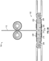
- FIG. 1 is a schematic depiction of an additive manufacturing system 100 using MHD printing of liquid metal 100 in which the disclosed improvements may be employed.
- Additive manufacturing system 100 can include a nozzle 102, a feeder system 104, and a robotic system 106.
- the robotic system 106 can move the nozzle 102 along a controlled pattern within a working volume 108 of a build chamber 110 as the feeder system 104 moves a solid metal 112 from a metal supply 113 and into the nozzle 102.
- the solid metal 112 can be melted via heater 122 in or adjacent to the nozzle 102 to form a liquid metal 112' and, through a combination of a magnetic field and an electric current acting on the liquid metal 112' in the nozzle 102, MHD forces can eject the liquid metal 112' from the nozzle 102 in a direction toward a build plate 114 disposed within the build chamber 110.
- an object 116 e.g., a two-dimensional object or a three-dimensional object
- the object may be formed based on a model 126 enacted through a controller 124.
- the object 116 can be moved under the nozzle 102 (e.g., as the nozzle 102 remains stationary).
- the liquid metal 112' can be ejected from the nozzle 102 in successive layers to form the object 116 through additive manufacturing.
- the feeder system 104 can continuously, or substantially continuously, provide build material to the nozzle 102 as the nozzle 102 ejects the liquid metal 112', which can facilitate the use of the three-dimensional printer 100 in a variety of manufacturing applications, including high volume manufacturing of metal parts.
- MHD forces can be controlled in the nozzle 102 to provide drop-on-demand delivery of the liquid metal 112' at rates ranging from about one liquid metal drop per hour to thousands of liquid metal drops per second and, in certain instances, to deliver a substantially continuous stream of the liquid metal 112'.
- a sensor or sensors 120 may monitor the printing process as discussed further below.
- the nozzle can include a housing 202, one or more magnets 204, and electrodes 206.
- the housing 202 can define at least a portion of a fluid chamber 208 having an inlet region 210 and a discharge region 212.
- the one or more magnets 204 can be supported on the housing 202 or otherwise in a fixed position relative to the housing 202 with a magnetic field "M" generated by the one or more magnets 204 directed through the housing 202.
- the magnetic field can be directed through the housing 202 in a direction intersecting the liquid metal 112' as the liquid metal 112' moves from the inlet region 210 to the discharge region 212.
- the electrodes 206 can be supported on the housing 202 to define at least a portion of a firing chamber 216 within the fluid chamber 208, between the inlet region 210 and the discharge region 212.
- the feeder system 104 can engage the solid metal 112 and, additionally or alternatively, can direct the solid metal 112 into the inlet region 210 of the fluid chamber 208 as the liquid metal 112' is ejected through the discharge orifice 218 through MHD forces generated using the one or more magnets 204 and the electrodes 206.
- a heater 226 may be employed to heat the housing 202 and the fluid chamber 208 to melt the solid metal 112.
- a discard tray 127 is located in proximity to the build plate and the nozzle may deposit droplets in it during a testing or calibration step.
- an electric power source 118 can be in electrical communication with the electrodes 206 and can be controlled to produce an electric current "I” flowing between the electrodes 206.
- the electric current "I” can intersect the magnetic field "M” in the liquid metal 112' in the firing chamber 216. It should be understood that the result of this intersection is an MHD force (also known as a Lorentz force) on the liquid metal 112' at the intersection of the magnetic field "M” and the electric current "I".
- the one or more magnets 204 and the electrodes 206 can be oriented relative to one another to exert the MHD force on the liquid metal 112' in a predictable direction, such as a direction that can move the liquid metal 112' toward the discharge region 212.
- the MHD force on the liquid metal 112' is of the type known as a body force, as it acts in a distributed manner on the liquid metal 112' wherever both the electric current "I” is flowing and the magnetic field "M” is present. The aggregation of this body force creates a pressure which can lead to ejection of the liquid metal 112'.
- the electrical power source 118 can be controlled to pulse the electric current "I" flowing between the electrodes 206.
- the pulsation can produce a corresponding pulsation in the MHD force applied to the liquid metal 112' in the firing chamber 216. If the impulse of the pulsation is sufficient, the pulsation of the MHD force on the liquid metal 112' in the firing chamber 208 can eject a corresponding droplet from the discharge region 212.
- the pulsed electric current "I” can be driven in a manner to control the shape of a droplet of the liquid metal 112' exiting the nozzle 102.
- a change in direction (polarity) of the electric current "I” across the firing chamber 216 can change the direction of the MHD force on the liquid metal 112' along an axis extending between the inlet region 210 and the discharge region 212.
- the electric current "I” can exert a pullback force on the liquid metal 112' in the fluid chamber 208.
- Each pulse can be shaped with a pre-charge that applies a small, pullback force (opposite the direction of ejection of the liquid metal 112' from the discharge region 212) before creating an ejection drive signal to propel one or more droplets of the liquid metal 112' from the nozzle 102.
- the liquid metal 112' can be drawn up slightly with respect to the discharge region 212.
- Drawing the liquid metal 112' slightly up toward the discharge orifice in this way can provide numerous advantageous, including providing a path in which a bolus of the liquid metal 112' can accelerate for cleaner separation from the discharge orifice as the bolus of the liquid metal is expelled from the discharge orifice, resulting in a droplet with a more well-behaved (e.g., stable) shape during travel.
- the retracting motion can effectively spring load a forward surface of the liquid metal 112' by drawing against surface tension of the liquid metal 112' along the discharge region 212.
- the forces of surface tension can help to accelerate the liquid metal 112' toward ejection from the discharge region 212.
- each pulse can be shaped to have a small pullback force following the end of the pulse.
- the pullback force is opposite a direction of travel of the liquid metal 112' being ejected from the discharge region 212, the small pullback force following the end of the pulse can facilitate clean separation of the liquid metal 112' along the discharge region 212 from an exiting droplet of the liquid metal 112'.
- the drive signal produced by the electrical power source 118 can include a wavelet with a pullback signal to pre-charge the liquid metal 112', an ejection signal to expel a droplet of the liquid metal, and a pullback signal to separate an exiting droplet of the liquid metal 112' from the liquid metal 112' along the discharge region 212. Additionally, or alternatively, the drive signal produced by the electrical power source 118 can include one or more dwells between portions of each pulse.
- liquid metal shall be understood to include metals and metal alloys in liquid form and, additionally or alternatively, includes any fluid containing metals and metal alloys in liquid form, unless otherwise specified or made clear by the context.
- Metals suitable for use with the disclosure include aluminum and aluminum alloys, copper and copper alloys, silver and silver alloys, gold and gold alloys, platinum and platinum alloys, iron and iron alloys, and nickel and nickel alloys.
- FIGs 3A-3D depict the formation of a droplet during the MHD printing process.
- a meniscus 301 can be seen wetted to a nozzle stem face 302.
- an MHD force 303 acts to increase the size of the meniscus 301 to form a droplet.
- the droplet 304 can be seen having separated from the meniscus.
- the droplet 304 can be seen in flight towards a build plate or object being manufactured.
- the characteristics of the rapidly moving droplets and/or stream are monitored. These characteristics may be compared against acceptable specifications, and operating parameters of the printer may be adjusted to keep the characteristics within specifications and/or compensate for those which are out of specification.
- the measurement, evaluation and adjustment process may be performed during a period of interruption in the printing process, such as during a cleaning and evaluation cycle.
- the nozzle and substrate may be temporarily positioned such that droplets do not land on the substrate but are instead directed to a waste area such as a discard tray.
- This setup has the advantage that jetting for building an object can be accomplished very close to the object (where optical observation of the droplets would be difficult), while jetting for evaluation can be made with larger distances.
- the measuring, evaluation and adjustment process may be performed continuously while printing is taking place.
- a strobed light source made using a pulsed LED or using other means known in the art is directed at the stream at an angle perpendicular (or nearly so) to the droplet trajectory.
- a camera having a sensor size and lens parameters, and user-controllable exposure start time and duration, is also directed at the stream at an angle perpendicular to the droplet trajectory.
- Figure 4 depicts a side view of a first schematic setup for monitoring droplets ejected during a maintenance period or during MHD printing.
- a nozzle 401 ejects a droplet 402.
- a camera 403 captures light from strobed light source 404 that is reflected off the droplet 402.
- An optional non-reflective surface 405 is positioned such that the droplet falls between the camera and the non-reflective surface 405.
- Figure 5 depicts a top view of a second schematic setup for MHD monitoring.
- a first camera 501 and a second camera 502 are set with their fields of view at right angles to one another. These cameras each capture light from strobed light source 503 that is reflected off the droplet 504.
- Optional non-reflective surfaces 505 are positioned such that the droplet 504 falls between the cameras and the non-reflective surfaces 505.
- FIG. 6 depicts a flow chart of an embodiment monitoring method.
- an ongoing MHD printing process is suspended.
- the nozzle is positioned over a discard tray and in a position where a stream of droplets can be observed by the monitoring system.
- droplets of liquid metal are jetted into the discard tray.
- the light source is strobed and light is reflected off of the droplets.
- images are captured by the camera or cameras of the monitoring system.
- those images are analyzed to determine the parameters of the jetting. Those parameters can be compared in step 607 to desired parameters. If corrective action is not needed, the process is ended. If corrective action is needed, that may then be performed in step 608.
- the printing parameters may also be adjusted, for instance the current or magnetic field strength and/or frequency may be adjusted.
- the process is returned to step 603 and another test print is performed. This process may be repeated until the printer is operating within acceptable parameters and then returned to service. The printer may also be withdrawn from service and the print canceled if the desired parameters are exceeded by a sufficient degree or corrective action repeatedly fails to return the printing parameters to acceptable conditions.
- the shutter duration of the camera, the duration, frequency, and number of the strobe light flashes, as well as the timing of both shutter and strobe flashes relative to the time a droplet is ejected, are manipulated such that an individual droplet is illuminated several times while in the camera's field of view and while the camera is acquiring an image.
- liquid metal drops are substantially spherical and highly reflective, only a small number of the light rays reflected from the drop will enter the camera lens, but the intensity of these rays will be high compared to a less reflective material. As a result, a relatively bright, sharp point will appear in the camera image, tending to show the geometric center of the single drop at the time each strobe flash occurred. This makes subsequent analysis of the drop position easier.
- the region of the stream viewed by the camera is that region between the nozzle and the substrate during printing, and the strobe flashes occur quickly enough that the drop is illuminated several times during its flight from nozzle to substrate. In this way, the stream can be continuously monitored during printing.
- the image described above is analyzed to determine the size and position of the artifacts described above.
- the artifacts are small points of white on an otherwise dark background, and a computer program such as OpenCV (Open Source Computer Vision Library) is used to find the position of these points.
- OpenCV Open Source Computer Vision Library
- the drop stream is backlighted by the strobe using a diffuser, and the resulting image shows dark silhouettes of the drops at each strobe flash against a light background, reflecting the drop's size, shape, and position at each time the strobe fired.
- the distance between the artifacts in the image is proportional to the drop speed, and the absolute speed of a drop may be calculated with useful accuracy given proper calibration of the camera, lens, and strobe frequency.
- the camera and lens combination is set to a fixed focus, and a precision distance scale is erected at the distance yielding the clearest image. An image of the scale is captured, and a conversion between camera pixels and distance thereby obtained. During jetting, the distance between drops can be accurately measured so long as the drops fall in the same plane previously occupied by the scale.
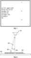
- Figure 7 depicts a camera image showing several drop reflection artifacts of the same drop.
- the distance between artifacts (compensating for optics) was 0.63 mm, and the strobe frequency was 4000 Hz or 0.00025s between flashes. Dividing the distance by the time yields a drop velocity of 2.52 m/s.
- the image is overlaid with numbers next to each artifact recognized by the computer-vision software, as well as statistics in the following order: speed of the current drop, angle of the current drop, and the following statistics for the prior 25 drops: exponentially-weighted moving average speed, standard deviation of speed, average change in drop-to-drop speed, difference between highest and lowest speed, average angle.
- the last statistic is the number of consecutive frames with no drops found (indicating possible nozzle failure), in this case zero. ⁇ OK' indicates that the recognition of drop artifacts passes several internal checks.
- Fig. 8 depicts undesirable characteristics during MHD printing.
- Nozzle 801 deposits droplets 802 to form an object 803 on a build plate 804.
- An artifact 805 can be seen in proximity to a droplet. It can be seen that the jetting path of the droplets is off of the intended ejection path by an angle 806.
- a camera provides 752 pixels in the longer dimension of its frame, each pixel measuring 6 um in size, for an image length of 4.51 mm.
- the desired field of view is chosen to be 3 mm, which is the standoff distance between the nozzle outlet and substrate during printing. The ratio of these quantities is the desired magnification of 1.5x.
- the maximum discretization error due to pixel size is 3 um at the image or approximately 2 um at the droplets.
- a lens of 25 mm focal length is chosen, and standard lens equations are used to calculate the working distance: 41.67 mm.
- the nominal drop size is 250 um, so 12 droplets would fit end-to-end in a 3 mm field of view.
- the strobe frequency is divided by two so that a one-diameter gap is left between each droplet artifact in the image. (Note that due to the effect described above, the reflected light artifact may be smaller than the actual droplet, so the gap may not be needed depending on lens quality.) With a maximum droplet speed of 2 m/s, and a desired pitch of 500um, the strobe flashes should occur at 4000 Hz to provide the desired spacing.
- the distance between subsequent jetted drops will be larger than the camera field of view.
- the strobe frequency is manipulated such that the artifacts appear in "groups", each group consisting of artifacts from a specific drop. For example, with a jetting frequency of 500 Hz and a speed of 1 m/s, the distance between drop centers will be 2mm.
- either one or two drops will be visible in the camera at any time.
- a strobe frequency of 2000Hz the distance between artifacts will be .5mm.
- the apparent gap between the last artifact of one drop and the first artifact of the next drop will be larger than the gap between artifacts of the same drop.
- the computer-vision software can be programmed to recognize these gaps to distinguish between drops and calculate individual velocities.
- the drops themselves are used in lieu of multiple flashes of the strobe light.
- the strobe light may be flashed at an arbitrary frequency and multiple drop artifacts will always appear in the image. Assuming the jetting frequency is known, the positions of these artifacts can be used to calculate the velocity of at least some of the drops. Further, variations in the distance between drop artifacts can be used to determine variations in drop speed between subsequent drops. If the frequency chosen is the jetting frequency or a factor of it, the drops will tend to appear in the same location in every image, possibly aiding analysis.
- each strobe flash is also calculated. The longer the strobe flash and the faster the droplet speed, the more "smeared" each reflected artifact will appear. Depending on the software algorithm used to locate the reflections in the image, this could reduce quality. Assuming a maximum allowed blur of 5% of drop diameter, the drop at 2 m/s will move 12.5um in 6.25 us. It will be understood that shorter pulses provide less smearing effect, while longer ones provide more light for the camera's exposure. In this calculation, a burst of six strobe flashes, each 6 us in duration, occurring at 4000 Hz, will illuminate the drop six times over a 3 mm distance at top speed. The exposure time of the camera would need to be greater than 1.25 ms to capture all six flashes, but less than the time for the next droplet to arrive (which depends on jetting frequency) to avoid capturing reflections from multiple droplets.
- the camera and strobe are triggered together just after a drop is jetted, such that the drop is captured two or more times while within the camera's field of view, resulting in the multiple exposure described above.
- the resulting image is converted to one-bit (black and white) using a threshold determined experimentally. Due to the sharpness and contrast of the image, a wide range of thresholds will be effective.
- a Hough Circle Transform or similar function is used to identify the X,Y location in the image of the points representing the drop.
- the X,Y data, in camera pixels is then multiplied by the factor determined during calibration. At this point the data can be analyzed in a number of ways, some of which are described below.
- the velocity of the jetted drop is calculated as follows: The points found are sorted along the direction of jetting. Next, the distance between each point and its immediate neighbor is calculated using the Pythagorean theorem and recorded. This yields n-1 distances for n points. The mean and standard deviation (SD) of the distances is calculated, with the standard deviation giving a measure of data quality since any errant drops or other image anomalies will often produce large outliers. Assuming the SD is reasonable, the mean distance is divided by the time between strobe flashes to yield a velocity. In one embodiment, the calculated means of a plurality of captured images are themselves averaged, yielding a low-pass-filtered average drop speed.
- the change in drop speed per unit time can indicate resonance of the nozzle or liquid metal.
- movement of the drop images within the frame without a corresponding speed change can indicate a change in drop formation time after the jetting pulse, which can indicate a change in internal nozzle condition (such as air ingestion, dewetting, or cracking).
- a line is fitted to the X,Y points in the image using the least-squares method, and the angle of this line calculated as the arctangent of the distance traveled normal to the intended jetting direction, divided by the distance traveled along it.
- the camera mounting is calibrated to a known angle (for example the surface of the substrate to be printed on), a deviation from that desired angle can be calculated, otherwise a plurality of images can be analyzed to observe changes in jetting angle over time, which can indicate an issue with the nozzle.
- two cameras observe the stream from different directions, allowing any stream angle to be observed.
- the directions are at right angles from each other, which allows maximum accuracy of measurement, as shown in Figure 2 . Note that the cameras do not need to be aligned with the axes of motion of the printer system.
- rapid changes in the measured angle between frames can indicate oscillation or jitter which could result in incorrect droplet placement on the substrate.
- drop and stream characteristics can likewise be inferred and/or calculated by additional analysis of the image. For example, should a drop fail to be ejected, this will be seen as an "empty" image. Depending on the frequency of this condition, the control system of a printer might initiate a nozzle cleaning, or gauge remaining nozzle life. In certain embodiments, an infrared camera may be employed, however generally images will capture an image having a blurred line representing the stream of droplets unless a very short shutter speed is employed.
- unwanted "satellites” or secondary drops are detected as follows. Again the drops are sorted along the direction of jetting, but in this case the angle between each drop and its immediate neighbor is calculated. Should these angles deviate from each other by more than a small amount, this indicates multiple streams are present.
- satellites are detected by the presence of multiple drops at the same distance along the jetting direction, drops at extreme angles, or very large differences between velocities between drops.
- points are grouped by their calculated velocity, then line fits are done within the groups.
- the amount of motive force on the liquid is adjusted to keep droplet speed within the desired range.
- the motive power can be adjusted by increasing the current, increasing the duration of a pulse creating a drop, or a combination of these.
- excessive deviation of the stream angle from specification triggers an automatic cleaning of the jetting nozzle.
- a print job is aborted altogether if parameters deviate too far from specification.
- the commanded position of the substrate during printing is adjusted to compensate for changes in droplet speed and trajectory, causing the drops to land closer to the desired location on the substrate than they would without such compensation.
- the drops are backlit as described above. Unlike the direct lighting described previously, the backlit illumination provides a silhouetted image of the falling drop, and thus the resulting image may reflect both the shape and size of the droplet at the moment the strobe fires. This effect could be used to estimate drop size, and to track droplet vibration during flight.
- the strobe frequency of the strobe is varied to reduce or eliminate aliasing in the images caused by drop vibration in flight.
- drops may not be perfectly spherical but may oscillate between various oblong shapes. The altered shape can change the apparent location of the reflected artifact.
- a strobe frequency to be a multiple of this oscillation frequency, the drop will appear in the same orientation in each artifact, yielding consistent placement.
- the analyses described can be done several times per second even on modest computer hardware. Thus at low frequencies, every drop might be captured. However, at higher frequencies, a system might only capture a portion of the drops jetted. In order to prevent overlooking certain variations (especially resonance), the jetting velocity and/or capture frequency can be varied in an attempt to change the aliasing that might occur at a single frequency.
- One goal of the present disclosure is to detect deviation in stream angle from the desired one both instantaneously and over time. If this deviation is normal to the camera's viewing axis, or has a substantial component in that direction, the deviation is easily registered by the camera. However, if the deviation is toward or away from the camera, a lens with sufficient depth of field will continue to see the same angle, with slightly reduced velocity.
- a lens with intentionally limited depth of field for example, with no iris or the iris fully open
- a second camera and lens assembly observes the illuminated stream from a direction at right angles to the that of the first camera.
- the second camera need not measure velocity.
- it could be equipped with a lens of lower magnification, providing a larger field of view useful for detecting secondary streams or satellites, or for scanning the part surface.
- a camera of lesser specification could be employed, reducing the cost of the system.
- its detection algorithm could be limited to angle only, reducing computational requirements.
- the camera and strobe light source can be connected to prisms, mirrors, light pipes, or other optics which allow them to be mounted in a convenient location.
- a single strobe/camera set can observe multiple streams, and the analysis algorithm can calculate statistics for them separately.
- the portion of the part already printed will appear in the frame, requiring more complex computer-vision algorithms to ignore it.
- Another issue is that depending on the area of the part being printed, the portion already printed may extend toward the camera by up to many inches, possibly creating a blurring of the image in this area and obscuring the drop artifacts.
- the cameras are aimed slightly downward so that the drops are always visible regardless of the part position.
- a lens with very narrow depth of field for example 0.5-2mm
- the computer-vision software is programmed to ignore the portion of the image comprising the part geometry.
- the light from the strobe is polarized to prevent unwanted low-angle reflections from the part.
- the printer control will need to move the part and head away from each other.
- the camera is at a fixed height relative to the part, and is chosen to have a wide field of view in the direction of build, so that the drops can be seen over many layers.
- the camera is moved or tilted in concert with the movement of the head to keep the droplets in the same place in the image frame.
- the head and camera are stationary, and the part is moved down to accommodate additional layers.
- MHD jetting Maintenance of constant conditions at the nozzle exit is a particular concern in the context of MHD jetting, where a number of factors combine to increase the likelihood angle of molten metal wetting to nozzle materials, even when materials that are typically considered non-wetting, such as alumina ceramic, are used.
- MHD printing can operate at a wide range of frequencies, but typically ranging between tens of hertz and single kilohertz. This jetting produces vibration throughout the nozzle assembly, which can break up oxide skins, improve metal-substrate contact and generally promote wetting.
- the process of forcing molten metal through a small-diameter tube - as is done when metal is forced out of the nozzle in MHD printing - can further help remove oxide from molten metal, improving the metal's wetting properties. Consequently, it is of great value in MHD printing to employ nozzle geometries and constructions that enable a consistent meniscus of molten metal to be developed and maintained.
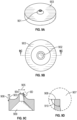
- the discharge orifice is located within a small boss, here referred to as the nozzle stem.
- Figs. 9A-9D depict a nozzle geometry having a stem 901. It should be understand that the nozzle stem 901 is shown and described as being in an upper region of the nozzle and the body of the nozzle is described as being a bottom feature, but that in operation the nozzle stem will be positioned facing downward to jet liquid metal onto a build plate. Stem face 902 is displaced along the axis of the jet by some distance 903 away from the bottom of the nozzle body, referred to here as the nozzle bottom 902. In a preferred embodiment, this distance 903 may be between 150 ⁇ m and 350 ⁇ m, although other distances may be desirable in other preferred embodiments.
- the produced meniscus of molten metal can be largely constrained by the face of this boss, providing an outer limit to the geometry that the meniscus adopts.
- the outer edge 907 of the boss acts to 'pin' the meniscus by providing a location where the meniscus can take a wide range of angles with respect to the face of the boss without moving appreciably. This may be understood by noting that microscopically, the edge, while appearing infinitely sharp in drawings, actually has a finite (but very small) radius. For this reason, the meniscus can assume a range of angles by moving along the surface of this small radius.
- the offset 903 between the stem face and the nozzle body can provide decoupling between the meniscus on the stem face and other molten metal around the nozzle stem, for instance in the situation where the nozzle has "wetted over" (see below for description).
- the nozzle stem may be designed to produce a specific nozzle inner diameter 904, outer diameter 905, combination of inner and outer diameters, or fixed relationships between inner and outer diameters. It has been observed that the interaction between these two parameters defines the diameter of the drop that is produced by the jetting process. Generally, drop diameter is at a minimum when the meniscus has not developed across the face of the nozzle. As wetting progresses and the meniscus expands across the face of the stem, the drop diameter will increase. However, the effect of increasing meniscus diameter on drop sizes may not be linear, and the incremental change in effect size will decrease as the meniscus size grows.
- Concentricity between the inner diameter 904 of the nozzle - the nozzle exit - and the outer diameter 905 of the nozzle stem may also be preferable to control. These diameters are identified in Figure 9C .
- the lateral force applied to a drop exiting the nozzle by the meniscus increases with meniscus width, and an asymmetric meniscus will apply an asymmetric force to the ejected drop, producing an angle in the drop stream.
- concentricity better than 5% of the nozzle inner diameter has been found to be adequate. In one preferred embodiment, for nozzles with a 360 ⁇ m outer diameter and a 254 ⁇ m inner diameter, concentricity better than 12 ⁇ m was found to be acceptable in the formation of droplets during jetting.
- the surface quality of the stem face is important to control because surface roughness is known to affect wetting. Different combinations of jetted material and nozzle material may have different optimal surface conditions to produce specific wetting characteristics. Similarly, the quality of the inner edge 908 and outer edge 907 of the stem face 902 may be preferable to control, to ensure that flow from the nozzle throat into the meniscus is symmetric, and that the outer edge of the meniscus is symmetric when it is fully developed.
- the nozzle has an internal cavity 909 in which liquid metal is contained for jetting.
- a surface roughness of 0.05 ⁇ m R a or better, and 0.3 ⁇ m R max or better is produced by polishing a stem face with an appropriate series of abrasives. For example, for a ceramic nozzle, diamond abrasives down to 3 ⁇ m may be used to provide this finish. During the polishing process, sufficient material is removed to eliminate all pits in the stem face, or chips in the inner and outer edges of the stem face, larger than some multiple of the surface roughness. For example, the stem face may be polished until all pits or chips larger than 3 times the R max surface roughness have been removed. In this manner, a defined surface roughness and edge quality may be produced.
- the process described above may be employed, followed by subsequent polishing with a coarser abrasive to produce a rougher surface finish on the stem face while maintaining the edge quality desired.
- the initial polishing process may be followed by a second polishing process using a 10 ⁇ m diamond abrasive.
- Other parameters, such as lay pattern, may also be specified using the polishing methods described above.
- the specific surface roughness achieved may be changed to provide different effects. For example, a given material may demonstrate different wetting behaviors for different surface roughness levels; or one material may provide a desired wetting behavior at one surface roughness level, while a different material provides a desired wetting behavior at a higher or lower surface roughness level.
- the angle 910 between the stem face and the sides of the stem can be varied to provide different effects.
- a steeper angle provides more resistance to a phenomenon called "wetting over,” where the molten metal meniscus spreads beyond the boundary of the stem face and travels down over the side of the stem.
- This phenomenon may be caused by a variety of mechanisms, including satellite drops generated during jetting flying backwards and splattering on the nozzle bottom, where they build up and wet to the nozzle; or an asymmetric jet angle that produces asymmetric splash-back against the nozzle face, which eventually forces molten metal over the side of the stem.
- a shallower angle conversely, may be easier to manufacture, as it may result in a thicker, stronger stem, and may reduce the chance of edge chipping during manufacturing.
- the height of the stem is related to, but does not entirely define, the length of the tube leading from the nozzle interior cavity to the nozzle exit (here referred to as the nozzle throat).
- Throat length 907 is shown in Figure 9C .
- the length of this throat may affect the nozzle's jetting dynamics by increasing the fluid inertance in the nozzle. While throat length can also be modified by adjusting the position of the inner cavity relative to the bottom of the nozzle, in cases where the inner cavity's position must be fixed (for instance, to ensure adequate thermal flow from external heat sources into the inner cavity), the length of the nozzle stem may be adjusted instead. In certain embodiments, this throat length is between 250 ⁇ m and 400 ⁇ m, although other lengths may be desirable in other preferred embodiments.
- the axial displacement 903 between the stem face and the nozzle bottom may also help decouple the meniscus on the stem face from other molten metal in a "wetting over" event. Even if substantial molten metal builds up around the nozzle stem as shown in Figure 10A , the axial separation 903 may ensure that the outer perimeter of the stem face still defines the meniscus 1001 that acts on the droplet during a jetting event, which may help keep jetting efficiency high. This is particularly preferable in the case of stems where the angle between the stem face and sides is less than 90 degrees, for example as shown in Fig. 13D .
- Figure 10B depicts an over-wetted state in which the wetted region 1002 extends beyond the nozzle stem face.
- Axial displacement of the stem face can be taken advantage of in different preferred embodiments.
- one method of preventing nozzle "wetting over" while using nozzle materials that wet readily is to provide a shield of material around the stem, as shown in Figures 11A-C .
- a non-wetting material 1101 is bonded to the vicinity of the nozzle stem via bonding material 1102.
- this material could be boron nitride, or Macor (a machinable ceramic manufactured by Corning, Inc. of Corning, NY); other shield materials may be preferable, depending on the nozzle material and the molten metal in use.
- a paint is used to apply a conformal non-wetting shield around the stem.
- the paint contains some portion of a strongly non-wetting material. It also is preferably resistant to temperatures encountered at the nozzle tip.
- a boron nitride paint such as BN-Lubricoat TM manufactured by ZYP Coatings (Oak Ridge, TN) may be used.
- the paint may be applied to the nozzle bottom, and then pushed inwards towards the stem, such that it flows up the sides of the stem but does not flow over the edge on to the stem face. This process may be performed manually, or by an automated system. In this manner, a conformal non-wetting shield may be applied to the stem through use of paint, without applying the non-wetting coating to the stem face.
- a conformal shield of a different material is applied around the stem.
- This coating may absorb molten material and wick it away, in the manner of a sponge.
- the coating may be applied using the process described previously, or other processes may be used, such as dipping the stem in a bath of the material, allowing it to dry and then grinding material away to reveal the stem face.
- a vapor deposition process is used instead of painting to apply a strongly non-wetting coating around the stem.
- a perforation with the shape of the nozzle stem is formed in a sheet of shield material.
- the shield material is preferably softer than the nozzle material, so that the nozzle can be used to lap a hole into the shield material.
- the shield material may be boron nitride, pyrolytic boron nitride, or Macor.
- the shield material is then bonded to the nozzle bottom.
- the assembly is then finish-machined, by processes such as grinding, polishing or lapping, to ensure that the stem face and the top of the shield material are coplanar.
- the stem face and the shield material are recessed below the level of the shield as shown in Figure 11B or allowed to protrude above the level of the shield as shown in Figure 11C . Molten metal will wet to the stem face, but may be prevented from building up around the stem and/or substantially "wetting over" the stem by the shield plate.
- a double-stem nozzle design shown in Figure 12 , may be used.
- a first stem 1201 with a smaller diameter is fabricated on top of a second stem 1202 with a larger diameter.
- the axial displacement 1203 between this smaller stem face and the larger stem face is preferably smaller than the axial displacement 1204 between the larger stem face and the nozzle bottom.
- the axial displacement 1203 is selected to provide the desired jet stability improvements, while minimizing coupling between the meniscus 1205 on the smaller stem face during drop formation and the meniscus on the larger face, avoiding degradation of jetting efficiency.
- the nozzle is induced to "wet over" the small stem face and down to the large stem face, where a concentric, even wetted area may be developed.
- the outer contour of the small stem face may still be visible, as the meniscus developed on the large stem face may not completely obscure the small stem face, but instead develop over the large stem face and up to the outer contour of the small stem face.
- the angle of the meniscus at the outer contour of the smaller stem face may be decreased substantially.
- the larger axial displacement D between the large stem face and the nozzle bottom discourages further "wetting over” from the larger stem face.
- This nozzle may also be more readily manufacturable, thanks to the greater thickness of the stem contributed by the lower section.
- Lapping processes may be employed to modify the outer contours of the nozzle stem to provide this reduction.
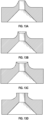
- a 60-degree chamfer tool may be used to lap the nozzle stem to a razor edge, as shown in Figure 13A .
- the lapping process may enable extremely fine features to be produced using this method.
- a stem may be manufactured with an internal chamfer to reduce the effective stem face area, as shown in Figure 13B .
- a stem may be manufactured with a concave depression of a dish radius manufactured into the stem face, as shown in Figure 13C .
- This depression may prevent material from splashing out and wetting over the side during the "splash-back" phase of jetting.
- This design also increases the effective angle between the stem face and the stem sides, further preventing "wetting over”.
- a stem may be manufactured with an undercut beneath the outer edge of the stem face, as shown in Figure 13D . This increases the effective angle between the stem face and the stem sides, further preventing "wetting over”.
- stems are manufactured integrally with nozzles.
- stems are manufactured as part of a separate element which is then attached to the nozzle.
- a stem may be manufactured in a flat shield of ceramic material, which is subsequently joined to the exterior a ceramic nozzle, using a joining process such as diffusion bonding.
- a stem may be manufactured in a tubular plug of ceramic, which is then mounted internally in a ceramic nozzle, using a joining process such as co-firing or ceramic epoxy to bond them.
- stems on these nozzle tips may be produced by green machining, bisque machining, grinding, injection molding, laser ablation machining or other techniques.
- the nozzle bottle or the entire nozzle including the nozzle body and nozzle stem may be constructed via injection molding.
- a nozzle may be removed during the printing process, either based on the monitoring of the print as it is underway or during scheduled intervals. This process may include positioning the nozzle in a designated cleaning area, such as over a discard tray where material may be deposited without interference with the object being printed. Nozzle maintenance may also be conducted before or after a print job is performed.
- dross which is solid or semi-solid materials containing oxides and in some instances additional contaminants, while preserving and maintaining the desired wetting of nozzle surfaces by the liquid metal.
- dross will include primarily aluminum, silicon, and magnesium oxides.
- a ceramic cloth or metal wire mesh 1501 may be employed, either in a loop or as a continuous sheet, to wipe dross 1502 away from a nozzle surface 1503.
- the cloth might be heated to keep the contaminants and metal molten. In other certain embodiments, this heating might be accomplished by passing electrical current though the cloth itself. In another embodiment, the cloth rides on a heated stationary "shoe" which heats the cloth and presses it against the nozzle.
- radial brushes 1504 or flat brushes 1505 to scrape dross 1502 off the nozzle surface 1503.
- the brushes are made of materials such as tantalum which resist the high temperature and reactivity of molten aluminum.
- a ceramic rod sized similar to or slightly larger than the nozzle hole is gently pressed against the nozzle face and rotated (See Figure 17A-B ).
- the diameter of the rod is chosen to be large enough to effectively remove the dross from the desired area, without being any larger, since diameter increase will increase heat conduction through the rod.
- the rod is approximately two to three times that of the nozzle orifice.
- the nozzle has a raised stem with an orifice through it, and the rod diameter is chosen to be 50% larger than outer diameter of the stem as illustrated in the figure.
- the ceramic may be chosen from a wide array of materials including alumina, mullite, silicon nitride, aluminum nitride, zirconia and silicon carbide. It is preferable that the thermal conductivity of the ceramic be relatively low so that, when contacting the liquid metal in the nozzle, the body of the rod does not remove excessive heat from the nozzle and the tip of the ceramic rod comes up to temperature rapidly. The rod is kept to a small diameter so as to further minimize the heat removed from the nozzle. As the rod is initially much colder than the heated nozzle, any liquid material on the nozzle face immediately freezes. However, since the rod is now in intimate contact with the hot nozzle, and has low thermal conduction along its length, the rod's end temperature rises.
- the ceramic rod is preheated to a temperature at or near the liquidus of the metal being jetted. This eliminates the freeze/thaw step described above, and allows cleaning to occur more quickly. The process of radial extrusion from the gap remains the same as described in the previous paragraph.
- the rod is domed or pointed, this shape assists in the urging outward of dross away from the center of the nozzle and wiping the exit of the nozzle orifice as the rod turns.
- An additional benefit is that the dome or point self-centers on the nozzle bore, reducing the precision required to place the cleaning rod.
- the gentle force described above is applied by spring-loading the rod or its mounting, and moving the nozzle down onto the rod a known amount after contact is made, producing a known force.
- a constant-force spring or mechanism is used, producing a known force regardless of movement after contact.
- the mounting of the rod is designed with inherent compliance, which behaves as a spring.
- an air cylinder is used to apply force in proportion to the gas pressure applied to the port of the cylinder.
- Additional techniques can be used to modify or maintain the wetting. Relatively heavy force applied to the spinning rod tends to dewet the nozzle, while lighter force and/or the addition of additional molten metal to the tip of the rod tends to wet the nozzle face. In the case of a larger amount of material, a short burst of high-pressure gas alone can dislodge the material.
- Fig. 16 depicts a flow chart for an embodiment cleaning technique as performed during a jetting process.
- ongoing jetting is suspended, and the nozzle is placed over a ceramic rod above a discard tray.
- a bead of metal is jetted onto a top surface of the ceramic rodi .
- the ceramic rod is rotated and the bead pressed against the nozzle face.
- the rotating bead of metal is at least partially liquid and in contact with the meniscus of liquid metal and dross is picked up. This process may be accomplished with the rod close to the nozzle, for example within the order of hundreds of microns, but without contact, which prevents wear on the nozzle.
- Additional liquid metal may continue to be jetted onto the existing bead, which will eventually increase in size until it is ejected off the top surface of the ceramic rod.
- the bead may be physically knocked off of the ceramic rod. Jetting may be continued to maintain wetting of the nozzle.
- the jetting and/or meniscus conditions of the nozzle may be evaluated to determine if additional cleaning or conditioning is required. If so, such maintenance can be conducted or otherwise the nozzle can be returned to operation.
- Fig. 17A-B depict the cleaning process of Fig. 16 .
- ceramic rod 1701 is moved in vicinity of nozzle 1702, having a meniscus 1703 with an amount of dross 1704.
- a bead of metal 1705 is jetted onto a top surface 1706 of the ceramic rod 1701.
- the ceramic rod presses the bead of metal 1705 against the nozzle 1702.
- a large bead of metal may be collected on the tip of the nozzle and allowed to freeze the meniscus to the ceramic rod.
- the rod may then be withdrawn or a fast-moving object may be used to knock the bead off of the nozzle.
- the ceramic rod may freeze the meniscus to it when it comes in contact with the meniscus, which may de-wet the nozzle. Heating of the ceramic rod or the environment may be employed to prevent this or the solidification of a bead being used to clean the nozzle.
- the ceramic rod when a bead of metal on a ceramic rod is being employed to clean the stem of the nozzle, the ceramic rod may be moved laterally relative to the stem face in a predetermined pattern.
- Figure 18 depicts a top plan view of a particular pattern that may be employed, in which the ceramic rod is oscillated back and forth in a first direction while being moved laterally in a second direction. Alternatively, other patterns such as spiral may be employed.
- a nozzle stem may be rewetted.
- a ball of material 1901 approximately 3-5 nozzle diameters in size is jetted onto the rotating tip of rod 1902 and then the tip is slowly moved up onto the hot nozzle 1903, flattening the drop onto the nozzle, leaving a wetting meniscus 1904.
Landscapes
- Engineering & Computer Science (AREA)
- Chemical & Material Sciences (AREA)
- Materials Engineering (AREA)
- Manufacturing & Machinery (AREA)
- Mechanical Engineering (AREA)
- Automation & Control Theory (AREA)
- Analytical Chemistry (AREA)
- Physics & Mathematics (AREA)
- Optics & Photonics (AREA)
- Dispersion Chemistry (AREA)
- Signal Processing (AREA)
- Health & Medical Sciences (AREA)
- Life Sciences & Earth Sciences (AREA)
- Biochemistry (AREA)
- General Health & Medical Sciences (AREA)
- General Physics & Mathematics (AREA)
- Immunology (AREA)
- Pathology (AREA)
- Ink Jet (AREA)
- Particle Formation And Scattering Control In Inkjet Printers (AREA)
- Investigating Materials By The Use Of Optical Means Adapted For Particular Applications (AREA)
- Chemical Treatment Of Metals (AREA)
Applications Claiming Priority (9)
| Application Number | Priority Date | Filing Date | Title |
|---|---|---|---|
| US201862733980P | 2018-09-20 | 2018-09-20 | |
| US201862734025P | 2018-09-20 | 2018-09-20 | |
| US201862734015P | 2018-09-20 | 2018-09-20 | |
| US201962823171P | 2019-03-25 | 2019-03-25 | |
| US201962823757P | 2019-03-26 | 2019-03-26 | |
| US201962823748P | 2019-03-26 | 2019-03-26 | |
| US201962830744P | 2019-04-08 | 2019-04-08 | |
| EP19863811.6A EP3852956B1 (fr) | 2018-09-20 | 2019-09-20 | Techniques d'amélioration de performance d'éjection de mhd |
| PCT/US2019/052297 WO2020061544A1 (fr) | 2018-09-20 | 2019-09-20 | Techniques d'amélioration de performance d'éjection de mhd |
Related Parent Applications (1)
| Application Number | Title | Priority Date | Filing Date |
|---|---|---|---|
| EP19863811.6A Division EP3852956B1 (fr) | 2018-09-20 | 2019-09-20 | Techniques d'amélioration de performance d'éjection de mhd |
Publications (2)
| Publication Number | Publication Date |
|---|---|
| EP4491290A2 true EP4491290A2 (fr) | 2025-01-15 |
| EP4491290A3 EP4491290A3 (fr) | 2025-04-23 |
Family
ID=69887941
Family Applications (2)
| Application Number | Title | Priority Date | Filing Date |
|---|---|---|---|
| EP19863811.6A Active EP3852956B1 (fr) | 2018-09-20 | 2019-09-20 | Techniques d'amélioration de performance d'éjection de mhd |
| EP24215165.2A Withdrawn EP4491290A3 (fr) | 2018-09-20 | 2019-09-20 | Techniques pour améliorer les performances d'éjection de mhd |
Family Applications Before (1)
| Application Number | Title | Priority Date | Filing Date |
|---|---|---|---|
| EP19863811.6A Active EP3852956B1 (fr) | 2018-09-20 | 2019-09-20 | Techniques d'amélioration de performance d'éjection de mhd |
Country Status (3)
| Country | Link |
|---|---|
| US (1) | US20210379664A1 (fr) |
| EP (2) | EP3852956B1 (fr) |
| WO (1) | WO2020061544A1 (fr) |
Families Citing this family (32)
| Publication number | Priority date | Publication date | Assignee | Title |
|---|---|---|---|---|
| US11420391B2 (en) * | 2018-05-17 | 2022-08-23 | Diabase Prototyping And Engineering Llc | Cleaning mechanism for 3D printer |
| US12083599B2 (en) * | 2019-04-12 | 2024-09-10 | Additive Technologies Llc | Nozzle cleaning in jetting of metal alloys |
| JP7505177B2 (ja) * | 2019-11-25 | 2024-06-25 | 株式会社リコー | 液吐出ヘッド及びその製造方法、液吐出装置、並びに液吐出方法 |
| US12415229B2 (en) | 2020-07-29 | 2025-09-16 | Blue Origin Manufacturing, LLC | Friction stir welding systems and methods |
| US11261076B1 (en) * | 2020-08-13 | 2022-03-01 | Pepsico, Inc. | Beverage dispense monitoring with camera |
| CN112024887B (zh) * | 2020-08-25 | 2021-07-20 | 苏州复浩三维科技有限公司 | 一种优化陶瓷隔离层打印的方法和系统 |
| CA3191397A1 (fr) | 2020-09-03 | 2022-03-10 | Peter Schmitt | Systeme ameliore de depot de metal |
| JP7593138B2 (ja) * | 2021-01-26 | 2024-12-03 | セイコーエプソン株式会社 | 三次元造形装置および三次元造形物の製造方法 |
| US20220258240A1 (en) * | 2021-02-12 | 2022-08-18 | Desktop Metal, Inc. | The jetting performance of molten metal alloys by controlling the concentration of key alloying elements |
| US20220266513A1 (en) * | 2021-02-25 | 2022-08-25 | Palo Alto Research Center Incorporated | Drop-on-demand printer having optimized nozzle design |
| US11760000B2 (en) * | 2021-05-07 | 2023-09-19 | Xerox Corporation | Characterizing meniscus behavior in 3D liquid metal printing |
| US11724441B2 (en) * | 2021-05-07 | 2023-08-15 | Palo Alto Research Center Incorporated | Characterizing meniscus behavior in 3D liquid metal printing |
| US11808680B2 (en) * | 2021-05-27 | 2023-11-07 | Xerox Corporation | System and method for characterizing liquid metal drops jetted from a 3D printer using a strobe light |
| US11945169B2 (en) * | 2021-05-27 | 2024-04-02 | Xerox Corporation | System and method for characterizing liquid metal drops jetted from a 3D printer using a strobe light |
| US12002265B2 (en) * | 2021-06-24 | 2024-06-04 | Xerox Corporation | Characterizing liquid reflective surfaces in 3D liquid metal printing |
| US11958112B2 (en) | 2021-06-24 | 2024-04-16 | Xerox Corporation | Characterizing liquid reflective surfaces in 3D liquid metal printing |
| DE102021117285A1 (de) | 2021-07-05 | 2023-01-05 | Grob-Werke Gmbh & Co. Kg | Vorrichtung zur additiven fertigung eines bauteils |
| US11839916B2 (en) * | 2022-01-20 | 2023-12-12 | Additive Technologies Llc | Device and method for cleaning an orifice in a metal drop ejecting three-dimensional (3D) metal object |
| US20230339024A1 (en) * | 2022-04-21 | 2023-10-26 | Palo Alto Research Center Incorporated | Optical systems for drop-on-demand three-dimensional (3d) object printing |
| US12198323B2 (en) * | 2022-06-15 | 2025-01-14 | Xerox Corporation | Image processing techniques for jetting quality classification in additive manufacturing |
| EP4601824A1 (fr) * | 2022-10-11 | 2025-08-20 | Desktop Metal, Inc. | Traitement au plasma de surfaces projetées pour créer des supports cassables en impression magnétohydrodynamique d'aluminium |
| US12121971B2 (en) | 2022-11-09 | 2024-10-22 | Xerox Corporation | Real-time molten droplet analyzer with spatial modulation in additive manufacturing |
| US12454004B2 (en) | 2022-11-09 | 2025-10-28 | Xerox Corporation | Real-time molten droplet analyzer with spatial modulation in additive manufacturing |
| US20240149355A1 (en) * | 2022-11-09 | 2024-05-09 | Palo Alto Research Center Incorporated | Real-time liquid metal droplet analyzer with spatial modulation in additive manufacturing |
| US12208616B2 (en) | 2022-11-29 | 2025-01-28 | Additive Technologies, LLC | Inspection system for three-dimensional printer and methods thereof |
| US12246392B2 (en) | 2023-03-30 | 2025-03-11 | Blue Origin Manufacturing, LLC | Deposition head for friction stir additive manufacturing devices and methods |
| US12140109B2 (en) | 2023-03-30 | 2024-11-12 | Blue Origin, Llc | Transpiration-cooled systems having permeable and non-permeable portions |
| US12172229B2 (en) | 2023-03-30 | 2024-12-24 | Blue Origin, Llc | Friction stir additive manufacturing devices and methods for forming in-situ rivets |
| US20240359235A1 (en) * | 2023-04-26 | 2024-10-31 | Additive Technologies, LLC, DBA ADDiTEC | Clearing an occlusion from a metal jetting printhead nozzle without contact |
| US12303994B2 (en) | 2023-08-03 | 2025-05-20 | Blue Origin Manufacturing, LLC | Friction stir additive manufacturing formed parts and structures with integrated passages |
| US12383975B2 (en) | 2023-08-03 | 2025-08-12 | Blue Origin Manufacturing, LLC | Friction stir additive manufacturing formed parts and structures with integrated passages |
| US12589446B2 (en) | 2023-12-12 | 2026-03-31 | Blue Origin Manufacturing, LLC | Wire-feed friction stir additive manufacturing systems, devices, and methods |
Citations (1)
| Publication number | Priority date | Publication date | Assignee | Title |
|---|---|---|---|---|
| US10201854B2 (en) | 2016-03-03 | 2019-02-12 | Desktop Metal, Inc. | Magnetohydrodynamic deposition of metal in manufacturing |
Family Cites Families (16)
| Publication number | Priority date | Publication date | Assignee | Title |
|---|---|---|---|---|
| US5266098A (en) * | 1992-01-07 | 1993-11-30 | Massachusetts Institute Of Technology | Production of charged uniformly sized metal droplets |
| US5669433A (en) * | 1995-09-08 | 1997-09-23 | Aeroquip Corporation | Method for creating a free-form metal three-dimensional article using a layer-by-layer deposition of a molten metal |
| JP2009268995A (ja) * | 2008-05-09 | 2009-11-19 | Hitachi High-Technologies Corp | インクジェットヘッド管理方法およびそれを用いたインクジェット装置 |
| JP2012015324A (ja) * | 2010-06-30 | 2012-01-19 | Fujifilm Corp | 液体塗布装置及び液体塗布方法並びにナノインプリントシステム |
| US20120163553A1 (en) * | 2010-12-27 | 2012-06-28 | Analogic Corporation | Three-dimensional metal printing |
| US9498946B2 (en) * | 2012-03-05 | 2016-11-22 | Landa Corporation Ltd. | Apparatus and method for control or monitoring of a printing system |
| US9832428B2 (en) * | 2012-12-27 | 2017-11-28 | Kateeva, Inc. | Fast measurement of droplet parameters in industrial printing system |
| TWM477382U (zh) * | 2013-12-11 | 2014-05-01 | 三緯國際立體列印科技股份有限公司 | 清潔裝置 |
| CN203901960U (zh) * | 2014-05-26 | 2014-10-29 | 广州市爱司凯科技股份有限公司 | 喷头的简易打印测试装置 |
| US9440468B2 (en) * | 2014-08-20 | 2016-09-13 | Oce-Technologies B.V. | Method of measuring a wetting property of a nozzle plate |
| JP6383488B2 (ja) * | 2014-08-29 | 2018-08-29 | ヒューレット−パッカード デベロップメント カンパニー エル.ピー.Hewlett‐Packard Development Company, L.P. | 3次元オブジェクトの生成 |
| CN110315850B (zh) * | 2014-09-02 | 2021-09-28 | 科迪华公司 | 工业打印系统的液滴参数的快速测量 |
| CN108472720A (zh) * | 2015-08-24 | 2018-08-31 | 德仕托金属有限公司 | 金属对象的三维电流体动力学打印 |
| US10315247B2 (en) * | 2015-09-24 | 2019-06-11 | Markforged, Inc. | Molten metal jetting for additive manufacturing |
| WO2017152133A1 (fr) * | 2016-03-03 | 2017-09-08 | Desktop Metal, Inc. | Dépôt magnéto-hydrodynamique de métal lors de la fabrication |
| CN206083861U (zh) * | 2016-09-30 | 2017-04-12 | 珠海天威飞马打印耗材有限公司 | 一种熔融沉积成型的金属三维打印机 |
-
2019
- 2019-09-09 US US17/278,050 patent/US20210379664A1/en not_active Abandoned
- 2019-09-20 EP EP19863811.6A patent/EP3852956B1/fr active Active
- 2019-09-20 EP EP24215165.2A patent/EP4491290A3/fr not_active Withdrawn
- 2019-09-20 WO PCT/US2019/052297 patent/WO2020061544A1/fr not_active Ceased
Patent Citations (1)
| Publication number | Priority date | Publication date | Assignee | Title |
|---|---|---|---|---|
| US10201854B2 (en) | 2016-03-03 | 2019-02-12 | Desktop Metal, Inc. | Magnetohydrodynamic deposition of metal in manufacturing |
Also Published As
| Publication number | Publication date |
|---|---|
| WO2020061544A1 (fr) | 2020-03-26 |
| EP3852956A4 (fr) | 2022-07-06 |
| EP4491290A3 (fr) | 2025-04-23 |
| EP3852956B1 (fr) | 2024-12-18 |
| EP3852956A1 (fr) | 2021-07-28 |
| US20210379664A1 (en) | 2021-12-09 |
Similar Documents
| Publication | Publication Date | Title |
|---|---|---|
| EP3852956B1 (fr) | Techniques d'amélioration de performance d'éjection de mhd | |
| JP4905998B2 (ja) | 液滴分析システム | |
| JP5678018B2 (ja) | 3dプリンタを保守点検する装置および方法 | |
| JP5243030B2 (ja) | 3dプリンタを保守点検する装置および方法 | |
| EP3366457B1 (fr) | Dispositif de mise en forme d'objet tridimensionnel | |
| CN109334258B (zh) | 一种适用于喷墨打印的墨液锥体检测装置及方法 | |
| KR20080038275A (ko) | 잉크젯 헤드, 그 토출 이상 검출 방법, 및 막 형성 방법 | |
| JP2007229928A (ja) | 液体吐出装置及び液体吐出方法 | |
| JP2004017004A5 (fr) | ||
| JP2009268995A (ja) | インクジェットヘッド管理方法およびそれを用いたインクジェット装置 | |
| JP2009030977A (ja) | 液滴観察用のシステム | |
| JP2009072691A (ja) | インク噴射状態検査装置、フラットパネルの製造装置およびフラットパネル | |
| JP2024092320A (ja) | 液体吐出装置および異常ノズル検出方法 | |
| JP2010069378A (ja) | インクジェット塗工装置およびインクジェットヘッドの評価方法 | |
| JP2004021107A5 (fr) | ||
| JP2000229409A (ja) | 液滴の噴射特性測定方法及びそのシステム | |
| EP4230384A1 (fr) | Appareil de fabrication tridimensionnelle, procédé de fabrication tridimensionnelle et système de fabrication tridimensionnelle | |
| CN119773370A (zh) | 一种墨滴特性检测装置 | |
| JP2023122530A (ja) | 三次元造形装置、三次元造形方法、及び、三次元造形システム | |
| JP6194464B1 (ja) | レーザ加工機のノズル寿命判定方法およびレーザ加工機 | |
| JP2012157824A (ja) | 吐出不良検出装置、吐出不良検出方法、液滴塗布装置及び液滴塗布方法 | |
| HK1143566A (en) | Test pattern and alignment method for 3d printers |
Legal Events
| Date | Code | Title | Description |
|---|---|---|---|
| PUAI | Public reference made under article 153(3) epc to a published international application that has entered the european phase |
Free format text: ORIGINAL CODE: 0009012 |
|
| STAA | Information on the status of an ep patent application or granted ep patent |
Free format text: STATUS: THE APPLICATION HAS BEEN PUBLISHED |
|
| AC | Divisional application: reference to earlier application |
Ref document number: 3852956 Country of ref document: EP Kind code of ref document: P |
|
| AK | Designated contracting states |
Kind code of ref document: A2 Designated state(s): AL AT BE BG CH CY CZ DE DK EE ES FI FR GB GR HR HU IE IS IT LI LT LU LV MC MK MT NL NO PL PT RO RS SE SI SK SM TR |
|
| REG | Reference to a national code |
Ref country code: DE Ref legal event code: R079 Free format text: PREVIOUS MAIN CLASS: B08B0001000000 Ipc: B22F0003000000 |
|
| PUAL | Search report despatched |
Free format text: ORIGINAL CODE: 0009013 |
|
| AK | Designated contracting states |
Kind code of ref document: A3 Designated state(s): AL AT BE BG CH CY CZ DE DK EE ES FI FR GB GR HR HU IE IS IT LI LT LU LV MC MK MT NL NO PL PT RO RS SE SI SK SM TR |
|
| RIC1 | Information provided on ipc code assigned before grant |
Ipc: B08B 1/00 20240101ALI20250319BHEP Ipc: B05B 15/50 20180101ALI20250319BHEP Ipc: B22F 12/90 20210101ALI20250319BHEP Ipc: B22F 12/57 20210101ALI20250319BHEP Ipc: B22F 10/38 20210101ALI20250319BHEP Ipc: B22F 10/30 20210101ALI20250319BHEP Ipc: B22F 12/17 20210101ALI20250319BHEP Ipc: B33Y 40/20 20200101ALI20250319BHEP Ipc: B22F 12/53 20210101ALI20250319BHEP Ipc: B22F 10/68 20210101ALI20250319BHEP Ipc: B22F 10/22 20210101ALI20250319BHEP Ipc: B33Y 50/02 20150101ALI20250319BHEP Ipc: B33Y 30/00 20150101ALI20250319BHEP Ipc: B33Y 10/00 20150101ALI20250319BHEP Ipc: B22F 3/115 20060101ALI20250319BHEP Ipc: B22F 3/00 20210101AFI20250319BHEP |
|
| STAA | Information on the status of an ep patent application or granted ep patent |
Free format text: STATUS: THE APPLICATION IS DEEMED TO BE WITHDRAWN |
|
| 18D | Application deemed to be withdrawn |
Effective date: 20251024 |