EP4491295A2 - Rotor de redressage - Google Patents
Rotor de redressage Download PDFInfo
- Publication number
- EP4491295A2 EP4491295A2 EP24188101.0A EP24188101A EP4491295A2 EP 4491295 A2 EP4491295 A2 EP 4491295A2 EP 24188101 A EP24188101 A EP 24188101A EP 4491295 A2 EP4491295 A2 EP 4491295A2
- Authority
- EP
- European Patent Office
- Prior art keywords
- straightening
- rotor
- bearing
- elements
- wire
- Prior art date
- Legal status (The legal status is an assumption and is not a legal conclusion. Google has not performed a legal analysis and makes no representation as to the accuracy of the status listed.)
- Pending
Links
Images


Classifications
-
- B—PERFORMING OPERATIONS; TRANSPORTING
- B21—MECHANICAL METAL-WORKING WITHOUT ESSENTIALLY REMOVING MATERIAL; PUNCHING METAL
- B21F—WORKING OR PROCESSING OF METAL WIRE
- B21F1/00—Bending wire other than coiling; Straightening wire
- B21F1/02—Straightening
- B21F1/023—Straightening in a device rotating about the wire axis
-
- B—PERFORMING OPERATIONS; TRANSPORTING
- B21—MECHANICAL METAL-WORKING WITHOUT ESSENTIALLY REMOVING MATERIAL; PUNCHING METAL
- B21D—WORKING OR PROCESSING OF SHEET METAL OR METAL TUBES, RODS OR PROFILES WITHOUT ESSENTIALLY REMOVING MATERIAL; PUNCHING METAL
- B21D3/00—Straightening or restoring form of metal rods, metal tubes, metal profiles, or specific articles made therefrom, whether or not in combination with sheet metal parts
- B21D3/02—Straightening or restoring form of metal rods, metal tubes, metal profiles, or specific articles made therefrom, whether or not in combination with sheet metal parts by rollers
- B21D3/06—Straightening or restoring form of metal rods, metal tubes, metal profiles, or specific articles made therefrom, whether or not in combination with sheet metal parts by rollers arranged inclined to a revolving flier rolling frame
-
- F—MECHANICAL ENGINEERING; LIGHTING; HEATING; WEAPONS; BLASTING
- F16—ENGINEERING ELEMENTS AND UNITS; GENERAL MEASURES FOR PRODUCING AND MAINTAINING EFFECTIVE FUNCTIONING OF MACHINES OR INSTALLATIONS; THERMAL INSULATION IN GENERAL
- F16C—SHAFTS; FLEXIBLE SHAFTS; ELEMENTS OR CRANKSHAFT MECHANISMS; ROTARY BODIES OTHER THAN GEARING ELEMENTS; BEARINGS
- F16C13/00—Rolls, drums, discs, or the like; Bearings or mountings therefor
- F16C13/003—Bowed or curved rolls
-
- F—MECHANICAL ENGINEERING; LIGHTING; HEATING; WEAPONS; BLASTING
- F16—ENGINEERING ELEMENTS AND UNITS; GENERAL MEASURES FOR PRODUCING AND MAINTAINING EFFECTIVE FUNCTIONING OF MACHINES OR INSTALLATIONS; THERMAL INSULATION IN GENERAL
- F16C—SHAFTS; FLEXIBLE SHAFTS; ELEMENTS OR CRANKSHAFT MECHANISMS; ROTARY BODIES OTHER THAN GEARING ELEMENTS; BEARINGS
- F16C13/00—Rolls, drums, discs, or the like; Bearings or mountings therefor
- F16C13/02—Bearings
Definitions
- the invention relates to a straightening rotor for straightening wire, in particular structural steel wire, comprising a rotatably mountable rotor housing and a plurality of straightening element units with straightening elements arranged one behind the other in a feed direction of the wire.
- the invention further relates to a straightening element unit comprising a straightening roller rotatably mounted via at least one bearing element, wherein the bearing element is arranged in a bearing receptacle, and a bearing fork for supporting a bearing axis which extends through the straightening roller.
- the invention relates to a straightening machine comprising at least one straightening rotor with straightening element units.
- straightening rotors are used in which straightening elements such as straightening rollers or straightening nozzles or straightening stones are used.
- the DE 39 10 221 Al a straightening machine for wire, in particular for reinforcing steel wire, which is drawn from a coil, straightened during passage, deflected and fed as a straight round steel bar for further processing and/or use, with at least one inlet nozzle and at least one outlet nozzle, which are arranged in the passage axis, and with a plurality of straightening nozzles, which are offset relative to the passage axis, wherein at least the straightening nozzles are arranged in a housing which rotates about the passage axis, and at least the straightening nozzles are mounted in rolling bearings, the axis of which coincides with the axis of the straightening nozzle mounted therein, wherein the rolling bearings are designed to absorb the axial forces during the passage of a wire to be straightened
- the AT 11 798 U1 describes a rotor straightening unit for straightening structural steel wire, with at least three straightening elements which are mounted in a rotatably mounted rotor housing with respect to the
- Feed direction of the structural steel wire are arranged or can be arranged one behind the other and laterally offset from one another, with at least one straightening element being fixed relative to the rotor housing during operation and at least one straightening element being rotatably mounted in the rotor housing.
- the aim is to combine the advantages of both worlds of straightening technology so that the straightening rotor is smaller and thus the mass to be accelerated is smaller.
- the latter is important because such structural steel wires are unwound from a coil and cut to the appropriate length after straightening.
- the straightening rotor is therefore subjected to a repeated braking and in particular acceleration movement. The larger the mass to be accelerated, the greater the wear in or on the straightening rotor.
- a device for straightening steel wire wound on rolls, in particular reinforcing steel is known, with a frame-like housing, a cutting device and at least one straightening set which consists of several wire guide rollers arranged in pairs one behind the other in alignment and several straightening elements arranged one behind the other along the alignment axis, the distance between which perpendicular to the alignment axis is less than the wire diameter and which are arranged in a rotor mounted in the alignment axis, wherein the straightening elements are formed by rollers which are arranged alternately on opposite sides of the alignment axis and are freely rotatably mounted in the rotor with their axis running at an angle to the alignment axis, wherein immediately successive straightening rollers are each arranged at the complementary angle.
- a straightening rotor which has two freely positionable balancing means which are arranged axially with respect to a rotational axis of the straightening rotor essentially symmetrically to a center plane in order to be able to operate the straightening rotor at higher speeds.
- the DE 10 2013 201 551 B3 describes a straightening machine for wire, with a rotatable straightening body in which straightening jaws are located, at least some of which are radially adjustable by means of axially displaceable wedge surfaces which are in operative engagement with associated control surfaces on the radial outer sides of the straightening jaws or intermediate shims, wherein the straightening body is supported by a surrounding, axially displaceable relative to it is surrounded by a sleeve which comprises a lower part and a cover which can be closed therewith, wherein the wedge surfaces are formed on the lower part and on the cover, protrude into the straightening body via associated openings, are axially adjustable in these, and are there in operative engagement with the control surfaces of the straightening jaws or their shims.
- the present invention is based on the object of being able to straighten a wire with improved wear resistance of the machine.
- the object of the invention is achieved in the initially mentioned straightening element unit in that the bearing element is a permanently lubricated bearing element.
- the first and/or the second rotor plate have a smaller width in fastening sections in which the straightening element units are fastened than in adjoining sections and/or that the first and/or the second rotor plate are provided with an opening in the region of the straightening elements and/or that the straightening elements are designed to protrude beyond an outer surface of the first or the second rotor plate, whereby the length of the spacer elements can be reduced.
- the straightening elements are formed by straightening rollers, in particular hyperbolic straightening rollers, in order to reduce the wear on the straightening elements on the one hand (compared to straightening nozzles or straightening stones) and on the other hand to be able to straighten the wire more gently.
- straightening element units according to an embodiment variant of the invention each have only one straightening roller, i.e. the wire is not guided between two straightening rollers arranged directly opposite each other.
- one embodiment of the invention can provide for the axes of the straightening rollers to be arranged at an angle to the direction of travel of the wire. This measure also contributes to reducing wear on the straightening rotor.
- the wire can be advanced in the feed direction or pulled off the wire unwinding device without having to take any further measures.
- an angle of inclination of the axes of the rotor rollers is determined exclusively by screws.
- a pin, as described below, can therefore be dispensed with, which in turn can reduce the weight of the rotor.
- the spacer elements can also be formed by spacer columns in order to reduce weight. This makes it possible to have a cage-like design of the straightening rotor housing.
- the spacer elements can have a first end section, a second end section and a central section, wherein a cross-sectional area of the central region is smaller than a cross-sectional area of the first end section and/or a cross-sectional area of the second end section.
- the spacer elements are connected to the first and second rotor plates with fastening elements.
- the spacer elements can be designed in the shape of a sleeve, which can simplify the arrangement of the fastening elements.
- the fastening elements extend continuously through the sleeve-shaped spacer elements, whereby the mechanical load-bearing capacity of the connection of the spacer elements to the rotor plates can be improved.
- the balancing weights are also better protected against loss during operation of the straightening rotor.
- the straightening roller can have an outer diameter of a maximum of 70 mm at the point with the smallest outer diameter. Surprisingly, it was found that no higher wear values occur with the smaller straightening rollers compared to systems from the prior art. However, the reduction in the roller size has the advantage that the straightening rollers are lighter, which means that the mass inertia when accelerating the straightening rollers can be reduced. In addition, higher speeds can be achieved during straightening.
- an annular web is arranged in the bearing receptacle, against which the bearing elements can rest on the front side.
- At least one bearing element is arranged in the axial direction protruding beyond the straightening roller.
- the fork of the straightening element unit can be designed in several parts, comprising a base element and two column-shaped eyebolts or eye nuts that are connected to the base element. This is a design
- the straightening element unit can be more easily implemented with smaller tolerances, which can improve the precision of the running of the straightening rollers and subsequently of the straightening rotor.
- the base element can have a recess for receiving a pin that extends into the first or second rotor plate of the straightening rotor according to the invention.
- the simpler and more precise positioning of the straightening element unit in the straightening rotor can improve its running precision.
- the foot element is designed as a foot plate with at least approximately round, elliptical or polygonal end faces.
- an outer surface of the straightening roller can be provided with a coating, in particular a PVD coating, which reduces the slip between the wire and the surface.
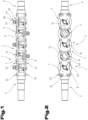
- a variant of a straightening rotor 1 or components thereof is shown in various views.
- the straightening rotor 1 is used to straighten wire, for example for producing reinforcements for concrete. Since such straightening rotors are known from the prior art, reference is made to the relevant prior art for further features of the straightening rotor 1 not described below.
- the wire can have a diameter between 4 mm and 24 mm. This information is for clarification purposes only and should not be understood as limiting.
- the wire can also be thicker.
- the straightening rotor 1 has a rotor housing 2 that can be rotatably mounted, i.e. is rotatably mounted in a straightening machine, in which several straightening element units 4, for example between three and ten, in particular between three and five, straightening element units 4, are arranged one behind the other and spaced apart from one another in a feed direction 3 of the wire.
- the straightening rotor 1 also has a rotor inlet element 5, through which the wire to be straightened is fed to the straightening rotor 1, and a rotor outlet element 6, through which the straightened wire exits the straightening rotor 1.
- the straightening rotor 1 can also consist of the components mentioned.
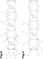
- the rotor housing 2 has or consists of a first rotor plate 7 (also referred to as first housing plate), a second rotor plate 8 (also referred to as second housing plate) and several spacer elements 9 for arranging the first and second rotor plates 7, 8 at a distance from one another.
- the first and/or the second rotor plate 7, 8 can be cuboid-shaped.
- the first and/or the second rotor plate 7, 8 are designed to be lightweight.
- the first rotor plate 7 has three fastening sections 10 and the second rotor plate 8 has two.
- the straightening element units 4 are connected to both the first and the second rotor plate 7, 8.
- this embodiment can also be used for straightening elements formed by straightening rollers. straightening elements can be provided.
- straightening element units 4 are only connected to the first or only to the second rotor plate 7, 8, and further straightening element units 4 are connected to both the first and the second rotor plate 7, 8.
- the extent of the reduction of the width 12 in relation to the maximum width 11 of the first and/or second rotor plate 7, 8 depends - in addition to mechanical requirements - on the size and fastening of the straightening element units 4.
- the reduced width 12 can be between 5% and 50% of the maximum width 11.
- first and/or second rotor plate 7, 8 can have one or more tapers, relative to the maximum width 11 of the respective rotor plate 7 or 8.
- the spacer elements 9 preferably have no chamfers (at the transitions to the end faces) in order to improve the stabilizing effect.
- the spacer elements 9 can, for example, have a diameter of between 12 mm and 25 mm at the widest point and/or a diameter of between 9 mm and 15 mm at the narrowest point. Cylindrical spacer elements 9 can have a diameter of between 8 mm and 20 mm, in particular between 10 mm and 16 mm. In the case of polygonal cross-sectional shapes, this is the diameter of the smallest enveloping circle of the cross-sectional area.
- the straightening elements 13 can be straightening nozzles or straightening stones. Such straightening elements 13 are known from the prior art. In the preferred embodiment, however, the straightening elements 13 are straightening rollers, as can be seen from the Fig. 1 and 2
- the straightening rollers can be designed as straight rollers (cylindrical rollers) or hyperpolar rollers, etc. Barrel-shaped rollers are also possible, although this is not preferred.
- the straightening element units 4 each have only one straightening element 13 in the form of a straightening roller.
- Fig. 9 to 11 show a preferred embodiment of the straightening element unit 4, as it can be used in particular together with the rotor housing in the straightening rotor 1.
- the straightening element unit 4 comprises a straightening element 13 in the form of a straightening roller 34.
- the straightening roller 34 is rotatably mounted via at least one bearing element 35.
- the bearing element 35 is preferably a roller bearing, in particular a ball bearing, but can also be a plain bearing.
- the bearing element 35 is arranged in a bearing receptacle 36 of the straightening roller 34.
- the straightening element unit 4 also has a bearing fork 37 for supporting a bearing axis 38.
- the straightening roller 34 is rotatably arranged on the bearing axis 38.
- the bearing axis 38 can extend through the straightening roller 34 for this purpose.
- the straightening element unit 4 can also consist of the components mentioned. If the straightening element unit 4 is used in the rotor housing 2 described above, it is arranged between the first and the second rotor plate 7, 8 and connected to the first or second rotor plate 7, 8.
- At least one bearing element 35 is a permanently lubricated (lifetime lubricated) bearing element 35.
- a lubricating grease is used as the lubricant for this purpose, which is contained in the bearing element 35 and does not escape from the bearing element 35 under normal operating conditions.
- the bearing element 35 is sealed accordingly.
- Permanently lubricated rolling bearings are known from the relevant prior art, so that further discussion is unnecessary. Their usability in the straightening element unit 4 or in a straightening rotor 1 is surprising, however, since relatively large forces act on the bearing elements during straightening, so that up to now work has been carried out with bearing elements that have to be regreased or repeatedly relubricated, also in order to avoid overheating of the bearing elements.
- a permanently lubricated bearing element 35 can also be used without shortening the service life of the straightening roller 34. In particular, this also contributes when the straightening element unit 4 is used in combination with the rotor housing 2 described above.
- the outer diameter 39 can be 38 mm for a wire diameter of 6 mm to 12 mm, 42 mm for a wire diameter of 12 mm to 14 mm, or 54 mm to 56 or to 62 mm for a wire diameter of 14 mm to 16 mm.
- the bearing fork 37 can be designed in one piece. In the preferred embodiment, however, the bearing fork 37 is designed in several parts, in particular comprising a base element 40 and two column-shaped eyebolts or eye nuts 41, which are connected to the base element 40 via fastening means or consist thereof.
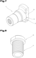
- FIG. 12 A variant of a foot element 40 is shown in Fig. 12
- This foot element 40 is designed as a plate-shaped foot plate. It has a circular cross-section.
- the foot element 40 can also have a different shape, for example an elliptical or oval cross-sectional area or front surface, as shown in Fig. 12 indicated by dashed lines, or a triangular, square, hexagonal, octagonal or generally polygonal cross-sectional area or frontal area.
- the straightening element unit 4 is connected to the rotor housing 2 via the base element 40, in particular to the first or second rotor plate 7, 8.
- the base element 40 has at least one opening 42 (in particular a bore), which is arranged in particular centrally.
- the opening 42 is preferably provided with an internal thread into which a fastening element, in particular cooperating with a height adjustment element 44 (see Fig. 18 ), is screwed in.
- the base element 40 also has two further openings 45 for the connection with the eye nuts 41 or eye bolts.
- these are an internal thread of the openings 45.
- the connection is made via, in particular countersunk, screws 46, which are screwed into an internal thread of the eye nuts 41, as can be seen from Fig. 11 is evident.
- the foot element 40 can also have at least one recess 47 in which a pin 48 (see Fig. 2 ) which extends from the first or second rotor plate 7, 8 or the rotor housing 2 in the direction of the base element 40.
- the recess 47 extends in the axial direction continuously through the base element 40 and in the radial direction starting at the outer circumference of the base element 40 inwards. The position of the axis of the straightening roller 34 in relation to the feed direction 3 can be determined or adjusted using the pin 48.
- the angle of the inclination of the axes of the straightening roller 34 is determined exclusively by screws.
- the pin 48 can therefore be dispensed with.
- the angle can be determined by reducing the tolerances in this area, in particular the fastening of the base element 40 (by matching the openings for the screws for fastening the base element 40 in the rotor plates 7, 8 to the screws, in particular Allen screws). This also makes a more compact design of the straightening rotor 1 possible.
- a dome-shaped extension 49 can be provided in the area of the central opening 42, which can be accommodated in a corresponding recess in the rotor housing 2, in particular the first or second rotor plate 7, 8. It is thus possible to increase the axial length of the internal thread 43 or to create a better or mechanically more stable attachment of the base element 40 to the rotor housing 2.
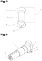
- a variant of an eye nut 41 is shown.
- the eye nut 41 has a first widened end section 50 with an opening 51 for receiving the position axis 38.
- the eye nut also has a tapered middle section 52 and a foot section 53 that is widened in comparison thereto.
- the widened foot section 53 can improve the connection of the eye nut 41 (or the eye bolt) to the foot element 40.
- the tapered middle section 52 allows the straightening roller 34 to be arranged closer to the eye nut 42 (or the eye bolt), as can be seen in particular from Fig. 11 is visible. It is advantageous if the end section 50 of the eye nut 41 (or the eye bolt) is not or not significantly wider than the middle section 52 (in the direction of the bearing axis 38).
- the length of the middle section 52 can be adapted to the diameter of the straightening roller 34.
- FIG. 15 A variant of a bearing axis 38 is shown.
- This can be cylindrical, with a bore 54 with an internal thread for receiving a screw 55 (see Fig. 11 ), with which the bearing axle 38 is connected to the eye nut 41 or the eye bolt or generally to the leg of the bearing fork 37.
- the bearing axle 38 can have a central section 56 with a larger diameter (compared to the adjoining end sections) (in Fig. 15 shown in dashed lines), in which at least one bearing element 35 is arranged.
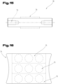
- the straightening element unit 4 it can be provided that more than one bearing element 35 is arranged between the straightening roller 34 and the bearing axis 38, in particular two or three bearing elements 35, as can be seen from Fig. 16 can be seen. These bearing elements 35 are arranged one behind the other in the axial direction through the straightening roller 34. Two of the bearing elements 35 can be in direct contact with each other. According to another embodiment, however, an annular web 57 (also referred to as a beard) can be arranged between at least two bearing elements 35, in particular continuously running in the circumferential direction.
- the annular web 57 extends in the bearing receptacle 36 of the straightening roller 34 from a bearing receiving surface 58 in the radial direction inwards and thus protrudes beyond the bearing receiving surface 58. It is possible that the annular web 57 is placed in such a way or is designed such that it allows a series of bearing elements 35 without spacing.
- the axial width of the ring web 57 can be adjusted accordingly. If necessary, the ring web 57 can be so wide that it serves as a contact surface, i.e. as a further bearing receiving surface for a bearing element 35 with a smaller diameter.
- the ring web 57 is arranged centrally or eccentrically in the bearing holder 36 of the straightening roller 34.
- the ring web 57 is preferably formed integrally with the straightening roller 34.
- At least one bearing element 35 is arranged in the axial direction protruding over the straightening roller 34 (see Fig. 11 ). This makes it possible to make the foot section 53 of the eye nut 41 or the eye bolt wider. This also allows the straightening element unit 4 to be built narrower, which means that the weight of the straightening element unit can be reduced. This in turn has a positive effect on the mass inertia of the straightening rotor 1.
- the straightening roller 34 is preferably made of steel.
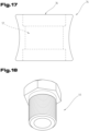
- Fig. 18 The height adjustment element 44 (also referred to as a dressing sleeve) is shown. As can be seen in particular from Fig. 1 As can be seen, after the height position of the straightening roller 34 has been adjusted in relation to the wire to be straightened, the height adjustment element 44 is clamped against the rotor housing 2 with a lock nut 59 (which can be referred to as a counter nut). A fastening element, in particular a screw 60, extends through the height adjustment element 33 and is screwed into the foot element 40 of the bearing fork 37 and is clamped against the height adjustment element 44.
- a lock nut 59 which can be referred to as a counter nut
- the total length of the height adjustment element 44 in its axial direction can preferably be selected such that a zero position (wire only touches the straightening element 13, in particular the straightening roller 34, without overbending) is achieved when the height adjustment element 44 is completely screwed in. This can simplify the setting of the correct height.
- the height adjustment of the straightening roller 34 can also be carried out differently.
- the straightening rotor 1 and/or the straightening element unit 4 described above can be used in a straightening machine for wire (not shown).
- the straightening machine can also have a cutting device so that bars, in particular reinforcing bars for concrete, can also be produced.
- a coating in particular a PVD coating, can be provided at least on the surface of the straightening element 13 that is in contact with the wire, in particular the outer surface of the straightening roller 34. This also makes it possible to prevent the straightening element 13 from overheating.
- the coating can be, for example, a nitride coating, such as TiN or TiN-based, TiCN or TiCN-based, TiAlN or TiAlN-based, CrN or CrN-based, CrCN or CrCN-based, ZrN or ZrN-based, aluminum titanium chromium nitride, aluminum chromium nitride, AlCr-based, AlTiSi-based, ZrCN-based, WC-C-based.
- a nitride coating such as TiN or TiN-based, TiCN or TiCN-based, TiAlN or TiAlN-based, CrN or CrN-based, CrCN or CrCN-based, ZrN or ZrN-based, aluminum titanium chromium nitride, aluminum chromium nitride, AlCr-based, AlTiSi-based, ZrCN-based, WC-C-based.
- the embodiments show or describe possible design variants of the straightening rotor 1, the straightening rotor housing 2 and the straightening element unit 4, whereby it should be noted at this point that combinations of the individual design variants are also possible.
- the straightening element unit 4 described can be an independent invention independent of the rotor housing 2.
- a straightening element unit 4 with a straightening roller 34 which has a coating, in particular a PVD coating, on at least part or the entire outer surface that comes into contact with the wire, which reduces the slip between the wire and the straightening roller 34, can be an independent invention.
Landscapes
- Engineering & Computer Science (AREA)
- Mechanical Engineering (AREA)
- General Engineering & Computer Science (AREA)
- Ropes Or Cables (AREA)
- Rollers For Roller Conveyors For Transfer (AREA)
Applications Claiming Priority (1)
| Application Number | Priority Date | Filing Date | Title |
|---|---|---|---|
| ATA50552/2023A AT527341A1 (de) | 2023-07-13 | 2023-07-13 | Richtrotor |
Publications (2)
| Publication Number | Publication Date |
|---|---|
| EP4491295A2 true EP4491295A2 (fr) | 2025-01-15 |
| EP4491295A3 EP4491295A3 (fr) | 2025-05-07 |
Family
ID=91924206
Family Applications (1)
| Application Number | Title | Priority Date | Filing Date |
|---|---|---|---|
| EP24188101.0A Pending EP4491295A3 (fr) | 2023-07-13 | 2024-07-11 | Rotor de redressage |
Country Status (2)
| Country | Link |
|---|---|
| EP (1) | EP4491295A3 (fr) |
| AT (1) | AT527341A1 (fr) |
Citations (5)
| Publication number | Priority date | Publication date | Assignee | Title |
|---|---|---|---|---|
| DE8528959U1 (de) | 1985-10-11 | 1985-12-12 | Sommer Maschinenfabrik GmbH, 8300 Landshut | Vorrichtung zum Richten von auf Rollen gewickeltem Stahldraht, insbesondere Betonstahl |
| DE3910221A1 (de) | 1989-03-30 | 1990-10-04 | Peddinghaus Carl Ullrich Dr | Richtmaschine fuer draht, insbesondere fuer betonstahldraht |
| DE102007026728A1 (de) | 2007-02-02 | 2008-08-07 | Schumag Ag | Richtrotor, Rotorrichter sowie Richtverfahren |
| AT11798U1 (de) | 2008-03-28 | 2011-05-15 | Progress Maschinen & Automation Ag | Rotorrichteinheit zum richten von baustahldraht |
| DE102013201551B3 (de) | 2013-01-30 | 2014-02-27 | Wafios Ag | Richtmaschine für Draht |
Family Cites Families (9)
| Publication number | Priority date | Publication date | Assignee | Title |
|---|---|---|---|---|
| US5042280A (en) * | 1990-04-11 | 1991-08-27 | Anagnostopoulos Panayotis A | Machine for straightening metallic bars or rods or wires or tubes |
| DE19723635C2 (de) * | 1997-06-05 | 1999-03-25 | Witels App Masch Albert Gmbh | Abspulrichter für draht- oder mehrdrahtförmiges Gut |
| JP2000005821A (ja) * | 1998-06-22 | 2000-01-11 | Fuji Xerox Co Ltd | 円筒状金属管の矯正装置、および前記矯正装置で矯正された円筒状金属管 |
| DE102004057427A1 (de) * | 2004-11-27 | 2006-06-01 | Sms Demag Ag | Vorrichtung und Verfahren zum Stranggießen |
| KR20100024011A (ko) * | 2008-08-25 | 2010-03-05 | (주)아나스틸 | 직선교정장치 및 이를 이용한 직선교정 시스템 |
| CN102777489A (zh) * | 2012-07-30 | 2012-11-14 | 江苏万达特种轴承有限公司 | 一种支架用侧向滚轮轴承 |
| CN213968402U (zh) * | 2020-11-28 | 2021-08-17 | 常熟市和新不锈钢管制造有限公司 | 一种减少钢管磨损的矫直机 |
| CN113059085A (zh) * | 2021-02-25 | 2021-07-02 | 苏文进 | 一种建筑机械加工用钢筋拉直截断一体机 |
| CN217044391U (zh) * | 2022-04-06 | 2022-07-26 | 付江 | 一种钢筋调直机调直轮组件 |
-
2023
- 2023-07-13 AT ATA50552/2023A patent/AT527341A1/de unknown
-
2024
- 2024-07-11 EP EP24188101.0A patent/EP4491295A3/fr active Pending
Patent Citations (5)
| Publication number | Priority date | Publication date | Assignee | Title |
|---|---|---|---|---|
| DE8528959U1 (de) | 1985-10-11 | 1985-12-12 | Sommer Maschinenfabrik GmbH, 8300 Landshut | Vorrichtung zum Richten von auf Rollen gewickeltem Stahldraht, insbesondere Betonstahl |
| DE3910221A1 (de) | 1989-03-30 | 1990-10-04 | Peddinghaus Carl Ullrich Dr | Richtmaschine fuer draht, insbesondere fuer betonstahldraht |
| DE102007026728A1 (de) | 2007-02-02 | 2008-08-07 | Schumag Ag | Richtrotor, Rotorrichter sowie Richtverfahren |
| AT11798U1 (de) | 2008-03-28 | 2011-05-15 | Progress Maschinen & Automation Ag | Rotorrichteinheit zum richten von baustahldraht |
| DE102013201551B3 (de) | 2013-01-30 | 2014-02-27 | Wafios Ag | Richtmaschine für Draht |
Non-Patent Citations (2)
| Title |
|---|
| ANONYMOUS: "Progress-Richtrolle", PROGRESS-RICHTROLLE, 29 March 2013 (2013-03-29), pages 1, XP093260177 |
| ANONYMOUS: "Progress-Richtrotor", PROGRESS-RICHTROTOR, 28 February 2013 (2013-02-28), pages 1, XP093260167 |
Also Published As
| Publication number | Publication date |
|---|---|
| AT527341A1 (de) | 2025-01-15 |
| EP4491295A3 (fr) | 2025-05-07 |
Similar Documents
| Publication | Publication Date | Title |
|---|---|---|
| DE69502550T2 (de) | Profilanpassung für Vielwalzengerüste | |
| EP2276600B1 (fr) | Fraise à queue présentant différents angles d'inclinaison | |
| EP0282090A1 (fr) | Fraise à plaquettes | |
| DE3005579A1 (de) | Lineare kugellagereinheit | |
| DE3401634C2 (fr) | ||
| EP0295449A2 (fr) | Dispositif pour imprimer ou découper à l'emporte-pièce une bande | |
| EP4105506A1 (fr) | Segment de cage pour une cage de palier à rouleaux | |
| EP1256637A1 (fr) | Porte-pièce | |
| DE2115868A1 (de) | Gewindekörper sowie Verfahren und Vorrichtung zu seiner Herstellung | |
| EP1711288A1 (fr) | Dispositif d'assemblage | |
| EP3093119A1 (fr) | Vis d'extrudeuse et procede de sa reequipement | |
| EP3735541B1 (fr) | Dispositif de fixation | |
| DE3013410A1 (de) | Fuehrungssystem fuer lineare bewegungen | |
| EP4491295A2 (fr) | Rotor de redressage | |
| DE3445219C2 (de) | Walzenkalibrierung für kontinuierlich arbeitende Stab- und Drahtwalzstraßen bzw. -blöcke | |
| EP0332801B1 (fr) | Appareil pour changer la forme de coupe d'ébauches de boites | |
| EP1468754A2 (fr) | Dispositif de fixation au moins un rouleau d'une machine de roulage | |
| DE102016100599B4 (de) | Schmiedemaschine und Schmiedeverfahren | |
| DE10144743B4 (de) | Walzgerüst zum Walzen von stab- oder rohrförmigem Gut | |
| EP3738691A2 (fr) | Outil de roulage en plusieurs parties comprenant un palier flottant et machine de roulage | |
| DE1477040A1 (de) | Werkzeughalter fuer Walzwerkzeuge | |
| DE102017214897B4 (de) | Anstellbares Walzgerüst für das Walzen von stabförmigem Walzgut mit einer asymmetrischen Verzahnung zwischen den Exzenterbuchsen sowie Exzenterbuchse mit asymmetrischer Verzahnung | |
| EP1790423B1 (fr) | Dispositif de retenue des au moins deux rouleaux d'une machine de roulage et machine de roulage | |
| DE6920874U (de) | Spielfrei stellbares, kombiniertes radial-axial-einspur-waelzlager | |
| DE2435916B2 (de) | Vorschub-dreheinrichtung eines pilgerschrittwalzwerkes |
Legal Events
| Date | Code | Title | Description |
|---|---|---|---|
| PUAI | Public reference made under article 153(3) epc to a published international application that has entered the european phase |
Free format text: ORIGINAL CODE: 0009012 |
|
| STAA | Information on the status of an ep patent application or granted ep patent |
Free format text: STATUS: THE APPLICATION HAS BEEN PUBLISHED |
|
| AK | Designated contracting states |
Kind code of ref document: A2 Designated state(s): AL AT BE BG CH CY CZ DE DK EE ES FI FR GB GR HR HU IE IS IT LI LT LU LV MC ME MK MT NL NO PL PT RO RS SE SI SK SM TR |
|
| TPAC | Observations filed by third parties |
Free format text: ORIGINAL CODE: EPIDOSNTIPA |
|
| PUAL | Search report despatched |
Free format text: ORIGINAL CODE: 0009013 |
|
| AK | Designated contracting states |
Kind code of ref document: A3 Designated state(s): AL AT BE BG CH CY CZ DE DK EE ES FI FR GB GR HR HU IE IS IT LI LT LU LV MC ME MK MT NL NO PL PT RO RS SE SI SK SM TR |
|
| RIC1 | Information provided on ipc code assigned before grant |
Ipc: F16C 13/02 20060101ALI20250328BHEP Ipc: F16C 13/00 20060101ALI20250328BHEP Ipc: B21F 1/02 20060101AFI20250328BHEP |
|
| STAA | Information on the status of an ep patent application or granted ep patent |
Free format text: STATUS: REQUEST FOR EXAMINATION WAS MADE |
|
| 17P | Request for examination filed |
Effective date: 20251104 |
|
| GRAP | Despatch of communication of intention to grant a patent |
Free format text: ORIGINAL CODE: EPIDOSNIGR1 |
|
| STAA | Information on the status of an ep patent application or granted ep patent |
Free format text: STATUS: GRANT OF PATENT IS INTENDED |