EP4491297A1 - Stanznietwerkzeug, stanznietwerkzeug und verfahren zur herstellung eines stanznietgelenks - Google Patents
Stanznietwerkzeug, stanznietwerkzeug und verfahren zur herstellung eines stanznietgelenks Download PDFInfo
- Publication number
- EP4491297A1 EP4491297A1 EP23184342.6A EP23184342A EP4491297A1 EP 4491297 A1 EP4491297 A1 EP 4491297A1 EP 23184342 A EP23184342 A EP 23184342A EP 4491297 A1 EP4491297 A1 EP 4491297A1
- Authority
- EP
- European Patent Office
- Prior art keywords
- punch
- base
- rivet
- riveting
- annular wall
- Prior art date
- Legal status (The legal status is an assumption and is not a legal conclusion. Google has not performed a legal analysis and makes no representation as to the accuracy of the status listed.)
- Pending
Links
Images

Classifications
-
- B—PERFORMING OPERATIONS; TRANSPORTING
- B21—MECHANICAL METAL-WORKING WITHOUT ESSENTIALLY REMOVING MATERIAL; PUNCHING METAL
- B21J—FORGING; HAMMERING; PRESSING METAL; RIVETING; FORGE FURNACES
- B21J15/00—Riveting
- B21J15/02—Riveting procedures
- B21J15/04—Riveting hollow rivets mechanically
- B21J15/041—Riveting hollow rivets mechanically by pushing a drive-pin
-
- B—PERFORMING OPERATIONS; TRANSPORTING
- B21—MECHANICAL METAL-WORKING WITHOUT ESSENTIALLY REMOVING MATERIAL; PUNCHING METAL
- B21J—FORGING; HAMMERING; PRESSING METAL; RIVETING; FORGE FURNACES
- B21J15/00—Riveting
- B21J15/10—Riveting machines
-
- B—PERFORMING OPERATIONS; TRANSPORTING
- B21—MECHANICAL METAL-WORKING WITHOUT ESSENTIALLY REMOVING MATERIAL; PUNCHING METAL
- B21J—FORGING; HAMMERING; PRESSING METAL; RIVETING; FORGE FURNACES
- B21J15/00—Riveting
- B21J15/02—Riveting procedures
- B21J15/025—Setting self-piercing rivets
-
- B—PERFORMING OPERATIONS; TRANSPORTING
- B21—MECHANICAL METAL-WORKING WITHOUT ESSENTIALLY REMOVING MATERIAL; PUNCHING METAL
- B21J—FORGING; HAMMERING; PRESSING METAL; RIVETING; FORGE FURNACES
- B21J15/00—Riveting
- B21J15/10—Riveting machines
- B21J15/30—Particular elements, e.g. supports; Suspension equipment specially adapted for portable riveters
-
- B—PERFORMING OPERATIONS; TRANSPORTING
- B21—MECHANICAL METAL-WORKING WITHOUT ESSENTIALLY REMOVING MATERIAL; PUNCHING METAL
- B21J—FORGING; HAMMERING; PRESSING METAL; RIVETING; FORGE FURNACES
- B21J15/00—Riveting
- B21J15/10—Riveting machines
- B21J15/36—Rivet sets, i.e. tools for forming heads; Mandrels for expanding parts of hollow rivets
-
- F—MECHANICAL ENGINEERING; LIGHTING; HEATING; WEAPONS; BLASTING
- F16—ENGINEERING ELEMENTS AND UNITS; GENERAL MEASURES FOR PRODUCING AND MAINTAINING EFFECTIVE FUNCTIONING OF MACHINES OR INSTALLATIONS; THERMAL INSULATION IN GENERAL
- F16B—DEVICES FOR FASTENING OR SECURING CONSTRUCTIONAL ELEMENTS OR MACHINE PARTS TOGETHER, e.g. NAILS, BOLTS, CIRCLIPS, CLAMPS, CLIPS OR WEDGES; JOINTS OR JOINTING
- F16B19/00—Bolts without screw-thread; Pins, including deformable elements; Rivets
- F16B19/04—Rivets; Spigots or the like fastened by riveting
- F16B19/08—Hollow rivets; Multi-part rivets
Definitions
- the present application relates to self-piercing riveting (SPR) technologies. More specifically, the present application relates to dies used in during the installation of self-piercing rivets.
- SPR self-piercing riveting
- Self-pierce riveting is a high-speed mechanical fastening process for joining two or more sheets of material without a predrilled or punched hole.
- SPR processes are conducted by driving a semi-hollow rivet through an uppermost workpiece layer and upsetting the rivet in a lowermost workpiece layer to form a durable mechanical joint.
- the hollow shank of the rivet widen radially and hereby creates an undercut that results in permanent joining of the workpieces. The end of the shank does not completely pierce the lowermost workpiece and does not protrude from the workpiece arrangement.
- the lowermost workpiece layer is supported at a die.
- the die is arranged opposite to a punch adapted to drive the rivet into the workpiece arrangement.
- die There are different shapes and geometries of die, which can depend on the workpiece materials, rivet material and/or geometry, ... but also the kind of joint to be achieved.
- the die plays an important role in the formation of a robust joint.
- EP2872270A1 from the applicant for instance discloses a die comprising a basic body, which has a recess for forming an underside of a punch-rivet joint, the recess having a base and an annular wall.
- An annular radial-flow inhibiting device is realized in a central region of the base, which inhibiting device limits a radial material flow out of the inner region of the annular radial-flow inhibiting device.
- Such dies allow to realize joints which are axially compact and robust.
- EP3423211A1 discloses a die comprising the following features: a main body having an upper side and a recess formed therein.
- the recess comprises an annular demolding section arranged radially outwardly, a subsequent or adjacent annular channel section and a centrally arranged die bottom, wherein in a cross section of the self-piercing riveting die extending parallel to the central axis a demolding inclination of the demolding section encloses with the upper side of the self-piercing riveting die an angle ⁇ in the range of 5° ⁇ 45°.
- the present invention provides a punch-riveting die according to claim 1. More particularly, the punch-riveting die is for a punch-riveting tool for setting a semi-hollow punch rivet with a rivet shank inner diameter into a punch rivet joint.
- the punch-riveting die comprises a basic body with a sheet metal support surface and a recess for forming an underside of a punch-rivet joint, the recess is arranged rotationally symmetrically to the central axis of the punch-riveting die, the recess having a first annular base, a second annular base and a central cavity extending axially below the second base of the recess.
- a projection is realized in the central part of the cavity and a first annular wall extends between the first base and the sheet metal support surface, a second annular wall extends between the first base and the second base, and a third annular wall extends between the second base and the bottom of the cavity.
- the projection within the cavity is such that a ring groove is formed.
- the present geometry with three levels allows the joining between high strength steel or ultra-high strength steel and brittle cast aluminium for instance without the formation of cracks or without altering the performance of the joint.
- the cavity is such that the rivet compresses as little as possible and can form a sufficient undercut.
- the first annular base is inclined with respect to the plane defined by the sheet metal support surface. This improves the material intake to avoid cracks and increase the die volume.
- the first annular base is curved.
- the first annular base comprises a convex flow barrier.
- the flow barrier positively influences the material behavior and reduces the tensions on the rivet, the die and workpieces.
- the first annular base comprises a first end connected to the first annular wall and a second end opposite the first end and connected to the second annular wall, and wherein the second end is a rounded section, and wherein the second end is above the first end.
- the rounded section forms the convex flow barrier.
- the second end is above the first end, which means that the second end is in the axial direction closer from the sheet metal support surface than the first end.
- the second annular base is inclined such that its end in the vicinity of the cavity is axially above the first end.
- the second annular base forms a ramp.
- the first annular wall is realized in the manner of a truncated-cone surface.
- the second annular wall is realized in the manner of a truncated-cone surface.
- the third annular wall is realized in the manner of a truncated cone-surface.
- the first annular wall has a first tapered angle
- the second annular wall has a second tapered angle, the second tapered angle being smaller than the first tapered angle.
- the first and second annular walls with the tapered angle allows a better demolding.
- the bottom of the cavity comprises a concave flow barrier.
- the flow barrier positively influences the material behavior and reduces the tensions on the rivet, the die and workpieces.
- the present invention is also directed to a punch-riveting tool for setting a semi-hollow punch rivet into a punch rivet joint, the punch-riveting tool comprising:
- the punch-riveting tool is adapted to perform self-piercing riveting joints a with workpiece made of brittle material without decreasing the joint properties.
- the present invention is also directed to a method for producing a punch-rivet joint of at least two workpieces, which are disposed on the top side of a punch-riveting die as described above, comprising the step of driving a semi-hollow punch rivet into the uppermost workpiece, a hollow shank of the semi-hollow punch rivet also penetrating into the lowermost workpiece and widening radially therein, an underside of the punch-rivet joint being formed by the punch-riveting die.
- the uppermost workpiece is made of a high strength steel or ultra-high strength steel, and wherein the lowermost workpiece is made of brittle cast aluminum.
- the geometry of the die limits or avoids the creation of cracks within the rivet or the workpieces during the setting.
- the uppermost workpiece has a first thickness Tw, wherein the recess has an axial depth TA between the sheet metal support surface and the second base, and wherein the axial depth TA is in the range Tw ⁇ TA ⁇ 1,5Tw, and in particular is in the range Tw ⁇ TA ⁇ 1,35Tw.
- the undercut remains axially compact.
- the rivet has a rivet shank diameter Dr and the second annular wall has a second recess diameter DA2, and wherein the second recess diameter DA2 is in the range 0,8Dr ⁇ DA2 ⁇ 1,2Dr. This contributes to the compactness of the undercut and the limitation of cracks and stress within the materials of the rivet and the workpieces.
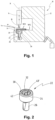
- Fig. 1 schematically shows a punch-riveting tool 10.
- the punch-riveting tool 10 comprises a frame 12, also called C-frame. At one end of the frame 12, in a known manner a carriage 14 is mounted so as to be displaceable along a longitudinal axis X (punching axis).
- a punch 16 for performing a punch-riveting process is disposed on the carriage 14.
- a punch rivet 18 is held by means of a holding device.
- the frame 12 further comprises at a second end, opposite the first end, a punch-riveting die receiver 20 for receiving a punch-riveting die 22.
- the punch-riveting die 22 has a basic body 24 and has a die shank 26, of a lesser diameter, extending axially therefrom.
- the die shank 26 is adapted to be receive in an opening of the die receiver 20.
- a radial surface at the transition between the basic body 24 and the shank 26 bears on a shoulder 28 of the die receiver 20.
- the basic body 24 is preferably rotationally symmetrical in form.
- the punch-riveting die 22, and more particularly the basic body 24, comprises a sheet metal support surface 30 which forms a first axial side.
- the sheet metal support surface 30, when the die 22 is mounted within the die receiver 20, is adapted to face towards the punch 16.
- the sheet metal support surface 30 is adapted to support workpiece layers destined to be joined.
- two or more workpieces W1, W2 in the form of sheets are disposed between the punch 16 and the die 22, and more particularly are supported by the sheet metal support surface 30 of the die 22. Further, it is possible to fix the workpiece stack in position with regard to the sheet metal support surface 30.
- the punch 16 is then moved downwards along the longitudinal axis X, such that the rivet 18 can be driven into the workpiece arrangement.
- a hollow shank of the punch rivet 18 in this case deforms radially within the workpieces and is deflected radially outwards, as a result of which a non-positive and/or positive joint is produced between the workpieces.
- the sheet metal support surface 30 comprises a recess 32 (see Fig. 2 ).
- the recess 32 is arranged rotationally symmetrically to the central axis of the punch-riveting die.
- the recess has a first annular base 34, a second annular base 36 and a central cavity 38 extending axially below the second annular base 36.
- the central cavity 38 is provided with a projection 40.
- the projection 40 is arranged in the central part of the central cavity 38.
- the central cavity 38 with the projection defines a ring groove.
- the first annular base 34 extends axially below the sheet metal support surface 30.
- the second annular base 36 extends axially below the first annular base 34.
- the first annular base extends axially between the sheet metal support surface 30 and the second annular base.
- a first annular wall 42 extends between the sheet metal support surface 30 and the first annular base 34.
- the first annular wall connects the sheet metal support surface 30 and the first annular base.
- the first annular wall is realized in the manner of a truncated-cone surface.
- a second annular wall 44 extends between the first annular base 32 and the second annular base 36.
- the second annular wall connects the first annular base and the second annular base.
- the second annular wall is realized in the manner of a truncated-cone surface.
- the first annular wall 42 has a first tapered angle A1.
- the first tapered angle A1 may be between 35 and 80 degrees.
- the second annular wall 44 has a second tapered angle A2.
- the second tapered angle A2 may be between 5 and 45 degrees.
- the second tapered angle is smaller than the first tapered angle.
- a third annular wall 46 extends between the second annular base and the recess.
- the third annular wall connects the second annular base and the recess.
- the third annular wall is realized in the manner of a truncated-cone surface.
- the third annular wall may have a tapered angle substantially similar to the second tapered angle A2.
- the sheet metal support surface 30 extends along a plane which is sensibly horizontal.
- the first annular base 34 is inclined with respect to the plane defined by the sheet metal support surface 30.
- the first annular base 32 may also be slightly curved.
- the first annular base 32 comprises a convex flow barrier CXF.
- the convex flow barrier prevents the brittle material from cracking at the shank of the rivet.
- the first annular wall 42 comprises a first end 48 and a second end 50.
- the first end 48 contacts the first annular wall.
- the second end 50 contacts the second annular wall.
- the second end is a rounded section.
- the second end 50 extends axially above the first end 48.
- the first annular base 34 forms a ramp which extends from the first end to the second end, wherein the second end is closer from the sheet metal support surface than the first end.
- the ramp and/or the rounded section may form the convex flow barrier CXF.
- the second annular base 34 comprises a first end contacting the second annular wall and a second end contacting the third annular wall.
- the first end and the second end are for instance are essentially on the same plane or level, such that the axial distance between the first end and the sheet metal support surface and the axial distance between the second end and the sheet metal support surface are identical or substantially identical.
- the second end may also have a rounded portion.
- the second annular base 36 extends in a plane sensibly parallel to the plane of the sheet metal support surface 30.
- the bottom of the cavity 38 comprises for instance a concave flow barrier CCF.
- the concave flow barrier CCF reduces the stress in the die and provides additional volume for the deformed material.
- the concave flow barrier is for instance formed by the ring groove.
- the projection 40 may extend axially at the same height than the second annular base or may be axially slightly above the second annular base.
- the projection is for instance a rounded projection.
- the workpieces are first stacked and arranged on the sheet metal support surface 30 of the die.
- a semi-hollow punch rivet is driven with the punch into the uppermost workpiece.
- a hollow shank of the semi-hollow punch rivet penetrates into the lowermost workpiece and widens radially therein.
- the underside of the punch-rivet joint is then formed by the punch-riveting die.
- the uppermost workpiece is made of a high strength steel or ultra-high strength steel and the lowermost workpiece is made of brittle cast aluminum. More generally, at least one of the workpiece is made of a brittle material like cast aluminum.
- the uppermost workpiece W2 has a first thickness Tw.
- the recess 32 has an axial depth TA between the sheet metal support surface 30 and the second annular base.
- the axial depth TA is in the range Tw ⁇ TA ⁇ 1,5Tw, and in particular is in the range Tw ⁇ TA ⁇ 1,35Tw.
- the rivet has a rivet shank diameter Dr and the second annular wall has a second recess diameter DA2.
- the second recess diameter DA2 is in the range 0,8Dr ⁇ DA2 ⁇ 1,2Dr.
Landscapes
- Engineering & Computer Science (AREA)
- Mechanical Engineering (AREA)
- General Engineering & Computer Science (AREA)
- Insertion Pins And Rivets (AREA)
- Connection Of Plates (AREA)
Priority Applications (5)
| Application Number | Priority Date | Filing Date | Title |
|---|---|---|---|
| EP23184342.6A EP4491297A1 (de) | 2023-07-10 | 2023-07-10 | Stanznietwerkzeug, stanznietwerkzeug und verfahren zur herstellung eines stanznietgelenks |
| KR1020240087296A KR20250009354A (ko) | 2023-07-10 | 2024-07-03 | 펀치 리벳팅 다이, 펀치 리벳팅 도구 및 펀치 리벳 조인트의 제조 방법 |
| CN202410915831.5A CN119282013A (zh) | 2023-07-10 | 2024-07-09 | 冲铆模具、冲铆工具及用于产生冲铆接头的方法 |
| US18/768,591 US20250018460A1 (en) | 2023-07-10 | 2024-07-10 | Punch-riveting die, punch-riveting tool and method for producing a punch-rivet joint |
| JP2024110735A JP2025016430A (ja) | 2023-07-10 | 2024-07-10 | パンチリベット結合用金型、パンチリベット結合用工具及びパンチリベット接合部の形成方法 |
Applications Claiming Priority (1)
| Application Number | Priority Date | Filing Date | Title |
|---|---|---|---|
| EP23184342.6A EP4491297A1 (de) | 2023-07-10 | 2023-07-10 | Stanznietwerkzeug, stanznietwerkzeug und verfahren zur herstellung eines stanznietgelenks |
Publications (1)
| Publication Number | Publication Date |
|---|---|
| EP4491297A1 true EP4491297A1 (de) | 2025-01-15 |
Family
ID=87202120
Family Applications (1)
| Application Number | Title | Priority Date | Filing Date |
|---|---|---|---|
| EP23184342.6A Pending EP4491297A1 (de) | 2023-07-10 | 2023-07-10 | Stanznietwerkzeug, stanznietwerkzeug und verfahren zur herstellung eines stanznietgelenks |
Country Status (5)
| Country | Link |
|---|---|
| US (1) | US20250018460A1 (de) |
| EP (1) | EP4491297A1 (de) |
| JP (1) | JP2025016430A (de) |
| KR (1) | KR20250009354A (de) |
| CN (1) | CN119282013A (de) |
Citations (9)
| Publication number | Priority date | Publication date | Assignee | Title |
|---|---|---|---|---|
| JPH03210931A (ja) * | 1990-01-16 | 1991-09-13 | Multifastener Corp | 自己ピアシング・リベッティング・ファスナのパネルへの取付け法及び自己ピアシング・リベッティング・ファスナのパネルへの取付け用ダイ部材 |
| WO2002002259A1 (en) * | 2000-06-30 | 2002-01-10 | Ariel Industries Plc | Controlled flow of displaced material in self-pierce fastening |
| WO2007147551A1 (de) * | 2006-06-21 | 2007-12-27 | Sumanjit Singh | Stanzniet und matrize |
| WO2011023616A1 (en) * | 2009-08-24 | 2011-03-03 | Newfrey Llc | Punch rivet, method for producing a punch rivet connection, and workpiece arrangement |
| WO2014009129A1 (en) * | 2012-07-13 | 2014-01-16 | Newfrey Llc | Punch-riveting die and punch-riveting method |
| WO2017148684A1 (de) * | 2016-03-04 | 2017-09-08 | Böllhoff Verbindungstechnik GmbH | Stanznietmatrize |
| WO2018194021A1 (ja) * | 2017-04-17 | 2018-10-25 | マツダ株式会社 | リベット接合用金型 |
| JP2018176237A (ja) * | 2017-04-17 | 2018-11-15 | マツダ株式会社 | リベット接合用金型 |
| EP4035794A1 (de) * | 2021-02-02 | 2022-08-03 | Toyota Jidosha Kabushiki Kaisha | Verbindungsvorrichtung, verbindungsverfahren und verbundene struktur |
Family Cites Families (4)
| Publication number | Priority date | Publication date | Assignee | Title |
|---|---|---|---|---|
| DE102008024938A1 (de) * | 2008-05-23 | 2009-11-26 | Dr. Ing. H.C. F. Porsche Aktiengesellschaft | Stanznietwerkzeug |
| US8458881B1 (en) * | 2011-11-22 | 2013-06-11 | Ford Global Technologies, Llc | Die with multi-sided cavity for self-piercing riveting process |
| JP2013169567A (ja) * | 2012-02-21 | 2013-09-02 | Nippon Pop Rivets & Fasteners Ltd | 自己穿孔型リベット用ダイ |
| JP2021115574A (ja) * | 2020-01-22 | 2021-08-10 | 株式会社三五 | セルフピアスリベット接合用金型 |
-
2023
- 2023-07-10 EP EP23184342.6A patent/EP4491297A1/de active Pending
-
2024
- 2024-07-03 KR KR1020240087296A patent/KR20250009354A/ko active Pending
- 2024-07-09 CN CN202410915831.5A patent/CN119282013A/zh active Pending
- 2024-07-10 US US18/768,591 patent/US20250018460A1/en active Pending
- 2024-07-10 JP JP2024110735A patent/JP2025016430A/ja active Pending
Patent Citations (11)
| Publication number | Priority date | Publication date | Assignee | Title |
|---|---|---|---|---|
| JPH03210931A (ja) * | 1990-01-16 | 1991-09-13 | Multifastener Corp | 自己ピアシング・リベッティング・ファスナのパネルへの取付け法及び自己ピアシング・リベッティング・ファスナのパネルへの取付け用ダイ部材 |
| WO2002002259A1 (en) * | 2000-06-30 | 2002-01-10 | Ariel Industries Plc | Controlled flow of displaced material in self-pierce fastening |
| WO2007147551A1 (de) * | 2006-06-21 | 2007-12-27 | Sumanjit Singh | Stanzniet und matrize |
| WO2011023616A1 (en) * | 2009-08-24 | 2011-03-03 | Newfrey Llc | Punch rivet, method for producing a punch rivet connection, and workpiece arrangement |
| WO2014009129A1 (en) * | 2012-07-13 | 2014-01-16 | Newfrey Llc | Punch-riveting die and punch-riveting method |
| EP2872270A1 (de) | 2012-07-13 | 2015-05-20 | Newfrey LLC | Stanznietstempel und stanznietverfahren |
| WO2017148684A1 (de) * | 2016-03-04 | 2017-09-08 | Böllhoff Verbindungstechnik GmbH | Stanznietmatrize |
| EP3423211A1 (de) | 2016-03-04 | 2019-01-09 | Böllhoff Verbindungstechnik GmbH | Stanznietmatrize |
| WO2018194021A1 (ja) * | 2017-04-17 | 2018-10-25 | マツダ株式会社 | リベット接合用金型 |
| JP2018176237A (ja) * | 2017-04-17 | 2018-11-15 | マツダ株式会社 | リベット接合用金型 |
| EP4035794A1 (de) * | 2021-02-02 | 2022-08-03 | Toyota Jidosha Kabushiki Kaisha | Verbindungsvorrichtung, verbindungsverfahren und verbundene struktur |
Also Published As
| Publication number | Publication date |
|---|---|
| KR20250009354A (ko) | 2025-01-17 |
| CN119282013A (zh) | 2025-01-10 |
| US20250018460A1 (en) | 2025-01-16 |
| JP2025016430A (ja) | 2025-02-04 |
Similar Documents
| Publication | Publication Date | Title |
|---|---|---|
| US9091290B2 (en) | Punch rivet and die | |
| US9919356B2 (en) | Punch-riveting die | |
| US8763233B2 (en) | Punch rivet, method for producing a punch rivet connection, and workpiece arrangement | |
| JP5972225B2 (ja) | 自己挿通リベットを用いた締結部形成方法 | |
| US11833576B2 (en) | Riveting method | |
| JP6909321B2 (ja) | 半中空パンチリベット、半中空パンチリベットによる少なくとも2つの要素のパンチリベットジョイント、及び少なくとも2つの要素を半中空パンチリベットで連結する方法 | |
| WO2016128080A1 (en) | Punch rivet and method for producing a punch-riveted joint | |
| JP3543267B2 (ja) | アルミ製打込みリベット | |
| US20050120532A1 (en) | Method, device and auxiliary joining element for joining at least two parts | |
| EP4491297A1 (de) | Stanznietwerkzeug, stanznietwerkzeug und verfahren zur herstellung eines stanznietgelenks | |
| CN114251339A (zh) | 带槽自冲铆钉 | |
| CN111237310A (zh) | 实心冲压铆钉、借助其的至少两部件的冲压铆钉接合件和用其连接多个部件的方法 | |
| CN114160743B (zh) | 一种自冲铆连接装置及其铆接方法 | |
| CN118401759A (zh) | 自冲铆钉 | |
| EP3633215A1 (de) | Stanzniet | |
| EP3829796A1 (de) | Verfahren und vorrichtung zum einsetzen von nieten | |
| US20220090620A1 (en) | Self-piercing rivet |
Legal Events
| Date | Code | Title | Description |
|---|---|---|---|
| PUAI | Public reference made under article 153(3) epc to a published international application that has entered the european phase |
Free format text: ORIGINAL CODE: 0009012 |
|
| STAA | Information on the status of an ep patent application or granted ep patent |
Free format text: STATUS: THE APPLICATION HAS BEEN PUBLISHED |
|
| AK | Designated contracting states |
Kind code of ref document: A1 Designated state(s): AL AT BE BG CH CY CZ DE DK EE ES FI FR GB GR HR HU IE IS IT LI LT LU LV MC ME MK MT NL NO PL PT RO RS SE SI SK SM TR |
|
| STAA | Information on the status of an ep patent application or granted ep patent |
Free format text: STATUS: REQUEST FOR EXAMINATION WAS MADE |
|
| 17P | Request for examination filed |
Effective date: 20250605 |
|
| GRAP | Despatch of communication of intention to grant a patent |
Free format text: ORIGINAL CODE: EPIDOSNIGR1 |
|
| STAA | Information on the status of an ep patent application or granted ep patent |
Free format text: STATUS: GRANT OF PATENT IS INTENDED |
|
| RIC1 | Information provided on ipc code assigned before grant |
Ipc: B21J 15/00 20060101AFI20260107BHEP Ipc: B21J 15/36 20060101ALI20260107BHEP |
|
| INTG | Intention to grant announced |
Effective date: 20260120 |