EP4491468A1 - Procédé de détection d'un dysfonctionnement d'une soupape - Google Patents
Procédé de détection d'un dysfonctionnement d'une soupape Download PDFInfo
- Publication number
- EP4491468A1 EP4491468A1 EP24182472.1A EP24182472A EP4491468A1 EP 4491468 A1 EP4491468 A1 EP 4491468A1 EP 24182472 A EP24182472 A EP 24182472A EP 4491468 A1 EP4491468 A1 EP 4491468A1
- Authority
- EP
- European Patent Office
- Prior art keywords
- valve
- pressure
- brake
- state variable
- transmission section
- Prior art date
- Legal status (The legal status is an assumption and is not a legal conclusion. Google has not performed a legal analysis and makes no representation as to the accuracy of the status listed.)
- Pending
Links
Images


Classifications
-
- B—PERFORMING OPERATIONS; TRANSPORTING
- B60—VEHICLES IN GENERAL
- B60T—VEHICLE BRAKE CONTROL SYSTEMS OR PARTS THEREOF; BRAKE CONTROL SYSTEMS OR PARTS THEREOF, IN GENERAL; ARRANGEMENT OF BRAKING ELEMENTS ON VEHICLES IN GENERAL; PORTABLE DEVICES FOR PREVENTING UNWANTED MOVEMENT OF VEHICLES; VEHICLE MODIFICATIONS TO FACILITATE COOLING OF BRAKES
- B60T17/00—Component parts, details, or accessories of power brake systems not covered by groups B60T8/00, B60T13/00 or B60T15/00, or presenting other characteristic features
- B60T17/18—Safety devices; Monitoring
- B60T17/22—Devices for monitoring or checking brake systems; Signal devices
-
- B—PERFORMING OPERATIONS; TRANSPORTING
- B60—VEHICLES IN GENERAL
- B60T—VEHICLE BRAKE CONTROL SYSTEMS OR PARTS THEREOF; BRAKE CONTROL SYSTEMS OR PARTS THEREOF, IN GENERAL; ARRANGEMENT OF BRAKING ELEMENTS ON VEHICLES IN GENERAL; PORTABLE DEVICES FOR PREVENTING UNWANTED MOVEMENT OF VEHICLES; VEHICLE MODIFICATIONS TO FACILITATE COOLING OF BRAKES
- B60T17/00—Component parts, details, or accessories of power brake systems not covered by groups B60T8/00, B60T13/00 or B60T15/00, or presenting other characteristic features
- B60T17/18—Safety devices; Monitoring
- B60T17/22—Devices for monitoring or checking brake systems; Signal devices
- B60T17/221—Procedure or apparatus for checking or keeping in a correct functioning condition of brake systems
-
- B—PERFORMING OPERATIONS; TRANSPORTING
- B60—VEHICLES IN GENERAL
- B60T—VEHICLE BRAKE CONTROL SYSTEMS OR PARTS THEREOF; BRAKE CONTROL SYSTEMS OR PARTS THEREOF, IN GENERAL; ARRANGEMENT OF BRAKING ELEMENTS ON VEHICLES IN GENERAL; PORTABLE DEVICES FOR PREVENTING UNWANTED MOVEMENT OF VEHICLES; VEHICLE MODIFICATIONS TO FACILITATE COOLING OF BRAKES
- B60T13/00—Transmitting braking action from initiating means to ultimate brake actuator with power assistance or drive; Brake systems incorporating such transmitting means, e.g. air-pressure brake systems
- B60T13/10—Transmitting braking action from initiating means to ultimate brake actuator with power assistance or drive; Brake systems incorporating such transmitting means, e.g. air-pressure brake systems with fluid assistance, drive, or release
-
- B—PERFORMING OPERATIONS; TRANSPORTING
- B60—VEHICLES IN GENERAL
- B60T—VEHICLE BRAKE CONTROL SYSTEMS OR PARTS THEREOF; BRAKE CONTROL SYSTEMS OR PARTS THEREOF, IN GENERAL; ARRANGEMENT OF BRAKING ELEMENTS ON VEHICLES IN GENERAL; PORTABLE DEVICES FOR PREVENTING UNWANTED MOVEMENT OF VEHICLES; VEHICLE MODIFICATIONS TO FACILITATE COOLING OF BRAKES
- B60T13/00—Transmitting braking action from initiating means to ultimate brake actuator with power assistance or drive; Brake systems incorporating such transmitting means, e.g. air-pressure brake systems
- B60T13/10—Transmitting braking action from initiating means to ultimate brake actuator with power assistance or drive; Brake systems incorporating such transmitting means, e.g. air-pressure brake systems with fluid assistance, drive, or release
- B60T13/66—Electrical control in fluid-pressure brake systems
- B60T13/662—Electrical control in fluid-pressure brake systems characterised by specified functions of the control system components
-
- B—PERFORMING OPERATIONS; TRANSPORTING
- B60—VEHICLES IN GENERAL
- B60T—VEHICLE BRAKE CONTROL SYSTEMS OR PARTS THEREOF; BRAKE CONTROL SYSTEMS OR PARTS THEREOF, IN GENERAL; ARRANGEMENT OF BRAKING ELEMENTS ON VEHICLES IN GENERAL; PORTABLE DEVICES FOR PREVENTING UNWANTED MOVEMENT OF VEHICLES; VEHICLE MODIFICATIONS TO FACILITATE COOLING OF BRAKES
- B60T13/00—Transmitting braking action from initiating means to ultimate brake actuator with power assistance or drive; Brake systems incorporating such transmitting means, e.g. air-pressure brake systems
- B60T13/10—Transmitting braking action from initiating means to ultimate brake actuator with power assistance or drive; Brake systems incorporating such transmitting means, e.g. air-pressure brake systems with fluid assistance, drive, or release
- B60T13/66—Electrical control in fluid-pressure brake systems
- B60T13/68—Electrical control in fluid-pressure brake systems by electrically-controlled valves
- B60T13/683—Electrical control in fluid-pressure brake systems by electrically-controlled valves in pneumatic systems or parts thereof
-
- B—PERFORMING OPERATIONS; TRANSPORTING
- B60—VEHICLES IN GENERAL
- B60T—VEHICLE BRAKE CONTROL SYSTEMS OR PARTS THEREOF; BRAKE CONTROL SYSTEMS OR PARTS THEREOF, IN GENERAL; ARRANGEMENT OF BRAKING ELEMENTS ON VEHICLES IN GENERAL; PORTABLE DEVICES FOR PREVENTING UNWANTED MOVEMENT OF VEHICLES; VEHICLE MODIFICATIONS TO FACILITATE COOLING OF BRAKES
- B60T13/00—Transmitting braking action from initiating means to ultimate brake actuator with power assistance or drive; Brake systems incorporating such transmitting means, e.g. air-pressure brake systems
- B60T13/10—Transmitting braking action from initiating means to ultimate brake actuator with power assistance or drive; Brake systems incorporating such transmitting means, e.g. air-pressure brake systems with fluid assistance, drive, or release
- B60T13/66—Electrical control in fluid-pressure brake systems
- B60T13/68—Electrical control in fluid-pressure brake systems by electrically-controlled valves
- B60T13/686—Electrical control in fluid-pressure brake systems by electrically-controlled valves in hydraulic systems or parts thereof
-
- B—PERFORMING OPERATIONS; TRANSPORTING
- B60—VEHICLES IN GENERAL
- B60T—VEHICLE BRAKE CONTROL SYSTEMS OR PARTS THEREOF; BRAKE CONTROL SYSTEMS OR PARTS THEREOF, IN GENERAL; ARRANGEMENT OF BRAKING ELEMENTS ON VEHICLES IN GENERAL; PORTABLE DEVICES FOR PREVENTING UNWANTED MOVEMENT OF VEHICLES; VEHICLE MODIFICATIONS TO FACILITATE COOLING OF BRAKES
- B60T13/00—Transmitting braking action from initiating means to ultimate brake actuator with power assistance or drive; Brake systems incorporating such transmitting means, e.g. air-pressure brake systems
- B60T13/74—Transmitting braking action from initiating means to ultimate brake actuator with power assistance or drive; Brake systems incorporating such transmitting means, e.g. air-pressure brake systems with electrical assistance or drive
- B60T13/745—Transmitting braking action from initiating means to ultimate brake actuator with power assistance or drive; Brake systems incorporating such transmitting means, e.g. air-pressure brake systems with electrical assistance or drive acting on a hydraulic system, e.g. a master cylinder
-
- B—PERFORMING OPERATIONS; TRANSPORTING
- B60—VEHICLES IN GENERAL
- B60T—VEHICLE BRAKE CONTROL SYSTEMS OR PARTS THEREOF; BRAKE CONTROL SYSTEMS OR PARTS THEREOF, IN GENERAL; ARRANGEMENT OF BRAKING ELEMENTS ON VEHICLES IN GENERAL; PORTABLE DEVICES FOR PREVENTING UNWANTED MOVEMENT OF VEHICLES; VEHICLE MODIFICATIONS TO FACILITATE COOLING OF BRAKES
- B60T8/00—Arrangements for adjusting wheel-braking force to meet varying vehicular or ground-surface conditions, e.g. limiting or varying distribution of braking force
- B60T8/32—Arrangements for adjusting wheel-braking force to meet varying vehicular or ground-surface conditions, e.g. limiting or varying distribution of braking force responsive to a speed condition, e.g. acceleration or deceleration
- B60T8/88—Arrangements for adjusting wheel-braking force to meet varying vehicular or ground-surface conditions, e.g. limiting or varying distribution of braking force responsive to a speed condition, e.g. acceleration or deceleration with failure responsive means, i.e. means for detecting and indicating faulty operation of the speed responsive control means
- B60T8/885—Arrangements for adjusting wheel-braking force to meet varying vehicular or ground-surface conditions, e.g. limiting or varying distribution of braking force responsive to a speed condition, e.g. acceleration or deceleration with failure responsive means, i.e. means for detecting and indicating faulty operation of the speed responsive control means using electrical circuitry
-
- B—PERFORMING OPERATIONS; TRANSPORTING
- B60—VEHICLES IN GENERAL
- B60T—VEHICLE BRAKE CONTROL SYSTEMS OR PARTS THEREOF; BRAKE CONTROL SYSTEMS OR PARTS THEREOF, IN GENERAL; ARRANGEMENT OF BRAKING ELEMENTS ON VEHICLES IN GENERAL; PORTABLE DEVICES FOR PREVENTING UNWANTED MOVEMENT OF VEHICLES; VEHICLE MODIFICATIONS TO FACILITATE COOLING OF BRAKES
- B60T2270/00—Further aspects of brake control systems not otherwise provided for
- B60T2270/40—Failsafe aspects of brake control systems
- B60T2270/402—Back-up
-
- B—PERFORMING OPERATIONS; TRANSPORTING
- B60—VEHICLES IN GENERAL
- B60T—VEHICLE BRAKE CONTROL SYSTEMS OR PARTS THEREOF; BRAKE CONTROL SYSTEMS OR PARTS THEREOF, IN GENERAL; ARRANGEMENT OF BRAKING ELEMENTS ON VEHICLES IN GENERAL; PORTABLE DEVICES FOR PREVENTING UNWANTED MOVEMENT OF VEHICLES; VEHICLE MODIFICATIONS TO FACILITATE COOLING OF BRAKES
- B60T2270/00—Further aspects of brake control systems not otherwise provided for
- B60T2270/40—Failsafe aspects of brake control systems
- B60T2270/403—Brake circuit failure
-
- B—PERFORMING OPERATIONS; TRANSPORTING
- B60—VEHICLES IN GENERAL
- B60T—VEHICLE BRAKE CONTROL SYSTEMS OR PARTS THEREOF; BRAKE CONTROL SYSTEMS OR PARTS THEREOF, IN GENERAL; ARRANGEMENT OF BRAKING ELEMENTS ON VEHICLES IN GENERAL; PORTABLE DEVICES FOR PREVENTING UNWANTED MOVEMENT OF VEHICLES; VEHICLE MODIFICATIONS TO FACILITATE COOLING OF BRAKES
- B60T2270/00—Further aspects of brake control systems not otherwise provided for
- B60T2270/40—Failsafe aspects of brake control systems
- B60T2270/406—Test-mode; Self-diagnosis
-
- B—PERFORMING OPERATIONS; TRANSPORTING
- B60—VEHICLES IN GENERAL
- B60T—VEHICLE BRAKE CONTROL SYSTEMS OR PARTS THEREOF; BRAKE CONTROL SYSTEMS OR PARTS THEREOF, IN GENERAL; ARRANGEMENT OF BRAKING ELEMENTS ON VEHICLES IN GENERAL; PORTABLE DEVICES FOR PREVENTING UNWANTED MOVEMENT OF VEHICLES; VEHICLE MODIFICATIONS TO FACILITATE COOLING OF BRAKES
- B60T2270/00—Further aspects of brake control systems not otherwise provided for
- B60T2270/40—Failsafe aspects of brake control systems
- B60T2270/413—Plausibility monitoring, cross check, redundancy
Definitions
- the present invention relates to a method for detecting a malfunction of a valve of a braking device for a work machine.
- the present invention also relates to a control device for a braking device of a work machine, which is designed to carry out such a method, and to a braking device with such a control device.
- Braking systems for work machines are often operated with pneumatic pressure and controlled by valves.
- DE 10 2019 100 869 A1 For example, a braking device for controlling the braking pressure of a trailer of a work machine is known.
- the braking devices of the work machines can have redundant components, for example redundant valves, to increase safety. To ensure smooth operation, it is necessary that the valves of such a braking device function as intended.
- the object of the present invention was therefore to provide a method for detecting a malfunction of a valve of a braking device.
- the present invention relates to a method for detecting a malfunction of a valve of a braking device for a work machine.
- the work machine can have a towing vehicle and additionally a trailer.
- the towing vehicle can be, for example, a tractor or a wheel loader.
- the trailer can be a vehicle which does not have its own drive and is pulled by another vehicle, for example the towing vehicle.
- the braking device can be designed to brake the work machine, for example a towing vehicle and alternatively or additionally a trailer of the work machine.
- the braking device can initiate such braking by pneumatic pressure, hydraulic pressure, a mechanical component, for example a piston, and/or an electrical component, for example an electric motor.
- the braking device can be designed to initiate braking via a wireless connection.
- the braking device can be operatively connected to a brake which can brake a towing vehicle and alternatively or additionally a trailer of the work machine.
- the braking device is arranged in a towing vehicle of the work machine and designed to actuate a brake of a trailer of the work machine.
- the braking device is designed to actuate a brake, for example the brake described above, via the valve and a transmission section.
- the transmission section can be a section which provides an operative connection between the valve and the brake.
- the transmission section can provide a direct or indirect connection between the valve and the brake.
- the transmission section can have mechanical, pneumatic or hydraulic connecting elements, for example hoses or further valves. Applying the brake can involve either closing or opening the brake.
- the valve of the braking device can be designed as a solenoid valve, for example as a 3/2-way solenoid valve or as a 2/2-way solenoid valve.
- the valve can be controlled pneumatically or hydraulically.
- the valve can be designed to transmit a hydraulic or pneumatic pressure, via which a brake of the working machine can be actuated directly or indirectly.
- a malfunction of the valve can be a limited functionality of the valve, which can be accompanied by an impairment of the braking functionality of the braking device.
- a malfunction of the valve can be caused by the valve, the control of the valve or the lines that lead to and from the valve.
- a malfunction of the valve can manifest itself in the fact that the valve does not respond correctly when controlled.
- a malfunction of the valve can include the valve jamming, not opening or not closing.
- a malfunction of the valve can be caused by a leak in the valve and alternatively or additionally by a line leading away from or to the valve.
- a malfunction of the valve can manifest itself in the passage of too high or too low a pressure or too high or too low a mass flow.
- the method includes controlling the valve of the braking device, for example to open or close the valve.
- the valve can be controlled electronically, mechanically, pneumatically or hydraulically, for example. By controlling the valve, a connection of various inputs and outputs of the valve can be initiated.
- the valve can be controlled in response to a braking signal, which can be triggered by a driver and alternatively or additionally by a control device of the work machine.
- the method also includes determining, for example measuring, a state variable in the transmission section.
- the state variable can be a pressure, a temperature, a speed, a mass flow density, a density, a heat flow, an electrical parameter and/or a magnetic parameter.
- the state variable is determined in the transmission section, for example by means of one or more sensors.
- the method comprises a step of comparing the determined state variable with a reference variable.
- the reference variable can be a fixed or adjustable variable.
- the reference variable can specify an upper or lower limit for the state variable, whereby a state variable above the upper limit or a state variable below the lower limit can indicate a malfunction.
- the reference variable can also comprise a range of values, whereby a state variable outside the range of values can indicate a malfunction.
- the comparison can comprise determining whether a state variable is greater than, less than, or equal to the reference variable.
- the comparison can comprise subtracting the state variable from the reference variable, or the reference variable from the state variable.
- the comparison can comprise determining the distance of a state variable from the reference variable.
- the comparison can also comprise determining an output value of a function which has the state variable as an input value.
- the method includes a step of detecting a malfunction of the valve based on a result of the comparison of the determined state variable with the reference variable.
- the detection can include forwarding and, for example, outputting an error signal.
- the error signal can be forwarded and output to a driver and alternatively or additionally to a component of the work machine, for example the control device.
- a control device can take corrective measures, for example, issue a warning signal or adjust braking operation.
- the method described therefore enables a malfunction of a valve of a braking device of a work machine to be detected in a simple manner.
- Valves can represent safety-critical components of a braking device. By comparing a state variable in the transmission section, a malfunction can be detected quickly, precisely and inexpensively.
- the braking device has a further valve for actuating the brake via a further transmission section.
- One brake can thus be actuated via two valves. If only one of the valves controls the brake, the brake can be actuated. If both valves control the brake, the brake can be actuated.
- the further transmission section can be designed completely or partially separately from the transmission section. However, the further transmission section can also partially coincide with the transmission section. Both transmission sections can therefore have at least partially a common section. With regard to the design of the further valve and the further transmission section, reference is made to the above explanations regarding the valve and the transmission section.
- the method comprises a step of further controlling the further valve of the braking device.
- the further controlling of the further valve can be carried out independently of the controlling of the valve.
- the further controlling of the further valve can also be coupled with the controlling of the valve, for example correspond to it.
- the method of this embodiment further comprises a step of further determining a further state variable in the further transmission section.
- the further determination can take place simultaneously or at a different time from the first determination.
- the further determination can take place using the same or a different device as the determination.
- the further state variable can be a different state variable than or the same state variable as the state variable.
- the method of this embodiment further comprises a step of further comparing the determined further state variable with a reference variable.
- the comparison of the further state variable can use a different reference value or the same reference value for the comparison, as is the case when comparing the state variable.
- the method of this embodiment further comprises a step of further detecting a malfunction of the further valve based on a result of the further comparison.
- the method of this embodiment is therefore also suitable for detecting malfunctions of a braking device with at least two valves, which are designed as redundant valves, for example. Safe operation of the braking device can be ensured by two valves.
- the braking device can be set up so that the additional valve can control a braking function if the first valve shows a malfunction.
- the braking device can also be set up so that the first valve can control a braking function if the additional valve shows a malfunction.
- a redundant configuration can be operated reliably and safely.
- the additional control, additional determination, additional comparison and additional detection can be carried out together with the control, determination, comparison and detection in a single test cycle. Alternatively, they are carried out in a separate test cycle, which can follow a test cycle in which the other steps are carried out.
- a test cycle can always be carried out when a parking brake function is actuated.
- the transmission section and the further transmission section have a common transmission section.
- the state variable and the further state variable are determined in this common transmission section.
- a common section can have a pneumatic, hydraulic or other line to which both valves are connected.
- the two transmission sections can be brought together via a shuttle valve in order to form the common transmission section behind the shuttle valve. If the two transmission sections are brought together before being connected to the brake, they can have a common transmission section.
- the step of determining and the step of further determining a state variable comprise determining a state variable in the common transmission section. The step of determining and the step of further determining can take place simultaneously or at different times. By determining the state variables in the common transmission section, the number of components can be reduced.
- the transmission section and the further transmission section in which the state variable and the further state variable are determined are designed separately from one another.
- the variables can be determined using a sensor device directly behind the respective valve.
- the step of further controlling the further valve takes place after the valve has been controlled.
- the further controlling can be carried out after the control has been carried out.
- the further controlling can also be started after the start of the control, but before the control is no longer carried out.
- the controlling can take place a predetermined time after the first controlling.
- the further controlling of the further valve can take place after the first controlling by a time offset from which an effect of the first controlling is to be expected.
- a further controlling can take place after the first controlling by a time offset from which a change in the determined state variable, for example a pressure drop or pressure increase is to be expected.
- the time between activation and subsequent activation can be 100 to 1000 milliseconds.
- the time between activation and subsequent activation can be between 0 and 1 second or more than 1 second.
- detecting a malfunction of the valve includes detecting whether the determined state variable is greater than the reference variable. If a state variable has multiple dimensions, a greater can be greater than a single one or all dimensions of the state variable. By detecting whether the determined state variable is greater than a reference variable, a particularly simple and reliable method for detecting a malfunction is achieved.
- the reference variable can be the maximum brake pressure at which a brake is opened. If the determined state variable is greater than this reference variable, the brake cannot be opened and there is a malfunction. A malfunction can be detected particularly reliably using such a reference variable.
- determining a state variable in the transmission section includes determining a pressure in the transmission section. Determining a pressure can be done via a pressure sensor. Determining via a pressure sensor can be done directly on the transmission section. Determining via a pressure sensor can be done via a pressure line that is operatively connected to the transmission section. Determining a pressure can also be done via a model calculation. Determining a pressure can be done, for example, by determining a speed and a temperature. The speed and temperature can be input variables of a calculation model that has the determined pressure as an output variable.
- a pressure can be a total pressure, static pressure or dynamic pressure.
- a pressure can also be a partial pressure of a component of a fluid.
- the effect of one or more valves on a pressure-controlled brake can be determined particularly easily, quickly, precisely and reliably. Detecting a malfunction can therefore be particularly easy, quickly, precisely and reliably. Determining a pressure can be particularly cost-effective by using a pressure sensor, for example by using an existing pressure sensor in the braking device.
- the state variable is determined with a waiting time after activation.
- a waiting time can be between 100 and 1000 milliseconds long.
- a waiting time can be between 0 and 1 second long or more than 1 second.
- a waiting time can be a time that elapses between activation and the determination of the state variable.
- the time between the determination and the activation can be shorter than the time between an activation and a subsequent activation.
- the braking device has a parking brake module with the valve for parking braking the working machine and a service brake module for service braking the working machine.
- the parking brake module can comprise at least one valve.
- the parking brake module can comprise two valves, for example the valve described above and the further valve described above, which can be connected redundantly, for example.
- a parking brake module can be a module of the braking device which is designed to initiate parking braking.
- the parking brake module can be controlled by a control device.
- a parking brake can prevent the working machine from rolling away when it is parked.
- a service brake module can be a module of the braking device which is designed to initiate service braking.
- the service brake module can be controlled by a control device
- a service brake can be a braking action when the working machine is in motion, which can be initiated by a driver using a brake lever or brake pedal, for example.
- the parking brake module and the service brake module can control the same brake.
- the service brake module can influence the determined state variable in the transmission section, for example by increasing or decreasing it.
- the method of this embodiment includes a step of checking whether the service brake module is being operated above a limit value.
- Operating the service brake module above the limit value can be accompanied by the service brake module outputting a value above a limit value, which, for example, has an influence on the state variable in the transmission section that is above a limit value.
- the limit value can relate to an input variable or an output variable of the service module.
- the limit value can also relate to a value within the service brake module.
- the limit value can relate to an internal pressure of the service brake module.
- the limit value can be a pressure, a temperature, a speed, a mass, a mass flow and/or another state variable.
- the present method is only carried out if the service brake module is not operated above the limit value.
- the present invention further relates to a control device for a braking device of a work machine, which is set up, i.e. specifically prepared, for example programmed, to carry out the method according to one of the embodiments described above.
- the control device can be part of the braking device or can be provided separately from it.
- the control device can have one or more interfaces in order to communicate with the different components of the braking device to carry out the method, for example via a CAN bus.
- the control device can have one or more components that can be provided at the same or different locations.
- the present invention further relates to a braking device for a work machine with such a control device.
- the braking device can have a housing in which all components of the braking device can be arranged.
- Fig. 1 schematically illustrates a braking device 10 for a work machine according to an embodiment of the present invention.
- the braking device 10 has a service brake module 70, a parking brake module 40, a redundancy module 90, a brake 14, a control device 16 and a housing 20.
- the brake 14 is designed to brake a work machine. In the present embodiment, the brake 14 is arranged in a trailer of the work machine and designed to brake it.
- the braking device 10 is supplied with pneumatic pressure via a pressure input line 26 and a pressure output line 28.
- the pneumatic pressure in the braking device 10 can be released via a vent line 32 and a silencer 34.
- the service brake module 70, the parking brake module 40 and the redundancy module 90 are designed to actuate the brake 14 with pneumatic pressure via the brake pressure output line 22.
- the brake pressure output line 22 forms at least part of a transmission section and a further transmission section.
- the braking device 10 further comprises a first relay valve 24, a breakaway valve 30 and a brake changeover valve 36.
- the first relay valve 24 is designed to pass a pressure to the brake pressure output line 22 depending on the service brake module 70 and the parking brake module 40.
- the first relay valve 24 passes a pressure when the service brake module 70 applies a pressure to the valve 24 and in turn does not pass a pressure when the parking brake module 40 applies a pressure to the valve 24.
- the breakaway valve 30 connects the pressure input line 26 to the pressure output line 28 and is controlled via a control pressure line 86 of the service brake. In the event of a leak in the pneumatic system, it throttles a fluid flow in order to avoid a sudden drop in pressure.
- the parking brake module 40 is designed to control the first relay valve 24 via a first input 63, a first parking brake valve 46 and a second parking brake valve 56 and thus to provide a parking brake function.
- the service brake module 70 is designed to control the first relay valve 24 via a second input 87 depending on a brake signal from the work machine in order to brake the trailer of the work machine during operation.
- the service brake module 70 is designed to determine a brake pressure in the brake pressure output line 22 via a sensor pressure line 78 via a pressure sensor 76.
- the redundancy module 90 is designed to Redundancy valve 102 and a second relay valve 96 provide a redundant braking function.
- a hydraulic input line 92 is provided, via which the brake 14 can be controlled in the event of a malfunction of the service brake module 70.
- the control device 16 is designed to control the parking brake module 40 via a first parking plug socket 42 and a second parking plug socket 52.
- the control device 16 is also designed to control the service brake module 70 via an operating plug socket 72.
- the control device 16 is also designed to receive signals from the pressure sensor 76 of the service brake module 70 via the operating plug socket 72 and thus determine a pressure in the brake pressure output line 22.
- the parking brake module 40 has the first parking brake valve 46 and the second parking brake valve 56, which are connected in parallel and are each designed as a 3/2-way solenoid valve.
- the first parking brake valve 46 can be adjusted via the first parking plug socket 42 and a first valve electronics 44 by means of the control device 16.
- the first parking brake valve 46 is connected to a shuttle valve 60 of the parking brake module 40 via a first brake control line 48.
- the second parking brake valve 56 can be adjusted via the second parking plug socket 52 and a second valve electronics 54 by means of the control device 16.
- the second parking brake valve 56 is connected to the shuttle valve 60 via a second brake control line 58.
- the shuttle valve 60 is designed to pass on a pressure when a pressure is present on at least one of the first brake control line 48 and the second brake control line 58.
- the first parking brake valve 46 and the second parking brake valve 56 are open when energized and closed when de-energized.
- first parking brake valve 46 When the first parking brake valve 46 is open, it passes a pressure from the pressure input line 26 to the first brake control line 48.
- second parking brake valve 56 When the second parking brake valve 56 is open, it passes a pressure from the pressure input line 26 to the second brake control line 58.
- the shuttle valve 60 is connected to the first relay valve 24 via a control pressure line 62 of the parking brake module 40 and the first input 63.
- the first relay valve 24 is designed to forward a pneumatic pressure from the pressure input line 26 to the brake change valve 36 when there is no pressure at the first input 63.
- the brake change valve 36 is designed to forward a pressure to the brake pressure output line 22 and thus the brake 14 when there is pressure at at least one of the inputs of the brake change valve 36.
- the parking brake module 40 thus has a redundant control of the parking brake function, since in the event of a malfunction of the parking brake valve 46 or 56, the other parking brake valve 46 or 56 continues to provide a parking brake function.
- the service brake module 70 has the service plug socket 72, brake electronics 74, the pressure sensor 76, a pilot valve 80, an outlet valve 82 and an inlet valve 84.
- the service brake module 70 is connected to the first relay valve 24 via the control pressure line 86 and the second input 87.
- the first relay valve 24 is designed to forward a pneumatic pressure from the pressure input line 26 to the brake change valve 36 when pressure is present at the second input 87.
- the pilot valve 80 is designed as a 3/2-way solenoid valve.
- the pilot valve 80 is designed to forward a pneumatic pressure to the redundancy module 90 in the event of a malfunction of the service brake module 70. In an energized state, it connects a redundancy valve control line 100 to the vent line 32.
- a de-energized state it connects the pressure input line 26 to the redundancy valve control line 100 and thus passes a pressure on to the redundancy valve 102.
- the de-energized state of the pilot valve 80 can occur in the event of a malfunction of the service brake module 70.
- the outlet valve 82 is designed as a 2/2-way solenoid valve.
- the outlet valve 82 is open in the de-energized state and closed in the energized state.
- the inlet valve 84 is designed as a 2/2-way solenoid valve and is open in the energized state and closed in the de-energized state.
- the outlet valve 82 and the inlet valve 84 are connected to the pressure input line 26 and the vent line 32.
- the inlet valve 84 is designed to release a pressure from the pressure input line 26 via the Control pressure line 86 to the second input 87 of the first relay valve 24 and thus to control braking.
- the outlet valve 82 is designed to release the pressure of the control pressure line 86 in a non-energized state via the vent line 32 when braking is no longer controlled.
- the redundancy module 90 has the hydraulic input line 92 and a hydraulic sensor pressure line 94 for hydraulic control.
- the redundancy module 90 also has the second relay valve 96, a redundancy brake pressure line 98 and the redundancy valve 102.
- the second relay valve 96 is connected to the redundancy valve 102 via a pressure line 104 of the second relay valve 96.
- the redundancy valve 102 is designed to be open in a pressurized state. In doing so, it passes a pressure from the pressure input line 26 via the break-off valve 30 to the pressure line 104 of the second relay valve 96.
- the redundancy valve 102 is designed as a 3/2-way valve.
- the redundancy valve 102 is controlled via the redundancy valve control line 100, which is connected to the pilot valve 80.
- the redundancy valve 102 is designed to vent the pressure line 104 via the vent line 32 in a non-pressurized state.
- the second relay valve 96 is designed to transmit a hydraulic pressure signal by means of pneumatic pressure.
- the hydraulic pressure is applied to the second relay valve 96 via the hydraulic input line 92.
- the pressure line 104 is connected to the redundancy brake pressure line 98.
- the pressure line 104 is connected to the vent line 32.
- no pressure on the pressure line 104 of the second relay valve 96 no pressure is transmitted.
- the pressure is passed to the redundancy brake pressure line 98.
- the redundancy brake pressure line 98 is in turn connected to the brake change valve 36.
- the brake 14 can thus be actuated via the redundancy module 90. This allows a driver to actuate the brake 14 via the hydraulic input line 92 even in the event of a malfunction of the service brake module 70.
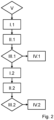
- Fig. 2 shows a flow chart of a method for detecting a malfunction of the first parking brake valve 46 and the second parking brake valve 56 of the braking device 10 from Fig. 1 according to an embodiment of the present invention.
- the control device 16 of the braking device 10 is designed to carry out the method described below.
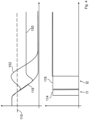
- Fig. 3 schematically illustrates brake pressure curves and control signals in the braking device 10 during the execution of the Fig. 2
- the upper half of the Figure 2 shows schematically three possible pressure curves which are present on the brake pressure output line 22 and can be measured by the pressure sensor 76. The time is plotted along the horizontal axis and the measured pressure along the vertical axis.
- the lower half of the Fig. 2 shows schematically the control signals 114 and 116 of the first parking brake valve 46 and the second parking brake valve 56, with which the parking brake valves 46 and 56 are controlled by means of the control device 16.
- a first step 1.1 of the Fig. 2 the control device 16 activates the first parking brake valve 46 of the Fig. 1 illustrated braking device 10, as indicated by the control signal 114 of the first parking brake valve 46 in the lower diagram of Fig. 3
- the activation 1.1 of the valve 46 initiates the opening of the valve. If the parking brake valve 46 is not activated, it is closed. During the time period t1 in Fig. 3 the parking brake valve 46 is therefore activated, then the parking brake valve 46 is no longer activated.
- the first parking brake valve 46 is energized and opened by the activation 1.1, which leads to a drop in pressure in the brake pressure output line 22, provided that there is no malfunction in the first parking brake valve 46. If the first parking brake valve 46 functions as intended, a brake pressure curve 118 is established as intended, which in Fig. 3 shown.
- a first faulty brake pressure curve 120 is shown, which represents a possible brake pressure curve in the event of a malfunction of the first parking brake valve 46.
- the parking brake valve 46 is controlled in the same way in both cases.
- the brake control pressure initially remains in the Essentially unchanged and does not decrease, as is the case with the error-free brake pressure curve 118.
- the underlying malfunction can be, for example, a defective valve, but also a defective first valve electronics 44 or first brake control line 48. Due to the malfunction, no pressure is passed via the shuttle valve 60 to the first relay valve 24, as a result of which the brake pressure does not decrease and the brake 14 is not released.
- a step of determining 11.1 a state variable is carried out, the state variable being the pressure along the brake pressure output line 22, which in the present embodiment is determined via the pressure sensor 76. If there is no malfunction of the parking brake valve 46, the pressure falls below the value specified in Fig. 3 shown reference value 110. Consequently, in a subsequent step III.1, the determined state variable, i.e. the pressure in the brake pressure output line 22, is compared with the reference value 110. If the comparison III.1 leads to the result that the pressure determined in step 11.1 is above the reference value 110, a malfunction of the first valve is detected by the control device 16 in a subsequent step IV.1.
- control device 16 sends a signal to the driver in step IV.1 and informs him of the detected malfunction of the parking brake valve 46. If the determined pressure is below the reference value 110, it is determined in step IV.1 that the parking brake valve 46 is functioning as intended.
- step IV.1 after a first time t1, starting from the start of activation 1.1 of the first valve 46, a further activation I.2 of the second valve is carried out.
- the first valve 46 is no longer activated, which is why it is closed.
- the control device 16 opens the second parking brake valve 56 in accordance with the above description for the first parking brake valve 46, whereby the pressure on the brake pressure output line 22 continues to drop along the fault-free brake pressure curve 118 as described above, if there is no malfunction in the second parking brake valve 56.
- the pressure drops along the curve 120 if the second parking brake valve 56 is fault-free, as in Fig. 3 If, however, only the second parking brake valve 56 is faulty, the pressure rises from the curve 118 to now correspond to the second faulty brake pressure curve 122 in Fig. 3
- the second faulty brake pressure curve 122 initially follows the fault-free brake pressure curve 118 until it increases relative to it as described above.
- a step of further determining II.2 a further state variable is therefore now carried out.
- the further state variable is the pressure along the brake pressure output line 22, which is also determined via the pressure sensor 76. If there is no malfunction of the second parking brake valve 56, the pressure remains or falls below the reference value 110 during the second waiting time 127. This corresponds to the error-free brake pressure curve 118 or the brake pressure curve 120. Otherwise, the pressure now rises above the reference value 110 according to the curve 122. Therefore, a step of further comparing III.2 the determined state variable is carried out, in which the determined pressure is compared with the reference value 110.
- the first parking brake valve 46 is activated again, whereby both parking brake valves 46 and 56 are opened and a parking brake function is released.
- a test step V is carried out to determine whether the service brake module 70 is operated above a limit value. In the present embodiment, it is checked whether the service brake module 70 applies a pressure above a limit value to the brake pressure output line 22. Such a test by the service brake module 70 applied pressure could distort the detection IV of a malfunction of the first parking brake valve 46 or the second parking brake valve 56. Accordingly, the method of the present embodiment is only carried out if the service brake module 70 is not operated above the limit value. As can be seen from Fig.
- the pressure curve in the brake pressure output line 22 can be influenced by actuating the service brake module 70, as shown by curves 150 and 152.
- the deviations of curves 150 and 152 from pressure curve 118 are caused here by actuating the service brake module 70.
- Fig. 4 otherwise according to the above statements to Fig. 3 built.
- the parking brake module 40 has a control pressure sensor line 140 and a control pressure sensor 142, which in Fig. 1 are shown in dashed lines.
- the control pressure sensor 142 measures the control pressure on the control pressure line 62 via the control pressure sensor line 140. This allows a pressure to be determined which is not influenced by the service brake module 70 or the redundancy module 90. This means that malfunctions in these components can be avoided when detecting a malfunction of the first parking brake valve 46 or the second parking brake valve 56. Otherwise, this alternative embodiment corresponds to the one described at the beginning in connection with Fig. 1 described embodiment.
- the method can be Fig. 2 can also be carried out in this alternative embodiment in accordance with the above statements.
- the parking brake module 40 has a first parking brake sensor line 130, a first parking brake pressure sensor 132, a second parking brake sensor line 134 and a second parking brake pressure sensor 136. These are shown in Fig. 1 shown in dashed lines.
- the first parking brake pressure sensor 132 measures the pressure passed through the first parking brake valve 46 via the first parking brake sensor line 130.
- the second parking brake pressure sensor 136 measures the pressure passed through the second parking brake valve 56 via the second parking brake sensor line 134. This allows two separate pressures to be determined before they are combined via the shuttle valve 60. By comparing the two determined pressures with a reference value 110, a malfunction of the first Parking brake valve 46 or the second parking brake valve 56.
Landscapes
- Engineering & Computer Science (AREA)
- Transportation (AREA)
- Mechanical Engineering (AREA)
- Valves And Accessory Devices For Braking Systems (AREA)
Applications Claiming Priority (1)
| Application Number | Priority Date | Filing Date | Title |
|---|---|---|---|
| DE102023206706.4A DE102023206706A1 (de) | 2023-07-14 | 2023-07-14 | Verfahren zum Detektieren einer Fehlfunktion eines Ventils |
Publications (1)
| Publication Number | Publication Date |
|---|---|
| EP4491468A1 true EP4491468A1 (fr) | 2025-01-15 |
Family
ID=91582133
Family Applications (1)
| Application Number | Title | Priority Date | Filing Date |
|---|---|---|---|
| EP24182472.1A Pending EP4491468A1 (fr) | 2023-07-14 | 2024-06-17 | Procédé de détection d'un dysfonctionnement d'une soupape |
Country Status (3)
| Country | Link |
|---|---|
| US (1) | US20250018919A1 (fr) |
| EP (1) | EP4491468A1 (fr) |
| DE (1) | DE102023206706A1 (fr) |
Citations (6)
| Publication number | Priority date | Publication date | Assignee | Title |
|---|---|---|---|---|
| DE102011106522B3 (de) * | 2011-06-15 | 2012-10-25 | Voith Patent Gmbh | Steuerluftsystem und Verfahren zur Steuerung eines hydrodynamischen Retarders mittels einem solchen System |
| EP2119610B1 (fr) * | 2008-05-09 | 2014-12-03 | KNORR-BREMSE Systeme für Nutzfahrzeuge GmbH | Dispositif et procédé de fonctionnement et de surveillance d'une soupape magnétique d'un frein de stationnement électrique |
| DE102019100869A1 (de) | 2019-01-15 | 2020-07-16 | Wabco Gmbh | Ventilanordnung eines hydraulisch gebremsten Zugfahrzeugs zur Steuerung des Bremsdruckes eines pneumatisch gebremsten Anhängerfahrzeugs |
| DE102019134843A1 (de) * | 2019-12-18 | 2021-06-24 | Voith Patent Gmbh | Steuerluftsystem für einen hydrodynamischen Retarder |
| DE102020122918A1 (de) * | 2020-09-02 | 2022-03-03 | Linde Material Handling Gmbh | Mobile Arbeitsmaschine, insbesondere Flurförderzeug |
| EP3787943B1 (fr) * | 2018-05-03 | 2022-06-22 | Volvo Truck Corporation | Unité de freinage redondante pour un système de freinage et système l'utilisant |
Family Cites Families (2)
| Publication number | Priority date | Publication date | Assignee | Title |
|---|---|---|---|---|
| DE10142790B4 (de) * | 2001-08-31 | 2007-01-18 | Winkle, Günther, Dipl.-Ing.(TU) | Bremsdiagnose für Schienen- und Straßenfahrzeuge |
| US20150084402A1 (en) * | 2013-09-26 | 2015-03-26 | Bendix Commercial Vehicle Systems Llc | Automatic traction relay valve diagnostic using pressure transducer feedback |
-
2023
- 2023-07-14 DE DE102023206706.4A patent/DE102023206706A1/de active Pending
-
2024
- 2024-06-17 EP EP24182472.1A patent/EP4491468A1/fr active Pending
- 2024-07-11 US US18/769,938 patent/US20250018919A1/en active Pending
Patent Citations (6)
| Publication number | Priority date | Publication date | Assignee | Title |
|---|---|---|---|---|
| EP2119610B1 (fr) * | 2008-05-09 | 2014-12-03 | KNORR-BREMSE Systeme für Nutzfahrzeuge GmbH | Dispositif et procédé de fonctionnement et de surveillance d'une soupape magnétique d'un frein de stationnement électrique |
| DE102011106522B3 (de) * | 2011-06-15 | 2012-10-25 | Voith Patent Gmbh | Steuerluftsystem und Verfahren zur Steuerung eines hydrodynamischen Retarders mittels einem solchen System |
| EP3787943B1 (fr) * | 2018-05-03 | 2022-06-22 | Volvo Truck Corporation | Unité de freinage redondante pour un système de freinage et système l'utilisant |
| DE102019100869A1 (de) | 2019-01-15 | 2020-07-16 | Wabco Gmbh | Ventilanordnung eines hydraulisch gebremsten Zugfahrzeugs zur Steuerung des Bremsdruckes eines pneumatisch gebremsten Anhängerfahrzeugs |
| DE102019134843A1 (de) * | 2019-12-18 | 2021-06-24 | Voith Patent Gmbh | Steuerluftsystem für einen hydrodynamischen Retarder |
| DE102020122918A1 (de) * | 2020-09-02 | 2022-03-03 | Linde Material Handling Gmbh | Mobile Arbeitsmaschine, insbesondere Flurförderzeug |
Also Published As
| Publication number | Publication date |
|---|---|
| DE102023206706A1 (de) | 2025-01-16 |
| US20250018919A1 (en) | 2025-01-16 |
Similar Documents
| Publication | Publication Date | Title |
|---|---|---|
| EP3600993B1 (fr) | Système de freinage pouvant être commandé de manière électronique ainsi que procédé servant à commander le système de freinage pouvant être commandé de manière électronique | |
| EP2288523B2 (fr) | Dispositif de surveillance de systèmes véhiculaires | |
| EP4396049B1 (fr) | Procédé de fonctionnement d'un système de freinage électropneumatique, unité de soupape à sécurité intégrée, système de freinage électropneumatique et véhicule | |
| EP3755589B1 (fr) | Équipement électropneumatique d'un véhicule | |
| EP3678909B1 (fr) | Dispositif electropneumatique de commande de frein de stationnement et systeme de freinage de vehicule | |
| EP2298616B2 (fr) | Appareil de commande et procédé de test d'un dispositif de soupape d'un frein de stationnement électrique | |
| EP3650292B1 (fr) | Procédé de vérification fonctionnelle d'un système de freinage électronique actionné par fluide sous pression d'un véhicule | |
| EP2915710B1 (fr) | Dispositif de freinage de service d'un véhicule avec cycle d'essai pour soupapes | |
| EP2108553B1 (fr) | Frein de stationnement doté d'une fonction test et procédé d'exécution d'une fonction test | |
| EP4247676B1 (fr) | Unité de clapet à sécurité intégrée, système de freinage pneumatique à commande électronique, véhicule, et procédé | |
| DE602005001545T2 (de) | Bremsvorrichtung eines Fahrzeugs | |
| DE102008027731B4 (de) | Elektrische Feststellbremse mit Einfallsperre und Verfahren zum Betreiben einer elektrischen Feststellbremse mit Einfallsperre | |
| EP0478953B1 (fr) | Installation de freinage électro-pneumatique | |
| DE19706982A1 (de) | Bremsanlage zur Steuerung der Bremsung eines Anhängerfahrzeuges | |
| EP0535392B1 (fr) | Procédé pour diagnostiquer une installation de freinage à fluide sous pression à commande électronique d'un véhicule | |
| EP4370391A1 (fr) | Procédé de contrôle du fonctionnement d'un système de freinage électronique à fluide sous pression d'un véhicule | |
| DE102011078890A1 (de) | Überwachungsvorrichtung für zumindest eine Untereinheit eines hydraulischen Bremssystems und Verfahren zum Untersuchen einer Funktionsfähigkeit zumindest einer Untereinheit eines hydraulischen Bremssystems | |
| EP1366964B2 (fr) | Système de freinage de stationnement pour véhicules et procédé pour faire fonctionner | |
| EP1312524B1 (fr) | Méthode d'opération d'une système de freinage électriquement contrôlée | |
| DE10053334B4 (de) | Verfahren und Vorrichtung zur Steuerung eines Stellelements in einem Fahrzeug | |
| EP4491468A1 (fr) | Procédé de détection d'un dysfonctionnement d'une soupape | |
| WO2019048261A1 (fr) | Dispositif de freinage et procédé pour faire fonctionner un dispositif de freinage | |
| DE102017211608A1 (de) | Verfahren zum Betreiben einer Schalteinrichtung eines Getriebes | |
| DE102022211503B4 (de) | Überprüfung eines Ist-Drucksensors eines Kraftfahrzeug-Bremssystems | |
| WO2026052421A1 (fr) | Procédé de test fonctionnel d'une électrovanne dans un système de frein |
Legal Events
| Date | Code | Title | Description |
|---|---|---|---|
| PUAI | Public reference made under article 153(3) epc to a published international application that has entered the european phase |
Free format text: ORIGINAL CODE: 0009012 |
|
| STAA | Information on the status of an ep patent application or granted ep patent |
Free format text: STATUS: THE APPLICATION HAS BEEN PUBLISHED |
|
| AK | Designated contracting states |
Kind code of ref document: A1 Designated state(s): AL AT BE BG CH CY CZ DE DK EE ES FI FR GB GR HR HU IE IS IT LI LT LU LV MC ME MK MT NL NO PL PT RO RS SE SI SK SM TR |
|
| STAA | Information on the status of an ep patent application or granted ep patent |
Free format text: STATUS: REQUEST FOR EXAMINATION WAS MADE |
|
| 17P | Request for examination filed |
Effective date: 20250715 |