EP4491510A1 - Einzelklappenantriebssystem für dezentralisierte klappenarchitekturen - Google Patents
Einzelklappenantriebssystem für dezentralisierte klappenarchitekturen Download PDFInfo
- Publication number
- EP4491510A1 EP4491510A1 EP23185293.0A EP23185293A EP4491510A1 EP 4491510 A1 EP4491510 A1 EP 4491510A1 EP 23185293 A EP23185293 A EP 23185293A EP 4491510 A1 EP4491510 A1 EP 4491510A1
- Authority
- EP
- European Patent Office
- Prior art keywords
- drive
- actuators
- flow body
- movable flow
- station
- Prior art date
- Legal status (The legal status is an assumption and is not a legal conclusion. Google has not performed a legal analysis and makes no representation as to the accuracy of the status listed.)
- Pending
Links
Images




Classifications
-
- B—PERFORMING OPERATIONS; TRANSPORTING
- B64—AIRCRAFT; AVIATION; COSMONAUTICS
- B64C—AEROPLANES; HELICOPTERS
- B64C9/00—Adjustable control surfaces or members, e.g. rudders
- B64C9/14—Adjustable control surfaces or members, e.g. rudders forming slots
- B64C9/16—Adjustable control surfaces or members, e.g. rudders forming slots at the rear of the wing
- B64C9/18—Adjustable control surfaces or members, e.g. rudders forming slots at the rear of the wing by single flaps
-
- B—PERFORMING OPERATIONS; TRANSPORTING
- B64—AIRCRAFT; AVIATION; COSMONAUTICS
- B64C—AEROPLANES; HELICOPTERS
- B64C13/00—Control systems or transmitting systems for actuating flying-control surfaces, lift-increasing flaps, air brakes, or spoilers
- B64C13/24—Transmitting means
- B64C13/38—Transmitting means with power amplification
- B64C13/50—Transmitting means with power amplification using electrical energy
-
- B—PERFORMING OPERATIONS; TRANSPORTING
- B64—AIRCRAFT; AVIATION; COSMONAUTICS
- B64C—AEROPLANES; HELICOPTERS
- B64C11/00—Propellers, e.g. of ducted type; Features common to propellers and rotors for rotorcraft
- B64C11/30—Blade pitch-changing mechanisms
- B64C11/44—Blade pitch-changing mechanisms electric
-
- B—PERFORMING OPERATIONS; TRANSPORTING
- B64—AIRCRAFT; AVIATION; COSMONAUTICS
- B64C—AEROPLANES; HELICOPTERS
- B64C13/00—Control systems or transmitting systems for actuating flying-control surfaces, lift-increasing flaps, air brakes, or spoilers
- B64C13/24—Transmitting means
- B64C13/26—Transmitting means without power amplification or where power amplification is irrelevant
- B64C13/28—Transmitting means without power amplification or where power amplification is irrelevant mechanical
- B64C13/30—Transmitting means without power amplification or where power amplification is irrelevant mechanical using cable, chain, or rod mechanisms
-
- B—PERFORMING OPERATIONS; TRANSPORTING
- B64—AIRCRAFT; AVIATION; COSMONAUTICS
- B64C—AEROPLANES; HELICOPTERS
- B64C13/00—Control systems or transmitting systems for actuating flying-control surfaces, lift-increasing flaps, air brakes, or spoilers
- B64C13/24—Transmitting means
- B64C13/26—Transmitting means without power amplification or where power amplification is irrelevant
- B64C13/28—Transmitting means without power amplification or where power amplification is irrelevant mechanical
- B64C13/34—Transmitting means without power amplification or where power amplification is irrelevant mechanical using toothed gearing
-
- B—PERFORMING OPERATIONS; TRANSPORTING
- B64—AIRCRAFT; AVIATION; COSMONAUTICS
- B64C—AEROPLANES; HELICOPTERS
- B64C9/00—Adjustable control surfaces or members, e.g. rudders
- B64C9/14—Adjustable control surfaces or members, e.g. rudders forming slots
- B64C9/22—Adjustable control surfaces or members, e.g. rudders forming slots at the front of the wing
- B64C9/24—Adjustable control surfaces or members, e.g. rudders forming slots at the front of the wing by single flap
-
- B—PERFORMING OPERATIONS; TRANSPORTING
- B64—AIRCRAFT; AVIATION; COSMONAUTICS
- B64D—EQUIPMENT FOR FITTING IN OR TO AIRCRAFT; FLIGHT SUITS; PARACHUTES; ARRANGEMENT OR MOUNTING OF POWER PLANTS OR PROPULSION TRANSMISSIONS IN AIRCRAFT
- B64D45/00—Aircraft indicators or protectors not otherwise provided for
- B64D45/0005—Devices specially adapted to indicate the position of a movable element of the aircraft, e.g. landing gear
-
- B—PERFORMING OPERATIONS; TRANSPORTING
- B64—AIRCRAFT; AVIATION; COSMONAUTICS
- B64C—AEROPLANES; HELICOPTERS
- B64C9/00—Adjustable control surfaces or members, e.g. rudders
- B64C9/14—Adjustable control surfaces or members, e.g. rudders forming slots
- B64C2009/143—Adjustable control surfaces or members, e.g. rudders forming slots comprising independently adjustable elements for closing or opening the slot between the main wing and leading or trailing edge flaps
Definitions
- the invention generally relates to movable flap systems.
- the invention relates to a drive assembly for driving a movable flow body of an aircraft, a drive system comprising a plurality of drive assemblies, a high lift/flap system, an aircraft wing and a method for controlling a drive system.
- Movable flap systems are typically used in an aircraft to be able to switch between a takeoff or landing configuration with comparatively lower speed and a cruise configuration with higher speed.
- the flaps which are movable flow bodies at the trailing edge of an aircraft, can be set to different positions for certain situations. Since the aerodynamics of an aircraft are basically designed for cruising flight, landing flaps allow the aerodynamics to be adapted to the requirements for special flight manoeuvres such as take-off and landing. By extending and retracting them, the surface area and the profile camber of the wing are artificially enlarged and thus provide more lift. Consequently, the aircraft is already airworthy at very low speeds.
- Flap actuation systems can be driven centrally, wherein mechanical transmission shafts are routed along the wing and drive the flaps by a central power drive unit (PDU).
- PDU central power drive unit
- This mechanical connection synchronizes the flaps between left-hand and right-hand wing and between inboard and outboard flap on both wings.
- Centrally driven flap actuation systems guarantee symmetry and uniform movement of all flap surfaces.
- disadvantages such as the difficult physical integration of a long transmission shaft with various supporting bearing and routing direction changing gear boxes, which mandates a complex and heavy system.
- it uses up valuable installation space behind the wing rear spar which could be used for other purposes.
- DE 103 13 728 B4 discloses an airplane high lift surface drive system, wherein the flap system is centrally monitored and wherein the front and rear flaps are mechanically coupled to drives integrated in the wings.
- a drive assembly for driving a movable flow body of an aircraft.
- the drive assembly comprises a power drive unit (PDU) which includes a power-off brake (PoB), and a flight control computer (FCC) which is configured to control the PDU.
- the drive assembly further comprises two flex shafts, a first flex shaft connecting the PDU to an inboard drive station, and a second flex shaft connecting the inboard drive station to an outboard drive station.
- the drive assembly further comprises two actuators, a first actuator being connected to the inboard drive station and a second actuator being connected to the outboard drive station.
- the first and the second actuators are couplable with the movable flow body, which is for example a landing flap of an aircraft, and the second actuator of the drive assembly includes a position feedback sensor, which for example is a redundant position feedback sensor, configured to send a position feedback signal to the FCC.
- a position feedback sensor which for example is a redundant position feedback sensor, configured to send a position feedback signal to the FCC.
- the inventive drive assembly may be seen as an approach to provide an improved architecture of a single flap drive system and in particular, of a decentralized flap drive system.
- the architecture has been simplified in that the drive assembly comprises only one sensor and one brake; there is neither a differential gear nor a redundant motor and the assembly may not require a load sensor. All elements are arranged in series such that the PDU is located at the side of the inboard actuator. This arrangement is particularly advantageous in that inboard of the actuators there is usually more installation space available and disconnect failures can be easily detected.
- the new simplistic architecture leads to weight and cost savings and enhances the power efficiency of the drive unit.
- a more detailed control and monitoring philosophy which is explained further below, in connection with this new architecture is unique for a decentralized system.
- the inventive drive assembly is controlled by a flight control computer (FCC), which for example is a redundant flight control computer, which can monitor the position of a movable flow body using the position sensor and can send commands to a motor control electronics (MCE) of the power drive unit (PDU) of the drive assembly.
- FCC flight control computer
- MCE motor control electronics
- a movable flow body of an aircraft can be a flap, an elevator, a rudder, an aileron, a spoiler or a slat or any other movable body which comes into contact with the air flow.
- it refers here to a landing flap.
- the PDU may be seen as a core element of the drive assembly. It can drive and move the movable flow body, for example a trailing edge flap of an aircraft, to an extended or extracted position relative to the wing structure. It comprises a power-off brake, which is always engaged when the system stands still. The reason is that if the system is not operating vibrations could drive back the actuators.
- the PDU of the drive assembly can comprise: one motor which can be a single electric motor, a gear in the form of a motor spur gear, and motor control electronics (MCE) which control the speed and direction of the motor.
- the MCE may also comprise a database containing pre-programmed values, for example speed values. A speed loop inside the MCE may be in place, which uses the internal motor speed signal. The specific motor characteristics may dictate the time it needs to accelerate and decelerate the system to the desired speed.
- a flexible shaft also referred to as a 'flex shaft', is a device for transmitting rotary motion between two objects which are not fixed relative to one another. It consists of a rotating wire rope or coil which is flexible but has some torsional stiffness. It may or may not have a covering, which also bends but does not rotate. Flex shafts are well known in the art. In the present inventive assembly the flex shafts connect the PDU with an inboard drive station and then the inboard drive station to an outboard drive station in order to transmit a uniform movement by the motor of the PDU to the actuators.
- actuators move the movable flow body into an extended or retracted configuration with respect to the wing structure.
- an actuator is a part of a device or machine that helps it to achieve physical movements by converting energy, for example electrical or hydraulic energy, into mechanical force. Simply put, it is the component in any machine that enables movement.
- actuators can be classified as linear actuators or rotary actuators, wherein linear actuators provide mechanical forces in a straight line, i.e. they only have a push and pull motion.
- different types of linear actuators can be used, which may, for example, not need to have incorporated a no-back device because the screws are non-backdrivable under normal conditions.
- the second actuator which is connected to the outboard drive station includes a position feedback sensor.
- position sensors for example angular, rotary, or linear, which sensors utilize various technologies to sense position.
- the sensor is configured to detect the current position of the movable flow body and is thus capable to detect longitudinal movement of, for example, the flaps lever.
- the position feedback sensor is configured to send a position feedback signal to the FCC and may send a signal via dual channel for two flight control computers, FCC1 and FCC2.
- a voltage reference for the position feedback sensor may be necessary and may be incorporated within the sensor.
- the first and second actuators are acme screw actuators, respectively.
- Acme screws use trapezoidal threads to roll onto the lead screw. As the shaft rotates and the rotary motor turns, the threads push the shaft nut forward or backward depending on the direction of the rotating motion. This transfers the circular force of the motor into linear motion on the shaft. Due to the low efficiency the acme screw actuators are self-locking and do not necessarily require a separate braking system to be installed. That is, no specific no-back device is to be incorporated.
- At least one separate gearbox is attached to the input of the actuators.
- gearbox is a mechanical component used to change the speed and increase the motor's torque.
- the gearbox(es) may be attached to the actuator's input(s) and may be of use in setting an exact speed for the actuators which move the movable flow body.
- a load sensor is integrated on the drive station of at least one actuator.
- a load sensor is an electronic device that converts tension and compression forces into a corresponding electrical signal.
- the two simplest load sensor designs are the hydraulic load sensor and the pneumatic load sensor.
- the hydraulic sensor uses liquid and the pneumatic uses gas. When a tension or compression force is applied, the liquid or gas will expand or contract, generating an electrical signal that is directly proportional to the force applied.
- load sensors also referred to as force sensors
- the sensor is ideally positioned in such a way that the entire force flows through the sensor and the force sensor is directly in the force flow.
- an optional sensible position is on the drive station of an actuator.
- the PDU is positioned inboard of the actuators.
- a drive system comprising a plurality of drive assemblies, wherein the drive assemblies are independent from each other, such that individual flow bodies can be moved independently from each other.
- the system comprises individually driven flaps and may comprise flap pairs, the movement of which is controlled by a redundant flight control computer, for example FCC1 and FCC2.
- the system may typically further include a power supply, a circuit breaker and a communication bus.
- Each flap panel corresponds to one drive assembly, as explained above, and consequently is driven by an individual PDU.
- Each PDU gets its own command which may depend on the individual position of the flap.
- the flaps may be retracted and extended individually and with different speeds at the same time.
- the system may be a so-called Variable Shape Trailing Edge (VSTE) system, wherein flap pairs, for example 3 flap pairs, may have different flap angles for each setting. For example, in a landing setting: Flap pair 1: 35deg, Flap pair 2: 30deg, and Flap pair 3: 20deg. All flap pairs may be movable in the same speed and may also reach the intended position at different times.
- VSTE Variable Shape Trailing Edge
- the drive system can be modified for a commercial aircraft application, where, inter alia, the safety requirements are also higher. For example, the availability of the drive function needs to be higher and certain failure cases such as flap attachment disconnect and screw rupture may have to be considered.
- each assembly of the plurality of drive assemblies of the system further comprises a second electric motor, a torque summing gear and at least one load sensor on a drive station actuator.
- the PDU has been made redundant and more effective by incorporating a second electric motor and a torque summing gear.
- the other can still drive the flap, although the total power is halved.
- At least one load sensor is also included to increase safety. Depending on the actuator loads it may be recommended to use one sensor on each drive station. As mentioned above, this can be used to detect a flap attachment disconnect.
- each assembly of the plurality of drive assemblies of the system further comprises a brake located downstream after the torque summing gear and between the inboard and outboard drive station actuators, wherein the brake is designed as a constant friction brake.
- the actuators of the drive assemblies are ball screw actuators or geared rotational actuators which further include a no-back device.
- a ball screw actuator acts as a precision screw that is able to accommodate heavy loads.
- Geared Rotational Actuators are mechanically operable devices widely used in the aerospace industry so that controlled motion can be provided to secondary flight control surfaces. This variant has a better power-efficiency compared to a system with acme screws.
- the functionality of the no-back device may need to be monitored using a load sensor.
- a high lift or flap system comprising at least one movable flow body, wherein the at least one movable flow body is couplable to at least one drive assembly, or wherein the at least one movable flow body is couplable to at least one drive system, as described above.
- an aircraft wing which comprises at least one drive system or at least one drive assembly as described herein.
- an aircraft comprising the drive system as described herein is provided.
- each drive assembly gets individual commands from the FCC to its PDU depending on the individual position of the movable flow body which is detected by the position sensor. It follows that each flap may be driven individually.
- the method further comprises the monitoring of failure cases.
- Failure cases of a drive assembly or drive system for driving one or more movable flow bodies of an aircraft are monitored by use of a single position sensor, wherein the following scenarios can be detected: a shaft rupture or jam can be detected if the position sensor detects no movement but a drive command; a powered runaway of a PDU can be detected by calculating a speed of the drive assembly with the derivative of the position sensor signal; an uncommanded movement can be detected if the position sensor detects no drive command but a movement.
- the method further comprises detecting a flap attachment disconnect failure of an aircraft using at least one load sensor introduced at a drive station actuator of a drive system according to the example above.
- Fig. 1 shows a drive assembly 1 for driving a movable flow body 2 of an aircraft.
- the movable flow body 2 which is for example a landing flap, is coupled to acme screw actuators 9, 10.
- the acme screw actuators 9, 10 are each coupled to drive stations 6, 8, wherein the first acme screw actuator 9 is coupled to the inboard drive station 6 and the second acme screw actuator 10 is coupled to the outboard drive station 8.
- a power drive unit (PDU) 3 is positioned in series and inboard of the acme screw actuators 9, 10. The PDU 3 is connected to the inboard drive station 6 with a flex shaft 5, and the inboard drive station 6 is connected to the outboard drive station 8 with a flex shaft 7.
- the PDU 3 contains, among other things such as the motor spur gear, the motor and motor control electronics (MCE) (not shown), a power-off brake (PoB) 4.
- a position feedback sensor 11 is located at the outboard actuator 10, for example at the outboard drive station 8.
- the position feedback sensor 11 gives a position feedback signal 17 to the Flight Control Computer (FCC) (not shown), wherein there is further provided a voltage reference 18 for the position feedback sensor 11.
- the PDU 3 receives 28 VDC power supply 16.
- the FCC sends an Enable Signal 13 to the PDU 3, which enables the PDU 3 to perform an operation.
- the PDU 3 sends a Power Avail Signal 14 to the FCC, indicating that the PDU is powered.
- a RS485 databus 15 is provided for receiving commands from the FCC and to provide status info to the FCC.
- load sensors 12a, 12b are integrated on the drive stations 6, 8 of the acme screw actuators 9, 10 in order to detect a flap attachment disconnect.
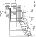
- Fig. 2 shows a schematic diagram of a drive system comprising a plurality of drive assemblies 1 as described above.
- the system is called a Variable Shape Trailing Edge System (VSTE).
- VSTE Variable Shape Trailing Edge System
- the schematic shows the general architecture including power supply 33a, circuit breaker 33 and communication bus 33b.
- Three flap pairs are shown which are controlled by a redundant flight computer FCC1, FCC2 19,20, and which are driven individually. That is, the outermost flaps VSTE3LH and VSTE3RH 27, 32 of each wing form a pair, the middle flaps VSTE2LH and VSTE2RH 28, 31 of each wing form a pair, and the innermost flaps VSTE1LH and VSTE1RH 29, 30 of each wing form a pair.
- each flap 27, 28, 29, 30, 31, 32 is driven by its own PDU 21, 22, 23, 24, 25, 26 which is individually controlled by the redundant Flight Control Computer FCC1, FCC2.
- the Flight Control Computer FCC1 19 is coupled to three relays (37-39) and also the Flight Control Computer FCC2 20 is coupled to three relays (34-36).
- Figs. 2a and 2b show the right and the left side of Fig. 2 slightly enlarged.
- Fig. 3 shows a schematic illustration of a modified VSTE Drive System for Commercial Aircraft Application.
- the movable flow body 2 is a landing flap of an aircraft, which is coupled to two actuators 40.
- the PDU is made redundant, i.e. two electric motors 43 with two motor control electronics (MCE) 44 and a torque summing gear 45 are provided.
- MCE motor control electronics
- a brake 46 is located downstream on the flex shaft 41 after the torque summing gear 45 and between the inboard and outboard drive station actuator 40. This ensures that a shaft rupture would not lead to a movement of the system although the brake is engaged.
- a no-back device (not shown) is involved on ball screw or geared rotational actuators 40. This variant has a better power-efficiency.
- the no-back device is monitored using the load sensor(s) 42.
- Fig. 4 is a diagram showing a drive sequence for moving a flow body 2 of an aircraft.
- the speed loop which is saved in the database of the MCE starts with a high speed or low speed command 50, whereupon the PDU receives the command 51 to open the power-off brake (PoB) from the FCC.
- PoB power-off brake
- the PDU will receive the command 56 to return to low speed and a predetermined time will be spent to decelerate to the low speed 57. Before the speed is reduced to zero, the PDU receives the command 58 to close the power-off brake (PoB).
- PoB power-off brake
Landscapes
- Engineering & Computer Science (AREA)
- Aviation & Aerospace Engineering (AREA)
- Mechanical Engineering (AREA)
- Automation & Control Theory (AREA)
- Transmission Devices (AREA)
- Retarders (AREA)
Priority Applications (2)
| Application Number | Priority Date | Filing Date | Title |
|---|---|---|---|
| EP23185293.0A EP4491510A1 (de) | 2023-07-13 | 2023-07-13 | Einzelklappenantriebssystem für dezentralisierte klappenarchitekturen |
| US18/768,690 US20250019067A1 (en) | 2023-07-13 | 2024-07-10 | Single Flap Drive System For Decentralized Flap Architectures |
Applications Claiming Priority (1)
| Application Number | Priority Date | Filing Date | Title |
|---|---|---|---|
| EP23185293.0A EP4491510A1 (de) | 2023-07-13 | 2023-07-13 | Einzelklappenantriebssystem für dezentralisierte klappenarchitekturen |
Publications (1)
| Publication Number | Publication Date |
|---|---|
| EP4491510A1 true EP4491510A1 (de) | 2025-01-15 |
Family
ID=87280524
Family Applications (1)
| Application Number | Title | Priority Date | Filing Date |
|---|---|---|---|
| EP23185293.0A Pending EP4491510A1 (de) | 2023-07-13 | 2023-07-13 | Einzelklappenantriebssystem für dezentralisierte klappenarchitekturen |
Country Status (2)
| Country | Link |
|---|---|
| US (1) | US20250019067A1 (de) |
| EP (1) | EP4491510A1 (de) |
Citations (6)
| Publication number | Priority date | Publication date | Assignee | Title |
|---|---|---|---|---|
| US20080229851A1 (en) * | 2007-03-20 | 2008-09-25 | Goodrich Actuation Systems Limited | Actuator Arrangement |
| DE10313728B4 (de) | 2003-03-27 | 2011-07-21 | Airbus Operations GmbH, 21129 | Klappensystem am Tragflügel eines Starrflügel-Flugzeuges |
| US20110234237A1 (en) * | 2010-03-24 | 2011-09-29 | Timothy Michael Mayer | Aircraft slat disconnect sensor |
| US20150321750A1 (en) * | 2007-05-09 | 2015-11-12 | Liebherr-Aerospace Lindenberg Gmbh | Drive system for a variable camber aircraft wing |
| US20200094945A1 (en) * | 2018-09-24 | 2020-03-26 | The Boeing Company | Distributed Linear Hydraulic High Lift Actuation System With Synchronization Members |
| EP3653493A1 (de) * | 2018-11-16 | 2020-05-20 | Bombardier Inc. | Hochauftriebsbetätigungssystem mit zentralisierter innenaktuatorensteuerung und unabhängiger aussenaktuatorensteuerung |
-
2023
- 2023-07-13 EP EP23185293.0A patent/EP4491510A1/de active Pending
-
2024
- 2024-07-10 US US18/768,690 patent/US20250019067A1/en active Pending
Patent Citations (6)
| Publication number | Priority date | Publication date | Assignee | Title |
|---|---|---|---|---|
| DE10313728B4 (de) | 2003-03-27 | 2011-07-21 | Airbus Operations GmbH, 21129 | Klappensystem am Tragflügel eines Starrflügel-Flugzeuges |
| US20080229851A1 (en) * | 2007-03-20 | 2008-09-25 | Goodrich Actuation Systems Limited | Actuator Arrangement |
| US20150321750A1 (en) * | 2007-05-09 | 2015-11-12 | Liebherr-Aerospace Lindenberg Gmbh | Drive system for a variable camber aircraft wing |
| US20110234237A1 (en) * | 2010-03-24 | 2011-09-29 | Timothy Michael Mayer | Aircraft slat disconnect sensor |
| US20200094945A1 (en) * | 2018-09-24 | 2020-03-26 | The Boeing Company | Distributed Linear Hydraulic High Lift Actuation System With Synchronization Members |
| EP3653493A1 (de) * | 2018-11-16 | 2020-05-20 | Bombardier Inc. | Hochauftriebsbetätigungssystem mit zentralisierter innenaktuatorensteuerung und unabhängiger aussenaktuatorensteuerung |
Also Published As
| Publication number | Publication date |
|---|---|
| US20250019067A1 (en) | 2025-01-16 |
Similar Documents
| Publication | Publication Date | Title |
|---|---|---|
| US8814085B2 (en) | Fault-tolerant actuating system for adjusting flaps of an aircraft, comprising adjustment kinematics with a fixed pivot, and a method for monitoring an actuating system | |
| JP4418698B2 (ja) | 固定翼飛行機の主翼のフラップシステム | |
| US10538310B2 (en) | Near synchronous distributed hydraulic motor driven actuation system | |
| EP2851284B1 (de) | Variables Wölbklappensystem und Verfahren | |
| US20200156766A1 (en) | High-lift actuation system having independent actuation control | |
| CN111196349B (zh) | 具有集中内侧致动控制和独立外侧致动控制的高升力致动系统 | |
| US7556224B2 (en) | Distributed flight control surface actuation system | |
| US9190942B2 (en) | Near synchronous controlled induction motor drive actuation system | |
| US11174006B2 (en) | High-lift actuation system with clutch architecture | |
| CN113460288B (zh) | 用于控制飞行器的主动式方向舵脚蹬组件以及飞行器 | |
| CN111439370B (zh) | 高升力系统及襟翼控制方法 | |
| US20250019067A1 (en) | Single Flap Drive System For Decentralized Flap Architectures | |
| EP4549315B1 (de) | Fehlertolerante rotierende ema | |
| RU2622321C1 (ru) | Система рулевых поверхностей с электромеханическими приводами для управления основными летными функциями самолета | |
| EP4733188A1 (de) | Antriebsanordnung zum antreiben einer beweglichen strömungsvorrichtung eines flugzeugs | |
| EP4400419B1 (de) | Antriebsanordnung zum antreiben eines beweglichen strömungskörpers eines flugzeugs | |
| CN119527534A (zh) | 一种分布式缝翼控制系统及方法 |
Legal Events
| Date | Code | Title | Description |
|---|---|---|---|
| PUAI | Public reference made under article 153(3) epc to a published international application that has entered the european phase |
Free format text: ORIGINAL CODE: 0009012 |
|
| STAA | Information on the status of an ep patent application or granted ep patent |
Free format text: STATUS: THE APPLICATION HAS BEEN PUBLISHED |
|
| AK | Designated contracting states |
Kind code of ref document: A1 Designated state(s): AL AT BE BG CH CY CZ DE DK EE ES FI FR GB GR HR HU IE IS IT LI LT LU LV MC ME MK MT NL NO PL PT RO RS SE SI SK SM TR |
|
| STAA | Information on the status of an ep patent application or granted ep patent |
Free format text: STATUS: REQUEST FOR EXAMINATION WAS MADE |
|
| 17P | Request for examination filed |
Effective date: 20250708 |
|
| STAA | Information on the status of an ep patent application or granted ep patent |
Free format text: STATUS: EXAMINATION IS IN PROGRESS |
|
| 17Q | First examination report despatched |
Effective date: 20260401 |