EP4491519A1 - Anordnung mit einem offentürverriegelungssystem - Google Patents
Anordnung mit einem offentürverriegelungssystem Download PDFInfo
- Publication number
- EP4491519A1 EP4491519A1 EP23184804.5A EP23184804A EP4491519A1 EP 4491519 A1 EP4491519 A1 EP 4491519A1 EP 23184804 A EP23184804 A EP 23184804A EP 4491519 A1 EP4491519 A1 EP 4491519A1
- Authority
- EP
- European Patent Office
- Prior art keywords
- open
- sliding block
- assembly
- door
- cowling
- Prior art date
- Legal status (The legal status is an assumption and is not a legal conclusion. Google has not performed a legal analysis and makes no representation as to the accuracy of the status listed.)
- Pending
Links
Images



Classifications
-
- B—PERFORMING OPERATIONS; TRANSPORTING
- B64—AIRCRAFT; AVIATION; COSMONAUTICS
- B64C—AEROPLANES; HELICOPTERS
- B64C1/00—Fuselages; Constructional features common to fuselages, wings, stabilising surfaces or the like
- B64C1/14—Windows; Doors; Hatch covers or access panels; Surrounding frame structures; Canopies; Windscreens accessories therefor, e.g. pressure sensors, water deflectors, hinges, seals, handles, latches, windscreen wipers
- B64C1/1407—Doors; surrounding frames
- B64C1/1446—Inspection hatches
-
- B—PERFORMING OPERATIONS; TRANSPORTING
- B64—AIRCRAFT; AVIATION; COSMONAUTICS
- B64D—EQUIPMENT FOR FITTING IN OR TO AIRCRAFT; FLIGHT SUITS; PARACHUTES; ARRANGEMENT OR MOUNTING OF POWER PLANTS OR PROPULSION TRANSMISSIONS IN AIRCRAFT
- B64D29/00—Power-plant nacelles, fairings or cowlings
- B64D29/06—Attaching of nacelles, fairings or cowlings
-
- B—PERFORMING OPERATIONS; TRANSPORTING
- B64—AIRCRAFT; AVIATION; COSMONAUTICS
- B64D—EQUIPMENT FOR FITTING IN OR TO AIRCRAFT; FLIGHT SUITS; PARACHUTES; ARRANGEMENT OR MOUNTING OF POWER PLANTS OR PROPULSION TRANSMISSIONS IN AIRCRAFT
- B64D29/00—Power-plant nacelles, fairings or cowlings
- B64D29/08—Inspection panels for power plants
-
- E—FIXED CONSTRUCTIONS
- E05—LOCKS; KEYS; WINDOW OR DOOR FITTINGS; SAFES
- E05B—LOCKS; ACCESSORIES THEREFOR; HANDCUFFS
- E05B53/00—Operation or control of locks by mechanical transmissions, e.g. from a distance
- E05B53/003—Operation or control of locks by mechanical transmissions, e.g. from a distance flexible
- E05B53/005—Bowden
-
- E—FIXED CONSTRUCTIONS
- E05—LOCKS; KEYS; WINDOW OR DOOR FITTINGS; SAFES
- E05C—BOLTS OR FASTENING DEVICES FOR WINGS, SPECIALLY FOR DOORS OR WINDOWS
- E05C1/00—Fastening devices with bolts moving rectilinearly
- E05C1/08—Fastening devices with bolts moving rectilinearly with latching action
- E05C1/12—Fastening devices with bolts moving rectilinearly with latching action with operating handle or equivalent member moving otherwise than rigidly with the latch
- E05C1/14—Fastening devices with bolts moving rectilinearly with latching action with operating handle or equivalent member moving otherwise than rigidly with the latch the handle or member moving essentially towards or away from the plane of the wing or frame
-
- E—FIXED CONSTRUCTIONS
- E05—LOCKS; KEYS; WINDOW OR DOOR FITTINGS; SAFES
- E05C—BOLTS OR FASTENING DEVICES FOR WINGS, SPECIALLY FOR DOORS OR WINDOWS
- E05C17/00—Devices for holding wings open; Devices for limiting opening of wings or for holding wings open by a movable member extending between frame and wing; Braking devices, stops or buffers, combined therewith
- E05C17/02—Devices for holding wings open; Devices for limiting opening of wings or for holding wings open by a movable member extending between frame and wing; Braking devices, stops or buffers, combined therewith by mechanical means
- E05C17/025—Means acting between hinged edge and frame
-
- E—FIXED CONSTRUCTIONS
- E05—LOCKS; KEYS; WINDOW OR DOOR FITTINGS; SAFES
- E05F—DEVICES FOR MOVING WINGS INTO OPEN OR CLOSED POSITION; CHECKS FOR WINGS; WING FITTINGS NOT OTHERWISE PROVIDED FOR, CONCERNED WITH THE FUNCTIONING OF THE WING
- E05F3/00—Closers or openers with braking devices, e.g. checks; Construction of pneumatic or liquid braking devices
- E05F3/22—Additional arrangements for closers, e.g. for holding the wing in opened or other position
- E05F3/221—Mechanical power-locks, e.g. for holding the wing open or for free-moving zones
-
- E—FIXED CONSTRUCTIONS
- E05—LOCKS; KEYS; WINDOW OR DOOR FITTINGS; SAFES
- E05Y—INDEXING SCHEME ASSOCIATED WITH SUBCLASSES E05D AND E05F, RELATING TO CONSTRUCTION ELEMENTS, ELECTRIC CONTROL, POWER SUPPLY, POWER SIGNAL OR TRANSMISSION, USER INTERFACES, MOUNTING OR COUPLING, DETAILS, ACCESSORIES, AUXILIARY OPERATIONS NOT OTHERWISE PROVIDED FOR, APPLICATION THEREOF
- E05Y2900/00—Application of doors, windows, wings or fittings thereof
- E05Y2900/50—Application of doors, windows, wings or fittings thereof for vehicles
- E05Y2900/502—Application of doors, windows, wings or fittings thereof for vehicles for aircraft or spacecraft
Definitions
- the present invention relates to an assembly with a carrier element, a hinged door that is pivotally mounted to the carrier element and pivotable between a closed position and an open position, and an open-door locking system for locking the hinged door in the open position.
- the present invention further relates to an aircraft comprising such an assembly.
- Assemblies with carrier elements and hinged doors which are pivotally mounted to the carrier elements and pivotable between closed positions and open positions are widely used.
- such carrier elements may be formed by cowlings of aircrafts and the hinged doors may be cowling access doors which are pivotally mounted to the cowlings.
- a cowling may be used in aviation for drag reduction or engine cooling by directing airflow.
- the cowling may also cover a part of the fuselage, the engines, and/or a part of the cockpit of an aircraft.
- Cowling access doors usually provide access to the machinery of the aircraft that is hidden from the outside by the cowling, for example to enable maintenance work on the machinery.
- open holding systems that may be mounted to the cowling or to the cowling access door usually secure the cowling access door in an open position.
- Conventional open holding systems that enable the securing of the cowling access door in an open position include gas springs and/or hold open rods.
- gas springs and/or hold open rods usually extend from one extremity of the cowling access door to the remaining part of the cowling.
- gas springs and/or hold open rods often restrict and/or hinder a maintenance worker's access to the machinery.
- gas springs do not protect against unintended closing of the cowling access door and require maintenance due to the aging of gaskets, while hold open rods require a two-hands operation and take a lot of space for installation.
- open holding systems sometimes include the use of folding struts for securing a cowling access door in an open position.
- folding struts are usually not in the way of maintenance workers.
- folding struts usually also require a two-hands operation.
- the document EP 0 839 714 A1 describes a latch for a thrust reverser duct on an aircraft engine.
- the latch accomplishes work during both the closing stroke and the handle folding stroke.
- An outer handle release trigger can lock an outer handle to an inner handle to fix the relative position of the outer handle, the inner handle, an idler link, a rocker link and a secondary link. While they are in fixed position, the parts act as a closing handle unit during the closing stroke. Once the closing stroke is completed, the inner handle is locked into a fixed position with hook arm and a primary link. The outer handle release trigger can then be disengaged and the secondary link, the rocker link and the idler link work to provide mechanical advantage during the folding of the outer handle.
- the document EP 1 066 195 A1 describes a remotely actuated latch mechanism for securing a cowling to an engine pylon including a handle having a closed and an open position, which is connected to a remote latch.
- the remote latch comprises a housing, a linking mechanism mounted to the housing, and a strut connected to the linking mechanism at a first end and to a keeper at a second end.
- the handle is connected to the linking mechanism of the remote latch by a push/pull cable.
- the actuation of the handle from the closed position to the open position causes the push/pull cable to move the linking mechanism of the remote latch such that the strut moves from a closed to an open position relative to the keeper allowing the cowling of the aircraft to then be pivoted open.
- the strut and the keeper are securely engaged in both the open and closed position insuring that when the latch is remotely opened and closed that the keeper is always properly engaged and that the latch properly closes.
- the document EP 1 379 745 A2 describes a lever that is actuatable to unlatch a pawl when the lever is in an unlocked position.
- lever actuation cannot unlatch the pawl.
- An over-center device coupled to the lever can be used to position the lever in its locked and unlocked positions. The lever may be moved away from the pawl when the lever is in a locked position and is moved closer to the pawl when the lever is in an unlocked position. Alternatively, the lever is pivotable about a pivot point that remains in the same location with respect to the lever in the unlocked and locked positions thereof.
- the pawl is movable by the lever to its unlatched state after the partially or fully-actuated lever has been moved to its unlocked state.
- the document EP 4 067 235 A1 describes an open holding system for a cowling access door of a cowling, wherein the cowling access door is movable between a closed position and an open position.
- the open holding system comprises a hinge bracket, a cowling access door holder, and a remote actuator.
- the hinge bracket is adapted for pivotally attaching the cowling access door to the cowling.
- the cowling access door holder comprises an overcentering latch that is in an unclamped state when the cowling access door is in the closed position and movable from the unclamped state to an over-centered state when the cowling access door is moved from the closed position to the open position.
- the overcentering latch automatically latches in the over-centered state to prevent the cowling access door from returning to the closed position.
- a release system is coupled to the overcentering latch and adapted for transitioning the overcentering latch from the over-centered state to the unclamped state.
- the remote actuator is located spaced apart from the release system on the cowling access door and adapted for remotely actuating the release system.
- the open holding system described hereabove is comparatively heavy and requires a comparatively great mounting space. Furthermore, it is difficult to disassemble the cowling access door when using the open holding system and a respectively obtainable opening angle of the cowling access door is comparatively restricted. Moreover, other ones of the open holding systems described above lack an automatic latching feature to automatically secure an associated cowling access door in the open position during an opening operation. Some also require a two-hands operation during an opening and/or a closing operation of the cowling access door.
- an object of the present invention to provide a new cowling assembly with a cowling, a cowling access door that is pivotally mounted to the cowling and pivotable between a closed position and an open position, and a new cowling access door locking system for locking the cowling access door in the open position, which overcomes the above-described drawbacks of the prior art. More specifically, the new cowling access door locking system is provided for automatically securing the cowling access door in the open position after an opening operation and it is operable with a single hand, prevents an unintended closing during maintenance work, has an easily accessible release mechanism, a very compact design and comprises less constituent components, is easier to produce and assemble, and comparatively inexpensive to manufacture compared to state-of-the-art open holding systems. Another object of the present invention is to provide a new aircraft comprising such a new cowling assembly.
- the above-mentioned object is solved by a cowling assembly with a cowling, a cowling access door that is pivotally mounted to the cowling and pivotable between a closed position and an open position, and a cowling access door locking system for locking the cowling access door in the open position, as described below. More generally, the above-mentioned object is solved by an assembly with a carrier element, a hinged door that is pivotally mounted to the carrier element and pivotable between a closed position and an open position, and an open-door locking system for locking the hinged door in the open position, comprising the features of claim 1.
- an assembly with a carrier element, a hinged door that is pivotally mounted to the carrier element and pivotable between a closed position and an open position, and an open-door locking system for locking the hinged door in the open position is provided.
- the open-door locking system comprises a hinge bracket and an open-door locking device.
- the hinge bracket is rigidly attached to the carrier element and comprises a locking notch.
- the open-door locking device comprises a mounting bracket that is pivotally mounted to the hinge bracket, a housing that is connected to the mounting bracket and rigidly attached to the hinged door, a sliding block that is accommodated in the housing and slidable in the housing in a first direction between a normal position and an actuated position, and a slider that is accommodated in the housing and slidable in the housing in a second direction between a blocking position and a releasing position.
- the slider is coupled to the sliding block such that the slider is in the blocking position and engages the locking notch of the hinge bracket for blocking the hinged door in the open position when the sliding block is in the normal position.
- the assembly allows to lock the hinged door securely and reliably in the open position using the open-door locking system for preventing an unintended closing of the hinged door.
- the carrier element is e. g. a cowling of an aircraft and the hinged door is e. g. a cowling access door that provides access to machinery covered by the cowling, then maintenance personal may work on the machinery efficiently and securely with both hands.
- the open-door locking system is advantageously robust and easy to use, requires a comparatively small installation space, is light-weight, consists of a reduced part of constituent components with only few moving components, requires a comparatively small technical effort, and enables implementation of a greater opening angle of the hinged door. Furthermore, it is comparatively cost-efficient and may easily be installed on existing arrangements, thereby allowing an easy retrofitting thereof.
- the open-door locking system is adapted for being operated by means of a suitable remote actuator with a single hand.
- the remote actuator is preferably located at an easily accessible position on the hinged door, thereby enabling an ergonomic operation of the remote actuator and the hinged door.
- the remote actuator may be connected via a cable, e. g. a Bowden cable, with an open-door locking device of the open-door locking system.
- the open-door locking system may further be provided with an emergency mechanism that allows a two-hands operation of the open-door locking system, such as e. g. a push bar.
- an emergency mechanism that allows a two-hands operation of the open-door locking system, such as e. g. a push bar.
- such an emergency mechanism is at least usable when the remote actuator fails, e. g. if the cable is broken.
- the open-door locking system has a comparatively simple configuration and is easy to repair. Furthermore, the hinged door may easily and quickly be removed from the open-door locking system and the assembly as a whole.
- the slider comprises a blocking pin that engages the locking notch of the hinge bracket for blocking the hinged door in the open position when the slider is in the blocking position.
- the slider comprises a sliding member that slides in the sliding block when the sliding block slides in the housing in the first direction between the normal position and the actuated position.
- the slider is coupled to a transfer rod that is equipped with the sliding member.
- the sliding block comprises a wedge with a ramp, and the sliding member slides along the ramp in a third direction when the sliding block slides in the housing in the first direction.
- the third direction may be oblique to the first direction and the second direction.
- the first direction may be at least approximately perpendicular to the second direction.
- the open-door locking device further comprises a slider return spring that biases the slider into the blocking position.
- the open-door locking device further comprises a sliding block return spring that biases the sliding block into the normal position.
- the open-door locking system further comprises a remote actuator for remotely actuating the open-door locking device, wherein the remote actuator is located spaced apart from the open-door locking device on the hinged door.
- the open-door locking system may further comprise a cable, in particular a Bowden cable, that connects the remote actuator with the sliding block.
- a cable in particular a Bowden cable
- the remote actuator may comprise a pivotable thumb lever that is attached to the cable and pivotable for pulling the cable to cause sliding of the sliding block in the housing in the first direction between the normal position and the actuated position.
- the open-door locking device further comprises a push bar that is rigidly attached to the sliding block and operable for manually moving the sliding block in the housing in the first direction between the normal position and the actuated position.
- the slider is in the releasing position and disengaged from the locking notch of the hinge bracket for releasing the hinged door in the open position when the sliding block is in the actuated position.
- an aircraft may comprise the assembly described above.
- Exemplary embodiments may be used with any vehicle having a carrier element and a hinged door that is pivotally mounted to the carrier element and pivotable between a closed position and an open position.
- Examples for vehicles may include aircrafts such as airplanes, quadcopters, helicopters, and drones, land-based vehicles including cars, buses, trucks, and motorcycles, or vessels such as ships and boats, etc.
- FIG 1 shows an aircraft 100 that is illustratively embodied as a rotary-wing aircraft.
- the rotary-wing aircraft which is sometimes also referred to as rotorcraft, is exemplarily illustrated as a helicopter.
- helicopter 100 the aircraft 100 is hereinafter referred to as the "helicopter 100".
- the helicopter 100 comprises at least one rotor system 110, which may be embodied as a multi-blade rotor system, for providing lift and forward or backward thrust during operation.
- the at least one rotor system 110 comprises a plurality of rotor blades 112, 113 and may be powered by at least one engine 111.
- the plurality of rotor blades 112, 113 are mounted at an associated rotor head 114 to a rotor shaft 115, which rotates in operation of the helicopter 100 around an associated rotation axis.
- the helicopter 100 illustratively further comprises a fuselage 120 that forms an airframe of the helicopter 100.
- the fuselage 120 may be connected to a suitable landing gear and illustratively forms a cabin 123 and a rear fuselage 127.
- the rear fuselage 127 may be connected to a tail boom 130.
- the tail boom 130 may be provided with at least one counter-torque device 140 configured to provide counter-torque during operation, i. e. to counter the torque created by rotation of the plurality of rotor blades 112, 113 around the rotor shaft 115 for purposes of balancing the helicopter 100 in terms of yaw. If desired, the counter-torque device 140 may be shrouded.
- the at least one counter-torque device 140 is provided at an aft section of the tail boom 130 and may have a tail rotor 145.
- the aft section of the tail boom 130 may include a fin 150.
- the tail boom 130 may be provided with a suitable horizontal stabilizer 135.
- the helicopter 100 may comprise a carrier element 160 with at least one hinged door that is pivotally mounted to the carrier element 160 and pivotable between a closed position and an open position.
- the carrier element 160 may at least cover the at least one engine 111 of the helicopter 100.
- the carrier element 160 may further cover a transmission system of the helicopter 100, which may include a gear box, and/or a crest of the helicopter 100.
- the carrier element 160 is embodied as a cowling of the helicopter 100 and, therefore, referred to hereinafter as the "cowling 160", for simplicity and clarity.
- the cowling 160 includes a transmission cowling 170 that covers a transmission system of the helicopter 100, a crest cowling 175 that covers a crest of the helicopter 100, and an engine cowling 180 that covers the at least one engine 111 of the helicopter 100.
- the engine cowling 180 is provided with a cowling access door 185 that is pivotally mounted to the engine cowling 180 for providing access to the at least one engine 111.
- the cowling access door 185 is pivotable between a closed position and an open position.
- the transmission cowling 170 is provided with a cowling access door 177 that is pivotally mounted to the transmission cowling 170 for providing access to a transmission system.
- the crest cowling 175 may also be provided with a suitable cowling access door.
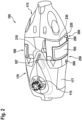
- Figure 2 shows the cowling 160 of Figure 1 , which comprises the transmission cowling 170, the crest cowling 175, and the engine cowling 180.
- the transmission cowling 170 comprises the cowling access door 177 and the engine cowling 180 comprises the cowling access door 185.
- the cowling access door 185 is pivotable around an associated hinge axis 187 at the engine cowling 180.
- At least the cowling access door 185 is pivotable between a closed position and an open position.
- the cowling access door 185 may close an opening in the engine cowling 180, thereby preventing access from outside of the engine cowling 180 to associated machinery, i. e. the at least one engine 111 of Figure 1 .
- the cowling access door 185 In the open position, the cowling access door 185, for instance, may provide access from outside of the engine cowling 180 to the associated machinery, i. e. the at least one engine 111 of Figure 1 .
- the cowling access door 185 may provide access for performing maintenance work on the associated machinery, i. e. the at least one engine 111 of Figure 1 .
- At least the cowling access door 185 is provided with an open-door locking system 200.
- the cowling access door 185 and the open-door locking system 200 form together with the engine cowling 160 a cowling assembly 250.
- the open-door locking system 200 comprises an open-door locking device 210 for blocking the cowling access door 185 in an open position.
- the cowling access door 185 may be locked in a closed position by means of suitable latches 260.
- the open-door locking system 200 may further comprise a remote actuator 220 for remotely actuating the open-door locking device 210.
- the remote actuator 220 is coupled to the open-door locking device 210 via a cable 230, e. g. a Bowden cable.
- the remote actuator 220 is located spaced apart from the open-door locking device 210 on the cowling access door 185.
- the remote actuator 220 is preferably adapted for remotely actuating the open-door locking system 200 as a whole.
- the open-door locking system 200 is described in more detail below at Figure 3 to Figure 10 .
- Figure 3 shows the remote actuator 220 with the cable 230 of Figure 2 .
- the remote actuator 220 comprises a pivotable thumb lever 300 that is attached to the cable 230 and pivotable around a pivot bearing 320.
- the pivotable thumb lever 300 illustratively comprises a push arm 310 which may be pushed for pivoting the pivotable thumb lever 300 around the pivot bearing 320 and, thus, pulling the cable 230, as illustrated in Figure 6 .
- the pivotable thumb lever 300 is pivotally mounted to an associated hinge bracket 330 via the pivot bearing 320.
- the hinge bracket 330 may comprise suitable fixations 340 which are preferably rigidly mounted to the cowling access door 185 of Figure 2 .
- Figure 4 shows the open-door locking device 210 of the open-door locking system 200 of Figure 1 .
- the open-door locking device 210 is preferably connected via the cable 230 of Figure 3 to the remote actuator 220 of Figure 3 .
- the open-door locking system 200 comprises a hinge bracket 420.
- the hinge bracket 420 is rigidly attached to the engine cowling 180 of Figure 2 and comprises a locking notch (427, e. g. in Figure 5 ).
- the hinge bracket 420 comprises a connecting part 422 with suitable fixations 425 for attachment to the engine cowling 180 of Figure 2 .
- the connecting part 422 is plate-shaped and the fixations 425 are embodied as through holes to enable a bolted or screwed connection of the hinge bracket 420 with the engine cowling 180 of Figure 2 .
- the hinge bracket 420 is pivotally mounted to a mounting bracket 419 of the open-door locking device 210.
- the hinge bracket 420 may comprise a bulge-shaped portion 429 which may be mounted pivotally to the mounting bracket 419 via a pivot bearing 417.
- the mounting bracket 419 is connected to a housing 410 of the open-door locking device 210, which is rigidly attached to the cowling access door 185 of Figure 2 .
- the housing 410 comprises fixations 415 for attachment to the cowling access door 185 of Figure 2 .
- the fixations 415 are embodied as through holes to enable a bolted or screwed connection of the housing 410 with the cowling access door 185 of Figure 2 .
- the housing 410 accommodates a sliding block 430 that is slidable in the housing 410 between a normal position and an actuated position.
- the sliding block 430 may be biased by a sliding block return spring 440 of the open-door locking device 210 in a sliding block return direction 445 into the normal position and is, illustratively, shown in the normal position.
- the sliding block 430 is connected via the cable 230, in particular a Bowden cable, to the remote actuator 220 of Figure 3 , i. e. to the pivotable thumb lever 300 of Figure 3 .
- the sliding block 430 is in addition rigidly attached to a push bar 480 of the open-door locking device 210.
- the push bar 480 is preferably operable for being manually moved in a direction 482 and, thus, moving the sliding block 430 in the housing 410 between the normal position and the actuated position.
- the push bar 480 embodies an emergency mechanism that may still be used if e. g. the cable 230 is broken.
- the housing 410 further accommodates a slider 470 that is slidable in the housing 410 between a blocking position and a releasing position.
- the slider 470 may be biased by a slider return spring 460 of the open-door locking device 210 in a slider return direction 465 into the blocking position and is, illustratively, shown in the blocking position.
- the slider 470 is coupled to the sliding block 430 such that the slider 470 is in the blocking position and engages the locking notch (427, e. g. in Figure 5 ) of the hinge bracket 420 for blocking the cowling access door 185 of Figure 2 in an open position when the sliding block 430 is in the normal position. More specifically, the slider 470 may comprise a sliding member 455 that slides in the sliding block 430 when the sliding block 430 slides in the housing 410 between the normal position and the actuated position.
- the sliding block 430 may comprise a wedge 432 with a ramp 435 such that the sliding member 455 slides along the ramp 435 when the sliding block 430 slides in the housing 410 between the normal position and the actuated position.
- the sliding member 455 is connected to, or integrally formed with, a transfer rod 450 that is coupled to the slider 470.
- Figure 5 shows the open-door locking device 210 of Figure 4 which comprises the housing 410 with the mounting bracket 419 that is pivotally mounted to the hinge bracket 420 of Figure 4 .
- the hinge bracket 420 comprises a locking notch 427.
- the locking notch 427 is formed in the bulge-shaped portion 429 of Figure 4 of the hinge bracket 420.
- Figure 5 further illustrates the slider 470 of Figure 4 which is biased by the slider return spring 460 of Figure 4 that is illustratively arranged on the transfer rod 450 of Figure 4 .
- the transfer rod 450 of Figure 4 is coupled to the sliding block 430 via the sliding member 455 of Figure 4 .
- the sliding block 430 is rigidly attached to the push bar 480.
- the slider 470 may be equipped with a blocking pin 475.
- the blocking pin 475 is preferably provided for engagement with the locking notch 427 in the blocking position of the slider 470.
- Figure 6 shows the remote actuator 220 with the cable 230 of Figure 3 , which comprises the pivotable thumb lever 300 that is attached to the cable 230 and pivotally mounted to the hinge bracket 330 via the pivot bearing 320.
- the pivotable thumb lever 300 comprises the push arm 310 which may be pushed for pivoting the pivotable thumb lever 300 around the pivot bearing 320 and, thus, pulling the cable 230.
- the pivotable thumb lever 300 pivots around the pivot bearing 320 in a pivoting direction 315. As a result, the cable 230 is pulled in a direction 235.
- Figure 7 shows the open-door locking device 210 of Figure 4 which is preferably connected to the remote actuator 220 of Figure 6 via the cable 230, and which comprises the mounting bracket 419 that is pivotally mounted via the pivot bearing 417 to the hinge bracket 420 of Figure 4 .
- the mounting bracket 419 is connected to the housing 410 of the open-door locking device 210.
- the housing 410 and the hinge bracket 420 are illustrated in a relative positioning with respect to each other that corresponds to the open position of the cowling access door 185 of Figure 2 .
- the housing 410 accommodates the sliding block 430 that is biased by the sliding block return spring 440 and further accommodates the slider 470 which is biased by the slider return spring 460.
- the sliding block 430 is preferably connected to the remote actuator 220 of Figure 6 via the cable 230 and comprises the wedge 432 with the ramp 435.
- the slider 470 comprises the sliding member 455 that is connected to, or integrally formed with, the transfer rod 450.
- Figure 7 illustrates functioning of the open-door locking device 210 in response to pulling the cable 230 in the direction 235 of Figure 6 .
- the sliding block 430 is pulled against a biasing force of the sliding block return spring 440 in the direction 235 and, thus, slides in the housing 410 in a direction 437 from its normal position according to Figure 4 into an illustrated actuated position.
- the sliding block 430 may also be pushed by pushing the push bar 480 in the direction 482 of Figure 4 when the push bar 480 is accessible.
- the sliding block 430 slides in the direction 437 from the normal position towards the actuated position, the sliding member 455 slides along the ramp 435 of the sliding block 430 in a direction 457.
- the slider 470 is pulled against a biasing force of the slider return spring 460 in a direction 462 and, therefore, slides in the housing 410 in a direction 462 towards a releasing position.
- the housing 410 may be pivoted relative to the hinge bracket 420 into the illustrated positioning that corresponds to the open position of the cowling access door 185 of Figure 2 .
- the direction 457 may be oblique to the direction 437 and the direction 462. Furthermore, the direction 437 may be at least approximately perpendicular to the direction 462.
- Figure 8 shows the open-door locking device 210 of Figure 7 which comprises the housing 410 with the slider 470 and the mounting bracket 419 that is pivotally mounted to the hinge bracket 420 of Figure 7 .
- the hinge bracket 420 comprises the locking notch 427.
- the slider 470 is equipped with the blocking pin 475 according to Figure 5 and is pulled against the biasing force of the slider return spring 460 in the direction 462 into the releasing position.
- the housing 410 and the hinge bracket 420 are illustrated in the relative positioning with respect to each other that corresponds to the open position of the cowling access door 185 of Figure 2 . Accordingly, the blocking pin 475 and the locking notch 427 are aligned with respect to each other. However, the blocking pin 475 is not engaged with the locking notch 427.
- Figure 9 shows the open-door locking device 210 of Figure 7 which is preferably connected to the remote actuator 220 of Figure 6 via the cable 230, and which comprises the mounting bracket 419 that is pivotally mounted via the pivot bearing 417 to the hinge bracket 420 of Figure 7 .
- the mounting bracket 419 is connected to the housing 410 of the open-door locking device 210.
- the housing 410 and the hinge bracket 420 are illustrated in a relative positioning with respect to each other that corresponds to the open position of the cowling access door 185 of Figure 2 .
- the housing 410 accommodates the sliding block 430 that is biased by the sliding block return spring 440 and further accommodates the slider 470 which is biased by the slider return spring 460.
- the sliding block 430 is preferably connected to the remote actuator 220 of Figure 6 via the cable 230 and comprises the wedge 432 with the ramp 435.
- the slider 470 comprises the sliding member 455 that is connected to, or integrally formed with, the transfer rod 450.
- the sliding block 430 is pulled against a biasing force of the sliding block return spring 440 into the actuated position and the slider 470 is pulled against a biasing force of the slider return spring 460 into the releasing position, both in response to pulling the cable 230 in the direction 235 of Figure 7 by means of pivoting the pivotable thumb lever 300 of Figure 6 into the pivoting direction 315 of Figure 6 .
- the cable 230 is released and, consequently, the sliding block return spring 440 is freed and pushes the sliding block 430 in the sliding block return direction 445 from the actuated position into the normal position, as illustrated in Figure 9 .
- the slider return spring 460 is likewise freed and pushes the slider 470 in the slider return direction 465 from the releasing position into the blocking position for blocking the hinge bracket 420.
- Figure 10 shows the open-door locking device 210 of Figure 9 which comprises the housing 410 with the slider 470 and the mounting bracket 419 that is pivotally mounted to the hinge bracket 420 of Figure 9 .
- the hinge bracket 420 comprises the locking notch 427.
- the slider 470 is equipped with the blocking pin 475 according to Figure 8 and is pushed by the slider return spring 460 towards the hinge bracket 420, where the blocking pin 475 engages the locking notch 427 in the blocking position of the slider 470 for blocking the hinge bracket 420 in a position that corresponds to the open position of the cowling access door 185 of Figure 2 .
- the remote actuator 220 of Figure 3 or Figure 6 is shown with a pivotable thumb lever 300 that pulls on the cable 230.
- the remote actuator 220 may include any means with which the cable 230 may be pulled.
- remote actuator 220 may include a handle and/or may be actuated with any finger instead of the thumb.
- the housing 410 of the open-door locking device 210 of Figure 4 is attached to the cowling access door 185 and that the hinge bracket 420 is attached to the engine cowling 180.
- the housing 410 may alternatively be attached to the engine cowling 180 and the hinge bracket 420 may be attached to the cowling access door 185.
- sliding member 455 slides along the ramp 435 of the sliding block 430.
- any element that is movable along the ramp 435 is likewise considered, such as e. g. a roller bearing and so on.
Landscapes
- Engineering & Computer Science (AREA)
- Mechanical Engineering (AREA)
- Aviation & Aerospace Engineering (AREA)
- Lock And Its Accessories (AREA)
Priority Applications (2)
| Application Number | Priority Date | Filing Date | Title |
|---|---|---|---|
| EP23184804.5A EP4491519A1 (de) | 2023-07-11 | 2023-07-11 | Anordnung mit einem offentürverriegelungssystem |
| US18/659,865 US20250020014A1 (en) | 2023-07-11 | 2024-05-09 | Assembly with an open-door locking system |
Applications Claiming Priority (1)
| Application Number | Priority Date | Filing Date | Title |
|---|---|---|---|
| EP23184804.5A EP4491519A1 (de) | 2023-07-11 | 2023-07-11 | Anordnung mit einem offentürverriegelungssystem |
Publications (1)
| Publication Number | Publication Date |
|---|---|
| EP4491519A1 true EP4491519A1 (de) | 2025-01-15 |
Family
ID=87245385
Family Applications (1)
| Application Number | Title | Priority Date | Filing Date |
|---|---|---|---|
| EP23184804.5A Pending EP4491519A1 (de) | 2023-07-11 | 2023-07-11 | Anordnung mit einem offentürverriegelungssystem |
Country Status (2)
| Country | Link |
|---|---|
| US (1) | US20250020014A1 (de) |
| EP (1) | EP4491519A1 (de) |
Citations (8)
| Publication number | Priority date | Publication date | Assignee | Title |
|---|---|---|---|---|
| WO1988000272A1 (en) * | 1986-06-25 | 1988-01-14 | Giorgio Vegetti | Hinge with adjustable locking positions |
| EP0839714A1 (de) | 1996-10-30 | 1998-05-06 | The Boeing Company | Doppelhub-Spannhebelverschluss |
| GB2347172A (en) * | 1999-02-25 | 2000-08-30 | Jong Bok Jang | Spring-closing door hinge device with means for holding open |
| EP1066195A1 (de) | 1998-04-03 | 2001-01-10 | Hartwell Corporation | Permanent verbundener ferngesteuerter verriegelungsmechanismus |
| DE20209030U1 (de) * | 2002-06-11 | 2003-10-16 | Friedr. Fingscheidt GmbH, 42551 Velbert | Feststelleinrichtung insbesondere für einen Fahrzeug-Türhalter |
| EP1379745A2 (de) | 2001-01-09 | 2004-01-14 | Strattec Security Corporation | Verriegelungsvorrichtung und verfahren |
| FR2920461A1 (fr) * | 2007-08-30 | 2009-03-06 | Peugeot Citroen Automobiles Sa | Dispositif de maintien en position d'ouverture stable d'un ouvrant de vehicule automobile, en particulier d'un capot avant |
| EP4067235A1 (de) | 2021-03-29 | 2022-10-05 | AIRBUS HELICOPTERS DEUTSCHLAND GmbH | Öffnungssystem für eine tür |
Family Cites Families (8)
| Publication number | Priority date | Publication date | Assignee | Title |
|---|---|---|---|---|
| US3206239A (en) * | 1963-07-19 | 1965-09-14 | Gen Motors Corp | Auxiliary latch mechanism for vehicle door |
| US3561036A (en) * | 1968-06-24 | 1971-02-09 | Rixson Inc | Hold-open apparatus for door |
| US4064652A (en) * | 1976-05-27 | 1977-12-27 | General Motors Corporation | Door hold-open mechanism |
| US4339844A (en) * | 1978-06-30 | 1982-07-20 | Caterpillar Tractor Co. | Assembly for holding open a door or the like |
| US4726146A (en) * | 1986-08-29 | 1988-02-23 | The Boeing Company | Hold-open lock |
| IT1320288B1 (it) * | 2000-03-29 | 2003-11-26 | Gammastamp Spa | Cerniera per porte di veicoli con dispositivo fermaporta integrato. |
| DE10343587B4 (de) * | 2003-09-18 | 2005-09-01 | Ise Innomotive Systems Europe Gmbh | Türscharnier mit Feststeller für Kraftfahrzeugtüren |
| US10875657B2 (en) * | 2017-09-15 | 2020-12-29 | Bell Helicopter Textron Inc. | Hold open j-track locking mechanism for cowling |
-
2023
- 2023-07-11 EP EP23184804.5A patent/EP4491519A1/de active Pending
-
2024
- 2024-05-09 US US18/659,865 patent/US20250020014A1/en active Pending
Patent Citations (8)
| Publication number | Priority date | Publication date | Assignee | Title |
|---|---|---|---|---|
| WO1988000272A1 (en) * | 1986-06-25 | 1988-01-14 | Giorgio Vegetti | Hinge with adjustable locking positions |
| EP0839714A1 (de) | 1996-10-30 | 1998-05-06 | The Boeing Company | Doppelhub-Spannhebelverschluss |
| EP1066195A1 (de) | 1998-04-03 | 2001-01-10 | Hartwell Corporation | Permanent verbundener ferngesteuerter verriegelungsmechanismus |
| GB2347172A (en) * | 1999-02-25 | 2000-08-30 | Jong Bok Jang | Spring-closing door hinge device with means for holding open |
| EP1379745A2 (de) | 2001-01-09 | 2004-01-14 | Strattec Security Corporation | Verriegelungsvorrichtung und verfahren |
| DE20209030U1 (de) * | 2002-06-11 | 2003-10-16 | Friedr. Fingscheidt GmbH, 42551 Velbert | Feststelleinrichtung insbesondere für einen Fahrzeug-Türhalter |
| FR2920461A1 (fr) * | 2007-08-30 | 2009-03-06 | Peugeot Citroen Automobiles Sa | Dispositif de maintien en position d'ouverture stable d'un ouvrant de vehicule automobile, en particulier d'un capot avant |
| EP4067235A1 (de) | 2021-03-29 | 2022-10-05 | AIRBUS HELICOPTERS DEUTSCHLAND GmbH | Öffnungssystem für eine tür |
Also Published As
| Publication number | Publication date |
|---|---|
| US20250020014A1 (en) | 2025-01-16 |
Similar Documents
| Publication | Publication Date | Title |
|---|---|---|
| EP4129819B1 (de) | Öffnungssystem für eine schwenkbare flugzeugtür | |
| US5826823A (en) | Actuator and safety lock system for pivoting door thrust reverser for aircraft jet engine | |
| EP1451067B1 (de) | Ausrückbare aufhängung für triebwerksverkleidungen | |
| US10647403B2 (en) | Actuatable emergency exit door and an aircraft or space craft with a pressurized cabin having such an actuatable emergency exit door | |
| US11801929B2 (en) | Actuating system for an actuatable door | |
| US11603684B2 (en) | Aircraft door handle assembly | |
| EP3418183B1 (de) | Zwei-positions-cowling-anordnung zum betrieb durch eine person | |
| CA3148048C (en) | An opening system for a door | |
| EP4491519A1 (de) | Anordnung mit einem offentürverriegelungssystem | |
| CA2413272A1 (en) | Cargo door modification to ease emergency egress | |
| CN115384755B (zh) | 一种增压舱舱门 | |
| US12264518B2 (en) | Escape hatch stay system | |
| US10640223B2 (en) | Safety maintenance panel for a thrust reverser | |
| US12607049B2 (en) | Door locking assembly for an aircraft | |
| EP3663191B1 (de) | Aussengriffpositionsanzeige für flugzeug notausstiegsluke | |
| EP4368513B1 (de) | Flugzeugverriegelungsanordnung mit schloss | |
| EP4378818B1 (de) | Verriegelungs- und verriegelungssystem für eine betätigbare tür | |
| US20080272607A1 (en) | Dual release actuator assembly | |
| EP4180333B1 (de) | Flugzeugsicherheitsverriegelung | |
| EP4331997A1 (de) | Verschluss mit langer reichweite | |
| CA3192370A1 (en) | A door locking assembly for an aircraft |
Legal Events
| Date | Code | Title | Description |
|---|---|---|---|
| PUAI | Public reference made under article 153(3) epc to a published international application that has entered the european phase |
Free format text: ORIGINAL CODE: 0009012 |
|
| STAA | Information on the status of an ep patent application or granted ep patent |
Free format text: STATUS: THE APPLICATION HAS BEEN PUBLISHED |
|
| AK | Designated contracting states |
Kind code of ref document: A1 Designated state(s): AL AT BE BG CH CY CZ DE DK EE ES FI FR GB GR HR HU IE IS IT LI LT LU LV MC ME MK MT NL NO PL PT RO RS SE SI SK SM TR |
|
| STAA | Information on the status of an ep patent application or granted ep patent |
Free format text: STATUS: REQUEST FOR EXAMINATION WAS MADE |
|
| 17P | Request for examination filed |
Effective date: 20250117 |
|
| P01 | Opt-out of the competence of the unified patent court (upc) registered |
Free format text: CASE NUMBER: APP_2890/2025 Effective date: 20250117 |
|
| STAA | Information on the status of an ep patent application or granted ep patent |
Free format text: STATUS: EXAMINATION IS IN PROGRESS |
|
| 17Q | First examination report despatched |
Effective date: 20251107 |