EP4491539A2 - Unité d'évacuation sanitaire et procédé d'entretien d'une unité d'évacuation sanitaire - Google Patents
Unité d'évacuation sanitaire et procédé d'entretien d'une unité d'évacuation sanitaire Download PDFInfo
- Publication number
- EP4491539A2 EP4491539A2 EP24175438.1A EP24175438A EP4491539A2 EP 4491539 A2 EP4491539 A2 EP 4491539A2 EP 24175438 A EP24175438 A EP 24175438A EP 4491539 A2 EP4491539 A2 EP 4491539A2
- Authority
- EP
- European Patent Office
- Prior art keywords
- disposal unit
- sanitary disposal
- package
- technology package
- sanitary
- Prior art date
- Legal status (The legal status is an assumption and is not a legal conclusion. Google has not performed a legal analysis and makes no representation as to the accuracy of the status listed.)
- Pending
Links
Images





Classifications
-
- B—PERFORMING OPERATIONS; TRANSPORTING
- B65—CONVEYING; PACKING; STORING; HANDLING THIN OR FILAMENTARY MATERIAL
- B65F—GATHERING OR REMOVAL OF DOMESTIC OR LIKE REFUSE
- B65F1/00—Refuse receptacles; Accessories therefor
- B65F1/14—Other constructional features; Accessories
- B65F1/16—Lids or covers
- B65F1/1623—Lids or covers with means for assisting the opening or closing thereof, e.g. springs
- B65F1/1638—Electromechanically operated lids
-
- B—PERFORMING OPERATIONS; TRANSPORTING
- B65—CONVEYING; PACKING; STORING; HANDLING THIN OR FILAMENTARY MATERIAL
- B65F—GATHERING OR REMOVAL OF DOMESTIC OR LIKE REFUSE
- B65F1/00—Refuse receptacles; Accessories therefor
- B65F1/14—Other constructional features; Accessories
- B65F1/1468—Means for facilitating the transport of the receptacle, e.g. wheels, rolls
-
- B—PERFORMING OPERATIONS; TRANSPORTING
- B65—CONVEYING; PACKING; STORING; HANDLING THIN OR FILAMENTARY MATERIAL
- B65F—GATHERING OR REMOVAL OF DOMESTIC OR LIKE REFUSE
- B65F2210/00—Equipment of refuse receptacles
- B65F2210/168—Sensing means
-
- B—PERFORMING OPERATIONS; TRANSPORTING
- B65—CONVEYING; PACKING; STORING; HANDLING THIN OR FILAMENTARY MATERIAL
- B65F—GATHERING OR REMOVAL OF DOMESTIC OR LIKE REFUSE
- B65F2240/00—Types of refuse collected
- B65F2240/164—Sanitary towels
Definitions
- the present invention relates to a method for maintaining a sanitary disposal unit and to such a sanitary disposal unit.
- Sanitary disposal units that can be opened and closed by an electric actuator for waste disposal are known in the state of the art. Such sanitary disposal units serve as waste containers for hygiene items such as tampons or sanitary towels and are often provided in private or public toilets or similar locations.
- a sanitary disposal unit has a body and a lid.
- the lid has an opening through which waste is disposed of into the interior of the sanitary disposal unit.
- An opening device for example an opening flap, can be provided for closing and opening the opening.
- the opening device in the lid can be in an open state in which waste is disposed of in the sanitary disposal unit.
- the opening device can be in a closed state in which the opening of the lid is closed by the opening device.
- the closed state of the opening device serves to ensure that the interior of the sanitary disposal unit or previously disposed waste is not visible or that unpleasant odors emanating from it are at least partially retained inside the sanitary disposal unit.
- the opening device is designed in such a way that both in the closed The view into the sanitary disposal unit is prevented both when the opening device is open and when it is closed. This visual and odor protection in the open and closed state is of particular interest with regard to hygiene waste.
- the opening device of the sanitary disposal unit is often operated electrically. This is primarily used to avoid having to touch the sanitary disposal unit when disposing of waste. This requires an electrical arrangement that supplies energy from an energy source to an electrically operated actuator and moves the opening device into the open and/or closed state via the actuator.
- Sanitary disposal units with electrically operated opening devices have the advantage that disposal of waste, especially used hygiene products, is cleaner than with manually opened opening devices. Nevertheless, sanitary disposal units must be maintained after a certain period of use.
- Maintenance of a sanitary disposal unit may include, for example, cleaning, disinfecting and/or sterilizing the sanitary disposal unit and/or replacing garbage bags and/or replacing or replacing odor neutralizing materials.
- the object of the present invention is therefore to at least partially eliminate the disadvantages of the prior art and to provide a method for maintaining a sanitary disposal unit that is improved compared to the prior art and is characterized in particular by greater user-friendliness for the maintenance personnel and/or greater efficiency in maintaining the sanitary disposal unit.
- the object is also to provide a sanitary disposal unit that is suitable for the method.
- the process makes it possible to maintain a sanitary disposal unit at a second location.
- the particular advantage is that the sanitary disposal unit can be cleaned efficiently at a second location, for example using an industrial washing system. Maintenance can therefore be carried out in a more efficient manner than on site.
- a system for automatic cleaning and subsequent disinfection is made available at the second location, thus enabling a sanitary disposal unit to be efficiently maintained.
- a further advantage is that the method allows several sanitary disposal units to be brought to the second location at the same time. At the second location, more than one sanitary disposal unit can be maintained, for example cleaned, at the same time in an appropriate facility.
- a further advantage of the procedure is that by expanding the technology package, maintenance at the second location has no negative impact on the technology package.
- the numerals used such as one, two, three and the like, basically only describe the minimum amount of a feature of the method according to the invention, the sanitary disposal unit according to the invention or the technology package according to the invention.
- Individual features or components can of course also be present in larger numbers.
- a method can have more than one sanitary disposal unit or one of the existing sanitary disposal units can have more than one opening device.
- the numeral one is to be understood as meaning at least one etc. where appropriate.
- the technical package can be maintained at the first location, for example, by manual cleaning.
- the technology package has an activation device, wherein the Activation device which activates the electrical actuation of the opening device in the event of activation, wherein the activation of the activation device takes place by installing the technology package and then placing the lid on the body, preferably the activation of the activation device in the form of a pressed activation pin takes place by placing the activation pin on a side wall of the body when placing the lid on the body.
- An activation device for the technology package can ensure that the technology package is operational when installed. If the technology package is not installed, the activation device is not activated. If the activation device is not activated, energy consumption can be reduced. In this way, the non-installed technology package consumes less or no energy, which can increase the operating time of the technology package.
- the transport of one or more sanitary disposal units takes place by means of a handle device, wherein the handle device has a carrying handle for manual transport and one or more projections, wherein the one or more projections engage in a recess and/or a fold of one or more sanitary disposal units during manual transport and thus enable manual transport.
- a handle device can accommodate two sanitary disposal units thanks to the projections, a single person with two handle devices can transport four sanitary disposal units at the same time.
- the trigger sensor can detect the presence of a user. For example, a user's hand or another body can be moved close to the trigger sensor.
- the trigger sensor can send a trigger signal when the user moves below a predefined distance to the trigger sensor, which triggers the activation of the Opening device of the sanitary disposal unit.
- the predefined distance between the user and the trigger sensor can be exceeded by a movement of the user's hand or another body from any direction. The movement of the user's hand or another body can be directed towards the trigger sensor or pass by the trigger sensor.
- the trigger signal causes the opening and/or closing of the opening device.
- the trigger signal causes the opening of the opening device and the closing of the opening device takes place automatically after a predefined time.
- the trigger sensor is an optical and/or a capacitive trigger sensor.
- a recess in the sanitary disposal unit is necessary so that the optical trigger sensor located within the sanitary disposal unit can detect the presence of a user of the sanitary disposal unit.
- a capacitive trigger sensor no recess in the sanitary disposal unit is necessary.
- the technology package can be easily removed because it can be detached from the rest of the sanitary disposal unit without causing any damage. It can be provided that the technology package can be removed manually, preferably without tools, and particularly preferably with one hand.
- the technology package is arranged completely within the sanitary disposal unit. In this way, the technology package is protected from mechanical influences outside the sanitary disposal unit, preferably at the first location.
- the option of being able to operate the opening device manually when the technology package is installed has the advantage that if the technology package fails, for example due to an empty energy storage device or a defect, the sanitary disposal unit can still be used. Otherwise, the installed technology package would block the opening device in its position and impair the use of the sanitary disposal unit.
- a recessed handle can be provided to make it easier for a user to use.
- the technology package is or can be connected to the body and/or to the lid in a form-fitting and/or force-fitting manner, preferably via an elastic snap connection.
- the technology package can be connected or connectable to the lid via a snap element. This represents a simple and user-friendly embodiment for a technology package that can be removed without causing any damage.
- the opening device of the lid is connected to an actuator of the technology package via a connecting device, preferably a rod for transmitting forces, preferably wherein the connecting device has an overload protection.
- the connecting device can be arranged on the body and/or on the lid of the sanitary disposal unit and/or be a fixed part of it.
- the technology package with its actuator can, however, be connected or detachable to the connecting device in a non-destructive manner. In this way, the technology package can be designed to be removable and connectable to the opening device via the connecting device. This means that the actuator can open and/or close the opening device when the technology package is installed.
- the connecting device can have an overload protection, which can compensate for an unwanted mechanical overstretching or compression of the connecting device.
- Overload protection can be provided by an elastic component of the connecting device. The elasticity can be ensured by a geometric shape and/or by a choice of material.
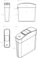
- Fig. 1 shows the front view
- Fig. 2 the side view from the left
- Fig. 3 the top view
- Fig. 4 a perspective view of a sanitary disposal unit 1.
- the sanitary disposal unit 1 may have a substantially cube-shaped configuration.
- the sanitary disposal unit 1 can have a narrow and essentially rectangular shape. That is, the sanitary disposal unit 1 has two narrow and two wide side walls. In this way, it is possible to position the sanitary disposal unit 1 in narrow installation options, for example inside a toilet cubicle next to a toilet.
- the sanitary disposal unit 1 can be designed in different sizes and thus with different capacity volumes.
- a sanitary disposal unit 1 for waste provides a capacity of 5 liters, 10 liters, 15 liters, 20 liters, 25 liters, or a capacity between 5 and 25 liters.
- the sanitary disposal unit 1 may comprise a body 2 and a lid 3, wherein the lid 3 comprises a centrally located opening 13 which, as in Fig. 1 to 4 shown, can be closed by an opening device 4.
- the cover 3 comprises a further opening, which, as in the Fig. 1 to 4 shown, can be a round hole.
- a trigger sensor 15 can detect the presence of a user of the sanitary disposal unit and transmit a trigger signal to open the opening device 4.
- the further opening is useful.
- the further opening can be dispensed with.
- the body 2 has a garbage bag holder 22 for a garbage bag roll and a material holder 23 for material, for example packets with germicidal and/or odor-binding powder.
- the garbage bag roll can be inserted into the garbage bag holder at one end of the wide side wall of the body 2 and the material, for example the packages, can be inserted directly next to it between the garbage bag roll and one end of the wide side wall of the body 2 into the holders 22,23.
- a garbage bag can be arranged inside the body 2 to receive disposed waste and can be folded over the upper edge of the body 2 and/or over the fold 12 before the lid 3 is put on. Clips can be provided on the body 2 and/or on the lid 3 to attach a garbage bag. If the waste that gets into the garbage bag via the opening device 4 is to be removed, the garbage bag and the waste can be replaced with a new garbage bag when the lid 3 is removed.
- a germicidal and/or odor-binding coating and/or a suitable granulate can be provided inside a garbage bag.
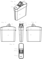
- Fig. 10 shows a side view from the left and Fig. 11 a side view from the right of an arrangement of Fig. 5 to 9
- This arrangement consists of the technology package 5, the opening device 4 and the connecting device 17.
- Fig. 10 clearly shows the release device 6 in the form of a release pin 7.
- the release device 6 can, for example, be mounted on a spring, whereby the release device 6 is pressed downwards in the unloaded state and is thus extended. If the release device 6 is pressed upwards, the release device 6 can be retracted and the opening function of the sanitary disposal unit 1 can thus be activated. Only in the activated state can the opening device 4 be actuated via the actuator 14 in order to put the sanitary disposal unit 1 into the open state. In the non-activated state, the actuator 14 cannot be actuated, even if a user approaches the trigger sensor 15 and/or a trigger signal is sent from the trigger sensor 15.
- the activation of the technology package 5 by the activation device 6 pushed upwards or retracted can be carried out, for example, by placing the cover 3 on the body 2, wherein at the same time the activation device 6, which is installed in the cover 2 with the technology package 5, is placed on a side wall 8 of the body 2 and is thus pushed upwards and retracted.
- Fig. 11 shows the opening device 4 in the closed state.
- the opening device 4 is connected to the actuator 14 via the connecting device 17.
- the actuator 14 is a lever which is connected at its first, upper end via an actuator shaft 32 to the interior of the technology package 5, preferably a drive.
- the actuator 14 can be pivotally mounted within a certain angular range via such an actuator shaft 32.
- At the opposite, second end of the actuator 14 there is a projection which is connected to a hook of the connecting device 17.
- the actuator 14 is in an end position in which the lower end of the actuator 14, specifically the projection of the actuator 14, is oriented in the direction of the opening device 4.
- the actuator 14 can be moved into a second position by rotating the actuator shaft 32, in Fig. 18 shown end position so that the lower end of the actuator 14, specifically the projection of the actuator 14, is oriented away from the opening device 4.
- a trigger signal can lead to an actuation of the actuator 14, whereby the projection of the actuator 14, which is connected to the hook of the connecting device 17, moves away from the opening device 4, specifically away.
- the connecting device 17 is pulled along by the projection of the actuator 14.
- the structural connection of the connecting device 17 with the opening device 4 the opening of the opening device 4 preferably a folding of the opening device 4. If the actuator 14 moves back to its original, specifically closed, position, the opening device 4 folds back into the closed state due to gravity and thus pulls the connecting device 17 into its original and closed position, which in Fig. 11 shown.
- the structural connection between the technology package 5 and the connecting device 17 can, as in Fig. 11 shown, be designed in such a way that both an electrical actuation of the opening device 4 by the technology package and a manual actuation of the opening device 4 is possible.
- the actuator 14 can pull the connecting device 17 along and thus bring the opening device 4 into the open state.
- the opening device 4 can also be brought into the open state manually, preferably by hand by accessing the upper plate-shaped components of the opening device 4.
- the hook of the connecting device 17 slides along the projection of the actuator 14 as a result of the opening of the opening device 4, in Fig. 11 to the left.
- This guided movement of the connecting device 17 can be continued without blockage until the opening device 4 is in the open state.
- the opening device 4 can be opened on the one hand by the electrical actuation of the technology package 5 and, on the other hand, can be brought into the open and/or closed state without blockage by manually operating the opening device 4.
- the technology package can be provided to be in the closed state as standard. This standard state can be ensured by appropriate programming and/or design of the technology package 5, which moves the actuator 14 into the closed state even in the event of a fault, power failure or other situations.
- the connecting device 17 can have an overload protection 18.
- the overload protection 18 in Fig. 11 is implemented by a damping spring element, whereby the damping spring element has three elliptical components.
- the overload protection 18 is suitable for compensating mechanical forces in order to avoid damage to the connecting device 17 or components connected to it.
- the overload protection 18 shown here is particularly suitable for compensating tensile forces and compressive forces between the bearing points of the connecting device 17 with the technology package 5 and the opening device 4.
- the opening device 4 can be an opening flap, which can essentially consist of two plate-shaped components and two side panels arranged laterally between the plate-shaped components.
- the two Plate-shaped components allow the opening 13 in the lid 3 of the sanitary disposal unit 1 to be covered both when it is open and when it is closed, so that the contents of the sanitary disposal unit 1 cannot be seen.
- the side panels can be used to ensure that waste which is placed on the lower plate-shaped component for disposal does not fall to the side next to the sanitary disposal unit 1 but only into the sanitary disposal unit.
- Fig. 12 shows a perspective view
- Fig. 13 a side view from the right
- Fig. 14 a front view
- Fig. 15 a side view from the left
- Fig. 16 a plan view of the sanitary disposal unit 1, wherein the opening device 4 is in the open state.
- the opening device 4, with which the opening 13 of the sanitary disposal unit 1 can be closed and opened, can, as in Fig. 12 to 16 shown, be arranged in the cover 3 in such a way that the opening device 4 opens in the direction of a narrow side of the sanitary disposal unit 1.
- This orientation of the opening device 4 enables a high degree of flexibility of the sanitary disposal unit 1 in a wide variety of locations and in a wide variety of positions.
- the sanitary disposal unit 1 can thus be positioned on both the right and left side of a toilet in a space-saving and at the same time easily accessible manner, without the need for conversion and/or twisted placement of the cover 3 by maintenance personnel and/or a inconvenient handling by a user is necessary when disposing of waste.
- this plate-shaped component allows a user of the sanitary disposal unit 1 to place waste on this plate-shaped component before it is discharged into the interior of the sanitary disposal unit 1 when the opening device 4 is closed.
- the opening device 4 shown here can be equipped with an insert 25, wherein the insert 25 is arranged directly on the opening device 4 and has a shape corresponding to the opening device 4.
- the insert 25 can improve the hygienic conditions in that the insert 25 is, for example, easier to replace than the opening device 4 and/or is coated with germicidal and/or odor-binding material.
- Fig. 17 shows a bottom view
- Fig. 18 a side view from the right
- Fig. 19 a front view
- Fig. 20 a side view from the left
- Fig. 21 a top view
- Fig. 22 a perspective view of the arrangement from the Fig. 10 and 11 .
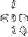
- Fig. 23 shows a perspective view from above, Fig. 24 a bottom view, Fig. 25 a first perspective view from below, Fig. 26 a second perspective view from below of an arrangement of the cover 3 and the installed technology package 5.
- Fig. 23 the lid 3 can be seen without the opening device 4, wherein a recessed grip 19 is provided on an edge of the opening 13 of the lid 3, in which the opening device 4 can be arranged.
- the recessed grip 19 can serve to make it easier for a user to access the opening device 4 if the opening device 4 is to be opened manually.
- the Fig. 25 and 26 show opening pivot points 27 at which the opening device 4 can be rotatably mounted.
- the Fig. 24 , 25 and 26 show the technology package 5 in the installed state within the cover 3.
- Two elastic snap connections 16 are provided for installing the technology package 5 in the cover 3 and for holding the technology package 5 within the cover 3.
- the elastic snap connections 16 can be displaced by corresponding snap projections 33 of the technology package 5. If the insertion movement of the technology package 5 is carried out up to the Fig. 25 and 26 shown position, the snap projections 33 of the technology package 5 engage in recesses of the elastic snap connections 16 of the cover 3 and thus hold the technology package 5 in the installed state.
- the cover 3 can then be placed on the body 2. Placing the arrangement of the cover 3 and the built-in technology package 5 can result in a further positive and/or non-positive connection.
- a clamping lever 20 of the body 2 can be used, see Fig. 2 , 5 and 7 , engage in a clamping lever receptacle 26 of the cover 3 and thus hold the cover 3 placed on the body 2.
- the lid 3 is first removed from the body 2, whereby the connection between the body 2 and the lid 3 can be released by pressing the clamping lever 20.
- the elastic snap connections 16 can then be pushed to the side, preferably manually, so that the technology package 5 including its snap projections 33 can be moved past the elastic snap connections 16 and lifted out of the lid 3.
- the clamping lever 20 and the clamping lever receptacle 26 can preferably be designed in such a way that the lid 3 can engage with the body 2 when it is put on. It can also be provided that the lid 3 can also be rotated by 180 degrees and then put on so that the clamping lever 20 is arranged on one narrow side of the sanitary disposal unit 1 and the clamping lever receptacle 26 is arranged on the other, opposite narrow side of the sanitary disposal unit 1. This means that it can be provided that the orientation of the opening device 4 can be changed by twisting the lid 3 on the body 2 without having to rotate the entire sanitary disposal unit 1.
- Fig. 27 and 28 show the cover 3 without the technology package 5, whereby the elastic snap connections 16 are more clearly visible.
- the elastic snap connections 16 can be designed in the form of clamping tongues 29, each with a clamping tongue recess 30 for receiving a snap projection 33.
- connection between the technology package 5 and the cover 3 is merely an exemplary embodiment and is not to be understood as limiting.
- the connection between the technology package 5 and the cover 3 is established by a frictional connection or that the installed technology package is connected to the body 2 instead of to the cover 3.
- Fig. 29 shows a top view of the arrangement of cover 3 and technology package 5.
- the Fig. 30 shows a cross-section of Fig. 29.
- Fig. 31 shows a bottom view of the cover 3 without technology package 5.
- Fig. 32 shows a cross-section of Fig. 31.
- Fig. 33 shows a detailed view of Fig. 32 .
- Fig. 30 a section through the arrangement of cover 3 and installed technology package 5 is shown, wherein an energy storage device 28 arranged within the technology package 5 and the trigger sensor 15 can be seen.
- the energy storage device 28 may be a battery, a rechargeable accumulator, a network connection to a power supply network or in the form of another energy source.
- Fig. 33 shows one of the two clamping tongues 29 and the clamping tongue recess 30 arranged therein, into which a snap projection 33 of the technology package 5 can snap into place.
- Fig. 34 shows a bottom view
- Fig. 35 a side view from the right
- Fig. 36 a front view
- Fig. 37 a side view from the left
- Fig. 38 a perspective view
- Fig. 39 a top view of the technology package 5.
- the technology package 5 shown here has an actuator 14, an activation device 6, two snap projections 33, a trigger sensor 15 and an energy flap 21.
- the actuator 14 can be designed in the form of a lever, which can be connected to the interior of the technology package 5, in particular a drive, via an actuator shaft 32.
- the A non-destructively detachable connection can be established with the connecting device 17.
- the energy flap 21 can be pivotally opened or closed via an axis of the flap pivot point 24, whereby the flap pivot point 24 can be located on the top of the technology package 5.
- the energy storage device 28 In the open state, the energy storage device 28 can be removed or inserted.
- Two energy flap grids 31 can be provided to fix the energy flap 21, which are located on the underside of the technology package 5.
- Fig. 40 shows a front view and Fig. 41 a side view of a handle device 9.
- the handle device 9 can have a carrying handle 10 and carrying projections 11.
- a fold 12 can be seen at the upper end of the body 2.
- a sanitary disposal unit 1 can be easily transported using the carrying device 9. To do this, a member of the maintenance staff takes the handle device 9 on the carrying handle 10 and inserts one of the carrying projections 11 from below into the fold 12 of the body 2. The body 2 and/or the entire sanitary disposal unit 1 can then be lifted and transported using the carrying projection 11 and the fold 12.
- a wall mounting device can also be provided.
- a fastening device for fastening the wall mounting device to a wall, for example holes for screws.
- a wall mounting device has projections for holding a sanitary disposal unit 1.
- Fig. 42 shows a schematic flow diagram of a method for maintaining a sanitary disposal unit 1.
- a method according to the invention for maintaining a sanitary disposal unit 1 comprises at least the method steps A, B, C, D and E. The remaining method steps can be added individually and optionally.
Landscapes
- Engineering & Computer Science (AREA)
- Mechanical Engineering (AREA)
- Refuse Receptacles (AREA)
- Processing Of Solid Wastes (AREA)
Applications Claiming Priority (1)
| Application Number | Priority Date | Filing Date | Title |
|---|---|---|---|
| ATA50499/2023A AT527428A1 (de) | 2023-06-23 | 2023-06-23 | Sanitärentsorgungseinheit, Verfahren zur Instandhaltung einer Sanitärentsorgungseinheit und Technikpaket für eine Sanitärentsorgungseinheit |
Publications (2)
| Publication Number | Publication Date |
|---|---|
| EP4491539A2 true EP4491539A2 (fr) | 2025-01-15 |
| EP4491539A3 EP4491539A3 (fr) | 2025-03-12 |
Family
ID=91076838
Family Applications (1)
| Application Number | Title | Priority Date | Filing Date |
|---|---|---|---|
| EP24175438.1A Pending EP4491539A3 (fr) | 2023-06-23 | 2024-05-13 | Unité d'évacuation sanitaire et procédé d'entretien d'une unité d'évacuation sanitaire |
Country Status (2)
| Country | Link |
|---|---|
| EP (1) | EP4491539A3 (fr) |
| AT (1) | AT527428A1 (fr) |
Family Cites Families (7)
| Publication number | Priority date | Publication date | Assignee | Title |
|---|---|---|---|---|
| GB9720055D0 (en) * | 1997-09-19 | 1997-11-19 | Kennedy Eng Holding David | Bins with opening lids |
| NL1027224C2 (nl) * | 2004-10-12 | 2006-04-13 | Brabantia Nederland Bv | Houder met elektrisch bedienbaar deksel. |
| DE102005044616A1 (de) * | 2005-02-10 | 2006-08-24 | Westermann Kg | Abfallsammler |
| US9790025B2 (en) * | 2012-03-09 | 2017-10-17 | Simplehuman, Llc | Trash can with clutch mechanism |
| CA2941812A1 (fr) * | 2015-09-16 | 2017-03-16 | Frank Yang | Contenants comportant plusieurs detecteurs |
| WO2020108658A1 (fr) * | 2018-11-30 | 2020-06-04 | 苏州宝时得电动工具有限公司 | Système intelligent de déplacement d'ordures et procédé d'entraînement de poubelle associé |
| US11505402B2 (en) * | 2019-06-13 | 2022-11-22 | Nine Stars Group (U.S.A.) Inc. | Trash container |
-
2023
- 2023-06-23 AT ATA50499/2023A patent/AT527428A1/de unknown
-
2024
- 2024-05-13 EP EP24175438.1A patent/EP4491539A3/fr active Pending
Also Published As
| Publication number | Publication date |
|---|---|
| EP4491539A3 (fr) | 2025-03-12 |
| AT527428A1 (de) | 2025-01-15 |
Similar Documents
| Publication | Publication Date | Title |
|---|---|---|
| EP0931005B1 (fr) | Conteneur pour materiaux pollues et/ou contamines | |
| DE102019128051B4 (de) | Saugreinigungsgerät mit einem eine Filterkammer verschließenden Kammerdeckel | |
| DE102014209510B3 (de) | Klappbox | |
| DE2245917B2 (de) | Vorrichtung zum entleeren eines sammelbehaelters fuer muenzen | |
| DE69520949T2 (de) | Vorrichtung zum einbringen eines schirms in eine hülle | |
| AT527428A1 (de) | Sanitärentsorgungseinheit, Verfahren zur Instandhaltung einer Sanitärentsorgungseinheit und Technikpaket für eine Sanitärentsorgungseinheit | |
| EP2613893B1 (fr) | Système de nettoyage de contenants et procédé de nettoyage | |
| WO2002051686A1 (fr) | Chariot transporteur pour le nettoyage industriel de batiments | |
| EP2657153A1 (fr) | Récipient de collecte de déchets | |
| DE102009021653A1 (de) | Anordnung zur Entsorgung von Resturin nach dem Gebrauch eines Urinals | |
| DE102022106261A1 (de) | Container für Hausabfälle | |
| DE3739036A1 (de) | Elektrisches haushaltgeraet mit einem schrankfoermigen aussengehaeuse | |
| DE202005008791U1 (de) | Reinigungswagen und Deckel hierfür | |
| EP0432643A1 (fr) | Cabinet d'aisances à sec | |
| DE20010772U1 (de) | Müllbehälter mit einer Müllzerkleinerungsvorrichtung | |
| DE102006029800A1 (de) | Toilettensystem, insbesondere für Verkehrsmittel | |
| DE102019005035A1 (de) | Geruchsdichtes Behältnis für Resteentsorung | |
| DE9115348U1 (de) | Straßenmöbel zur Abfallentsorgung, mit Werbemitteln | |
| DE60311814T2 (de) | Küchenmöbel zur Aufnahme eines Müllbehälters | |
| DE202015105523U1 (de) | Wasserloses Toilettensystem | |
| EP2923617A1 (fr) | Dispositif destiné à la livraison de marchandises | |
| DE102017102846B4 (de) | Deckel für einen Müllaufnahmebehälter und Vorrichtung zum Sammeln von Müll | |
| DE202020101738U1 (de) | Hygienestation | |
| DE102015003416B4 (de) | Vorrichtung zu Aufnahme, Transport und Entsorgung von Exkrementen (Kot) sowie Roll-Leinenbox oder Hundeleine mit einer solchen Vorrichtung | |
| DE3630894A1 (de) | Abfallbehaelter mit schieber |
Legal Events
| Date | Code | Title | Description |
|---|---|---|---|
| PUAI | Public reference made under article 153(3) epc to a published international application that has entered the european phase |
Free format text: ORIGINAL CODE: 0009012 |
|
| STAA | Information on the status of an ep patent application or granted ep patent |
Free format text: STATUS: THE APPLICATION HAS BEEN PUBLISHED |
|
| AK | Designated contracting states |
Kind code of ref document: A2 Designated state(s): AL AT BE BG CH CY CZ DE DK EE ES FI FR GB GR HR HU IE IS IT LI LT LU LV MC ME MK MT NL NO PL PT RO RS SE SI SK SM TR |
|
| PUAL | Search report despatched |
Free format text: ORIGINAL CODE: 0009013 |
|
| AK | Designated contracting states |
Kind code of ref document: A3 Designated state(s): AL AT BE BG CH CY CZ DE DK EE ES FI FR GB GR HR HU IE IS IT LI LT LU LV MC ME MK MT NL NO PL PT RO RS SE SI SK SM TR |
|
| RIC1 | Information provided on ipc code assigned before grant |
Ipc: B65F 1/14 20060101ALI20250206BHEP Ipc: B65F 1/16 20060101AFI20250206BHEP |
|
| STAA | Information on the status of an ep patent application or granted ep patent |
Free format text: STATUS: REQUEST FOR EXAMINATION WAS MADE |
|
| 17P | Request for examination filed |
Effective date: 20250902 |