EP4491560A1 - Connecteur d'ascenseur avec caractéristique d'alignement - Google Patents
Connecteur d'ascenseur avec caractéristique d'alignement Download PDFInfo
- Publication number
- EP4491560A1 EP4491560A1 EP24188395.8A EP24188395A EP4491560A1 EP 4491560 A1 EP4491560 A1 EP 4491560A1 EP 24188395 A EP24188395 A EP 24188395A EP 4491560 A1 EP4491560 A1 EP 4491560A1
- Authority
- EP
- European Patent Office
- Prior art keywords
- suspension member
- end wall
- wall
- internal cavity
- connector
- Prior art date
- Legal status (The legal status is an assumption and is not a legal conclusion. Google has not performed a legal analysis and makes no representation as to the accuracy of the status listed.)
- Pending
Links
Images

Classifications
-
- B—PERFORMING OPERATIONS; TRANSPORTING
- B66—HOISTING; LIFTING; HAULING
- B66B—ELEVATORS; ESCALATORS OR MOVING WALKWAYS
- B66B7/00—Other common features of elevators
- B66B7/12—Checking, lubricating, or cleaning means for ropes, cables or guides
- B66B7/1207—Checking means
- B66B7/1215—Checking means specially adapted for ropes or cables
- B66B7/1223—Checking means specially adapted for ropes or cables by analysing electric variables
-
- B—PERFORMING OPERATIONS; TRANSPORTING
- B66—HOISTING; LIFTING; HAULING
- B66B—ELEVATORS; ESCALATORS OR MOVING WALKWAYS
- B66B7/00—Other common features of elevators
- B66B7/06—Arrangements of ropes or cables
-
- B—PERFORMING OPERATIONS; TRANSPORTING
- B66—HOISTING; LIFTING; HAULING
- B66B—ELEVATORS; ESCALATORS OR MOVING WALKWAYS
- B66B19/00—Mining-hoist operation
- B66B19/02—Installing or exchanging ropes or cables
-
- B—PERFORMING OPERATIONS; TRANSPORTING
- B66—HOISTING; LIFTING; HAULING
- B66B—ELEVATORS; ESCALATORS OR MOVING WALKWAYS
- B66B7/00—Other common features of elevators
- B66B7/06—Arrangements of ropes or cables
- B66B7/062—Belts
-
- B—PERFORMING OPERATIONS; TRANSPORTING
- B66—HOISTING; LIFTING; HAULING
- B66B—ELEVATORS; ESCALATORS OR MOVING WALKWAYS
- B66B7/00—Other common features of elevators
- B66B7/12—Checking, lubricating, or cleaning means for ropes, cables or guides
- B66B7/1207—Checking means
- B66B7/1215—Checking means specially adapted for ropes or cables
Definitions
- Elevator systems are in widespread use for carrying passengers between various levels in buildings, for example.
- Some elevator systems are traction-based in which a suspension assembly, sometimes referred to as roping, suspends the elevator car and a counterweight.
- the suspension assembly also facilitates movement of the elevator car when needed.
- Traditional suspension assemblies include round steel ropes.
- elevator systems have included other types of suspension members, such as flat belts or other types of ropes that have tension members encased in a compressible polymer jacket.
- An illustrative example connector includes: a body defining an internal cavity configured to receive a suspension member of an elevator system; at least one suspension member alignment feature formed on an inner wall surface that surrounds the internal cavity; and a plurality of contact members that establish electrically conductive connections with tension members in the suspension member, wherein the at least one suspension member alignment feature aligns the contact members with the tension members.
- Particular embodiments further may include at least one, or a plurality of, the following optional features, alone or in combination with each other:
- the at least one suspension member alignment feature comprises at least one contact surface that extends at an angle relative to the inner wall surface.
- the at least one contact surface comprises a key that is centered within the internal cavity.
- the at least one contact surface comprises at least one resilient finger.
- the internal cavity is defined by a width extending from a first end wall of the internal cavity to a second end wall of the internal cavity that is opposite of the first end wall, and wherein the at least one contact surface comprises an angled surface that extends at an angle relative to the first end wall to provide a first end wall shape for the first end wall.
- the second end wall has a second end wall shape that is different than the first end wall shape.
- the body has a first wall, a second wall opposite the first wall, a first end wall connecting one end of the first wall to one end of the second wall, and a second end wall connecting an opposite end of the first wall to an opposite end of the second wall, and wherein one of the first wall and second wall includes a plurality of openings that each receive one contact member.
- An illustrative example elevator system includes: an elevator car; at least one suspension member that supports the elevator car and facilitates movement of the elevator car; a connector defining an internal cavity that is enclosed by a plurality of walls, wherein a portion of the at least one suspension member extends into the internal cavity; at least one alignment feature formed within the internal cavity, the at least one alignment feature to directly engage the at least one suspension member; and a plurality of contact members that establish electrically conductive connections with tension members in the at least one suspension member, and wherein the at least one alignment feature aligns the contact members with the tension members.
- Particular embodiments further may include at least one, or a plurality of, the following optional features, alone or in combination with each other:
- the at least one alignment feature comprises at least one contact surface that extends at an angle relative to at least one wall surface of the plurality of walls that define the internal cavity.
- the at least one contact surface comprises a key that is centered within the internal cavity.
- the at least one contact surface comprises at least one resilient finger.
- the at least one resilient finger comprises at least a pair of resilient fingers with one finger being on one side of the internal cavity and another finger being on an opposite side of the internal cavity.
- the internal cavity is defined by a width extending from a first end wall of the plurality of walls to a second end wall of the plurality of walls that is opposite of the first end wall, and wherein the at least one contact surface comprises an angled surface that extends at an angle relative to the first end wall to provide a first end wall shape, and wherein the second end wall has a second end wall shape that is different than the first end wall shape.
- the at least one suspension member comprises a first edge extending along a length of the at least one suspension member and a second edge that is opposite of the first edge, and wherein the first edge has a first edge shape that matches the first end wall shape and the second edge has a second edge shape that matches the second end wall shape.
- the at least one suspension member comprises a flat belt including the tension members encased in a jacket, wherein at least one wall of the plurality of walls includes a plurality of openings to receive the contact members that directly engage with the at least one suspension member via the plurality of openings.
- a center contact member of the plurality of contact members is aligned at a center of the at least one suspension member at a location that is between two adjacent tension members.
- An illustrative example method of aligning a suspension member within an internal cavity of a connector includes: forming at least one alignment feature on an inner wall surface that surrounds the internal cavity; directly engaging a suspension member surface against the at least one alignment feature to provide a properly aligned position of the suspension member within the internal cavity; and establishing electrically conductive connections between a plurality of contact members and tension members in the suspension member in response to the at least one alignment feature aligning the contact members with the tension members.
- Particular embodiments further may include at least one, or a plurality of, the following optional features, alone or in combination with each other:
- the suspension member comprises a flat belt including the tension members encased in a jacket
- the method includes: inserting the contact members through a wall of the connector such that, when in the properly aligned position, a center contact member of the plurality of contact members is aligned at a center of the suspension member at a location that is between two adjacent tension members.
- the method includes forming a first end wall of the internal cavity to have a first end wall shape to provide the at least one alignment feature, forming a second end wall of the internal cavity to have a second end wall shape different from the first end wall shape, forming a first longitudinal edge of the suspension member to have a first edge shape that matches the first end wall shape, and forming a second longitudinal edge of the suspension member to have a second edge shape that matches the second end wall shape.
- the method includes forming at least one key or finger to extend outwardly of the inner wall surface to provide the at least one alignment feature.
- Embodiments of this disclosure provide a connector with an internal cavity configured to receive a suspension member and an alignment feature formed on an inner wall surface that surrounds the internal cavity.
- the connector includes contact members that establish electrically conductive connections with tension members in the suspension member, with the alignment feature aligning the contact members with the tension members via a common reference.
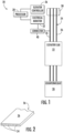
- FIG. 1 schematically illustrates selected portions of an elevator system 20.
- An elevator car 22 is supported by a roping arrangement or suspension assembly 24 that includes a plurality of suspension members 26.
- the elevator car 22 is coupled to a counterweight 28 by the suspension members 26.
- the suspension members 26 move around a sheave 38 as the elevator car 22 moves between landings or levels.
- a suspension member monitoring device includes at least one processor 30 that is configured to determine a condition of each of the suspension members 26.
- the processor 30 in the illustrated example includes a computing device and associated memory.
- the processor 30 is programmed or otherwise configured to use different types of information indicative of the respective conditions of the suspension members 26 and a combination of criteria to determine when it is desirable or necessary to remove any one of the suspension members 26 from service.
- An electric-based monitor 32 uses an electrical inspection technique and generates or provides a corresponding indication regarding a condition of each suspension member 26.
- the processor 30 receives the indication from the electric-based monitor 32.
- the electric-based monitor 32 is configured to apply electricity to at least one of the tension members, such as a steel cord, of each suspension member 26 and to detect or measure the electrical resistance of the tension member. Changes in the electrical resistance indicate changes in a condition of the suspension member 26. Such resistance-based inspection techniques are known and need not be further described here.
- FIG. 2 schematically illustrates a portion of an example suspension member 26.
- the suspension member 26 is a flat belt including a plurality of tension members 34 encased in a jacket 36 of a compressible material, such as polyurethane.
- the tension members 34 comprise steel cords.
- Other embodiments include tension members that are made of different materials.
- the electrical inspection technique takes advantage of the electrically conductive nature of the tension members 34.
- a connector 40 is used to connect the electric-based monitor 32 to an associated suspension member 26 ( Figure 1 ).
- the electric-based monitor 32 wirelessly communicates the electrical resistance information to the processor 30.
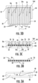
- the connector 40 defines an internal cavity 42 that is enclosed by a plurality of walls.
- the plurality of walls include a first wall 44, a second wall 46 opposite the first wall 44, a first end wall 48 connecting one end of the first wall 44 to one end of the second wall 46, and a second end wall 50 connecting an opposite end of the first wall 44 to an opposite end of the second wall 46.
- the plurality of walls 44, 46, 48, 50 cooperate to completely surround and enclose the internal cavity 42.
- One portion 52 of the suspension member 26 extends into the internal cavity 42 as shown in Figure 3D .
- Figures 3A-3C show an example of an alignment feature 54 that is formed within the internal cavity 42.
- the at least one alignment feature 54 is configured to directly engage the suspension member 26.
- the connector 40 further includes a plurality of contact members 56 ( Figure 3C ) that establish electrically conductive connections with the tension members 34 in the suspension member 26.
- the alignment feature 54 aligns the contact members 56 and the tension members 34 to a common reference R to reduce potential misalignment between the suspension member 26 and the contact members 56. If there is mis-alignment, one of the tension members 34 may not have an electrically conductive connection with one of the contact members 56, which would mean that there would be no electrical resistance information for that tension member 34.
- the alignment feature 54 comprises at least one contact surface that extends at an angle relative to at least one wall surface of the plurality of walls 44, 46, 48, 50 that define the internal cavity 42.
- the contact surface comprises a small portion of a wall surface that extends at an angle relative to a main wall surface.
- the alignment feature 54 comprises a contact surface that is formed as at least one protrusion or recess within at least one wall surface of the plurality of walls that define the internal cavity 42.
- Figures 3A-3C disclose an example where the contact surface of the alignment feature 54 comprises a key 58 that protrudes outwardly from the wall 46.
- the key 58 has a first surface extending at an angle relative to an inner wall surface 88 of the second wall 46, a second surface extending at an angle relative to the inner wall surface 88 of the second wall 46, and a third surface that connects the first and second surfaces.
- the alignment feature 54 further comprises a receiver area 60 that is formed within the suspension member 26 as shown in Figure 3B .
- a cross-sectional shape of the receiver area 60 corresponds or matches to the cross-sectional shape of the key 58.
- the receiver area 60 is formed within the jacket 36 during production of the belt to extend along an entirety of a length of the suspension member 26. This would allow the connector 40 to be used anywhere on the suspension member 26.
- the key 58 has a trapezoidal cross-section; however, other cross-sectional shapes could also be used.
- the key 58 could have a triangular cross-section, square cross-section, or any other polygonal shape.
- the key 58 could have a curved cross-section or a cross-section having a combination of curved and linear shapes.
- the key 58 is centered within the internal cavity 42 as shown in Figures 3A-3C .
- the key 58 is inserted within the receiver area 60 as shown in Figure 3C .
- this example uses a feature created during belt production that mates to a feature on the connector 40 to align to a common reference R.
- a proper alignment comprises a configuration where each tension member 34 is in contact with one of the contact members 56 as shown in Figure 3D .
- the contact members 56 comprise screws or other similar fastening elements.
- a center contact member 56a is aligned at a center of the suspension member 26 at a location that is between two adjacent tension members 34a, 34b that are located at the middle of the suspension member 26.
- one side of the center contact member 56a contacts tension member 34a and an opposite side of the center contact member 56a contacts tension member 34b.
- the edge tension members 34c, 34d each directly, and respectively, only engage with end contact members 56c, 56d.
- the remaining contact members 56 are aligned between adjacent tension members 34 such that one side of the contact member 56 contacts one tension member 34 and an opposite side of the contact member 56 contacts the other tension member 34. It should be understood that twelve tension members 34 and seven contact members 56 are shown as one example, and the number of tension and contact members can be varied as needed.
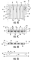
- Figures 4A-4D disclose another example of an alignment feature 54.
- the angled contact surface of the alignment feature 54 comprises a contoured portion of one of the end walls 48, 50 that defines an asymmetric feature.
- the internal cavity 42 is defined by a width extending from the first end wall 48 to the second end wall 50.
- the contact surface comprises at least one angled surface 70 that extends at an angle relative to the first end wall 48 to provide a first end wall shape.
- the contact surface comprises two angled surfaces 70 that are connected to each other via a flat surface portion of the end wall 48.
- the angled surfaces 70 extend at non-parallel and non-perpendicular angles relative to the flat surface potion.
- the second end wall 50 has a second end wall shape that is different than the first end wall shape.
- the suspension member 26 comprises a first edge 72 extending along a length of the suspension member 26 and a second edge 74 that is opposite of the first edge 72.
- the first edge 72 has a first edge shape that matches the first end wall shape and the second edge 74 has a second edge shape that matches the second end wall shape. This means that the suspension member 26 can only be installed in one orientation within the connector 40.
- the first edge 72 has angled surfaces 76 connected to each other by a straight surface 80 to form a shape common with the first end wall shape.
- the second edge 74 has a squared-off shape to match the squared-off end of the second end wall 50. It should be understood that other shapes could also be used.
- At least one resilient finger 62 is additionally used as a compliant feature to hold the first edge 72 of the suspension member in direct engagement with the first end wall 48 to achieve proper alignment.
- the alignment feature 54 comprises an asymmetric feature that is added to the suspension member 26 that allows only one installation orientation in combination with using a compliant feature to align to a common reference R.
- Figures 5A-5B disclose another example of an alignment feature 54.
- the angled contact surface of the alignment feature 54 comprises at least one resilient finger 62.
- the resilient finger 62 is formed within one of the first 48 and second 50 end walls.
- the at least one finger 62 comprises at least a pair of resilient fingers 62 with one finger 62 being on one side of the internal cavity 42 and another finger 62 being on an opposite side of the internal cavity 42 as shown in Figure 5B .
- a recess 64 for each finger 62 is formed within the associated end wall 48, 50 to be associated with the respective finger 62.
- the finger 62 has a first end 66 that is held fixed within the recess 62, and extends to a cantilevered distal end 68 that is moveable between an uninstalled position and an installed position.
- the finger 62 is resiliently biased to an outward position within the internal cavity 42 when the suspension member 26 is in the uninstalled position.
- the fingers 62 are pressed outwardly away from each other and toward their respective recesses 64 by opposing edges 72, 74 of the suspension member 26.
- the fingers 62 comprise a compliant feature that resiliently grips and centers the suspension member 26 in the properly aligned position relative to the common reference R. In this position, the contact members 56 are aligned relative to the tension members 34 in a manner similar to that described above with regard to Figure 3D .
- Figure 6 is a flowchart diagram of an example implementation of the method of alignment.
- a method of aligning a suspension member 26 within an internal cavity 42 of a connector 40 includes forming at least one alignment feature 54 on an inner wall surface that surrounds the internal cavity 42 as indicated at step 100.
- a suspension member surface is directly engaged with the at least one alignment feature 54 to provide a properly aligned position of the suspension member 26 within the internal cavity 42 as indicated at step 200.
- electrically conductive connections are established between the contact members 56 and tension members 34 in the suspension member 26 in response to the at least one alignment feature 54 aligning the contact members 56 with the tension members 34 as indicated at step 300.
- one wall of the plurality of walls 44, 46, 48, 50 is formed to have openings 78 to receive the contact members 56 that directly engage with the tension members 34.
- step 300 of the method further includes inserting the contact members 56 through the wall of the connector 40 such that, when in the properly aligned position, a center contact member 56a of the plurality of contact members 56 is aligned at a center of the suspension member 26 at a location that is between two adjacent tension members 34a, 34b.
- forming the at least one alignment feature 54 comprises forming an asymmetric feature as set forth at step 110.
- step 110 includes: forming a first end wall of the internal cavity to have a first end wall shape to provide the at least one alignment feature; forming a second end wall of the internal cavity to have a second end wall shape different from the first end wall shape; forming a first longitudinal edge of the suspension member to have a first edge shape that matches the first end wall shape; and forming a second longitudinal edge of the suspension member to have a second edge shape that matches the second end wall shape.
- forming the at least one alignment feature 54 comprises forming a protruding feature as set forth at step 120.
- step 120 includes forming at least one key or finger to extend outwardly of the inner wall surface to provide the at least one alignment feature.
- the subject disclosure provides several methods for reducing potential misalignment between the contact members and the tension members. These methods include using mating male/female features on the connector and suspension member, using compliant features inside the connector to center the suspension member, or adding a feature to ensure one installation orientation while using a compliant feature to align to a common reference. By creating a single common reference from which all tension members on the suspension member and contact members on the connector are dimensioned and controlled, the dependence on dimensions such as the connector slot width, suspension member width, and tension member to edge positioning can be removed from the tolerance stack.
Landscapes
- Details Of Connecting Devices For Male And Female Coupling (AREA)
Applications Claiming Priority (1)
| Application Number | Priority Date | Filing Date | Title |
|---|---|---|---|
| US18/222,189 US20250019206A1 (en) | 2023-07-14 | 2023-07-14 | Elevator connector with alignment feature |
Publications (1)
| Publication Number | Publication Date |
|---|---|
| EP4491560A1 true EP4491560A1 (fr) | 2025-01-15 |
Family
ID=91946763
Family Applications (1)
| Application Number | Title | Priority Date | Filing Date |
|---|---|---|---|
| EP24188395.8A Pending EP4491560A1 (fr) | 2023-07-14 | 2024-07-12 | Connecteur d'ascenseur avec caractéristique d'alignement |
Country Status (3)
| Country | Link |
|---|---|
| US (1) | US20250019206A1 (fr) |
| EP (1) | EP4491560A1 (fr) |
| CN (1) | CN119306088A (fr) |
Families Citing this family (1)
| Publication number | Priority date | Publication date | Assignee | Title |
|---|---|---|---|---|
| US12091287B1 (en) * | 2023-08-01 | 2024-09-17 | Otis Elevator Company | Elevator connector with angled interface |
Citations (3)
| Publication number | Priority date | Publication date | Assignee | Title |
|---|---|---|---|---|
| WO2018141554A1 (fr) * | 2017-01-31 | 2018-08-09 | Inventio Ag | Configuration d'élément de suspension d'un ascenseur et configuration de surveillance afin de surveiller un élément de suspension |
| CN114988250A (zh) * | 2021-03-01 | 2022-09-02 | 迅达(中国)电梯有限公司 | 曳引构件的检测装置、检测方法以及电梯系统 |
| US11634302B2 (en) * | 2021-09-03 | 2023-04-25 | Weidmüller Interface GmbH & Co. KG | Elevator belt monitoring apparatus and blade contact |
-
2023
- 2023-07-14 US US18/222,189 patent/US20250019206A1/en active Pending
-
2024
- 2024-07-02 CN CN202410876225.7A patent/CN119306088A/zh active Pending
- 2024-07-12 EP EP24188395.8A patent/EP4491560A1/fr active Pending
Patent Citations (3)
| Publication number | Priority date | Publication date | Assignee | Title |
|---|---|---|---|---|
| WO2018141554A1 (fr) * | 2017-01-31 | 2018-08-09 | Inventio Ag | Configuration d'élément de suspension d'un ascenseur et configuration de surveillance afin de surveiller un élément de suspension |
| CN114988250A (zh) * | 2021-03-01 | 2022-09-02 | 迅达(中国)电梯有限公司 | 曳引构件的检测装置、检测方法以及电梯系统 |
| US11634302B2 (en) * | 2021-09-03 | 2023-04-25 | Weidmüller Interface GmbH & Co. KG | Elevator belt monitoring apparatus and blade contact |
Also Published As
| Publication number | Publication date |
|---|---|
| CN119306088A (zh) | 2025-01-14 |
| US20250019206A1 (en) | 2025-01-16 |
Similar Documents
| Publication | Publication Date | Title |
|---|---|---|
| US7506728B2 (en) | Electrical connector device for use with elevator load bearing members | |
| EP2534082B1 (fr) | Courroie de système d'ascenseur ayant des dispositifs de raccordement fixés à cette dernière | |
| US12091287B1 (en) | Elevator connector with angled interface | |
| JP3174115U (ja) | 導電部材を貫通する電気コネクタ | |
| EP4491560A1 (fr) | Connecteur d'ascenseur avec caractéristique d'alignement | |
| CA2668109C (fr) | Ensemble connecteur pour plaques conductrices | |
| US20140220835A1 (en) | Electrical Crimp Contact Device | |
| CN102216193A (zh) | 传送带 | |
| CN1926043A (zh) | 用于监测电梯的承载部件状况的电信号的应用策略 | |
| EP2819253A1 (fr) | Connecteur électrique | |
| US11174126B2 (en) | Connection element for electrically contacting tension members in a load-bearing belt for an elevator system, and method for assembling the connection element on the belt | |
| US20190345004A1 (en) | Suspension member arrangement for an elevator and monitoring arrangement for monitoring a suspension member | |
| EP3577474B1 (fr) | Élément de suspension pour un ascenseur et agencement de contrôle d'un élément de suspension | |
| US20200277162A1 (en) | Method for electrical attachment of a connecting element to a belt for an elevator system, and corresponding belt assembly | |
| CN114988250B (zh) | 曳引构件的检测装置、检测方法以及电梯系统 | |
| JPH08313581A (ja) | 端子半挿入検知用コネクタ | |
| KR102385903B1 (ko) | 커넥터 | |
| HK1178506B (en) | Assembly comprising a belt and connecting devices and method of mounting a connecting device to a belt |
Legal Events
| Date | Code | Title | Description |
|---|---|---|---|
| PUAI | Public reference made under article 153(3) epc to a published international application that has entered the european phase |
Free format text: ORIGINAL CODE: 0009012 |
|
| STAA | Information on the status of an ep patent application or granted ep patent |
Free format text: STATUS: THE APPLICATION HAS BEEN PUBLISHED |
|
| AK | Designated contracting states |
Kind code of ref document: A1 Designated state(s): AL AT BE BG CH CY CZ DE DK EE ES FI FR GB GR HR HU IE IS IT LI LT LU LV MC ME MK MT NL NO PL PT RO RS SE SI SK SM TR |
|
| STAA | Information on the status of an ep patent application or granted ep patent |
Free format text: STATUS: REQUEST FOR EXAMINATION WAS MADE |
|
| 17P | Request for examination filed |
Effective date: 20250623 |