EP4491815A1 - Dispositif de positionnement et procédé de fixation d'une deuxième partie de construction sur une première partie de construction - Google Patents
Dispositif de positionnement et procédé de fixation d'une deuxième partie de construction sur une première partie de construction Download PDFInfo
- Publication number
- EP4491815A1 EP4491815A1 EP24176170.9A EP24176170A EP4491815A1 EP 4491815 A1 EP4491815 A1 EP 4491815A1 EP 24176170 A EP24176170 A EP 24176170A EP 4491815 A1 EP4491815 A1 EP 4491815A1
- Authority
- EP
- European Patent Office
- Prior art keywords
- positioning device
- transmitting elements
- support
- force
- tensile force
- Prior art date
- Legal status (The legal status is an assumption and is not a legal conclusion. Google has not performed a legal analysis and makes no representation as to the accuracy of the status listed.)
- Pending
Links
Images





Classifications
-
- E—FIXED CONSTRUCTIONS
- E04—BUILDING
- E04C—STRUCTURAL ELEMENTS; BUILDING MATERIALS
- E04C5/00—Reinforcing elements, e.g. for concrete; Auxiliary elements therefor
- E04C5/16—Auxiliary parts for reinforcements, e.g. connectors, spacers, stirrups
- E04C5/162—Connectors or means for connecting parts for reinforcements
- E04C5/163—Connectors or means for connecting parts for reinforcements the reinforcements running in one single direction
-
- E—FIXED CONSTRUCTIONS
- E04—BUILDING
- E04B—GENERAL BUILDING CONSTRUCTIONS; WALLS, e.g. PARTITIONS; ROOFS; FLOORS; CEILINGS; INSULATION OR OTHER PROTECTION OF BUILDINGS
- E04B1/00—Constructions in general; Structures which are not restricted either to walls, e.g. partitions, or floors or ceilings or roofs
- E04B1/003—Balconies; Decks
- E04B1/0038—Anchoring devices specially adapted therefor with means for preventing cold bridging
Definitions
- the invention relates to a positioning device and a method for connecting a second structural part to a first component.
- the positioning device is designed as a solid angle and has receptacles for tension rods and holes for screwing to a connecting device. The positioning device remains in the structure.
- the present invention is based on the object of creating a positioning device of the generic type that can be used in a variety of ways.
- a further object of the invention is to provide an advantageous method for connecting a second structural part to a first structural part.
- the positioning device has at least one first support area for support against at least one tensile force-transmitting Element, wherein the first support region is formed in a first part of the positioning device, and that the positioning device has at least one second support region for support against at least one pressure force-transmitting element, wherein the second support region is formed in a second part of the positioning device.
- the first part can be fixed to the second part in at least two different positions, wherein the first support region has different distances from the at least one second support region in the at least two positions.
- the positioning device is provided in particular for a connecting device for the subsequent connection of a second structural part to a first structural part.
- Subsequent connection in this case means that the first structural part and the second structural part are manufactured and only then connected to one another.
- at least the first structural part is cast from concrete.
- first force-transmitting elements of the connecting device are embedded in the first structural part and second force-transmitting elements of the connecting device are embedded in the second structural part or fixed to it.
- the structural parts are connected to one another by connecting the first force-transmitting elements to the second force-transmitting elements.
- connecting devices In known connecting devices, the elements that transmit tensile force are often arranged in an upper area of the connecting device in the installed position and the elements that transmit compressive force are arranged in a lower area of the connecting device in the installed position.
- connecting devices with different overall heights are available. These different overall heights usually also require different distances between the compressive force-transmitting elements and the elements that transmit tensile force.
- the distance between the support areas is measured in particular in a direction that is vertical in the installation position of the connecting device. However, the distance between the support areas can also be measured in another direction. In particular, the distance is the smallest distance between the support areas.
- the positions of the first and second force-transmitting elements must be aligned with each other so that the structural components can be fixed to each other and so that all force-transmitting elements of the finished structure can absorb and transmit the intended forces.
- the distance between the support areas for the tensile force-transmitting and compressive force-transmitting elements is adjustable by fixing two parts of the positioning device to each other in different positions. This makes it easy to adjust a positioning device to the height of a connecting device, in particular on site at the construction site. There is no need to manufacture different positioning devices for different heights of connecting devices.
- the positioning device is only intended to ensure the tensile force-transmitting elements and the compressive force-transmitting elements during the manufacture of a first structural part into which the first tensile force-transmitting elements and the first compressive force-transmitting elements are integrated. After the structural part has partially or completely hardened, the positioning device can be removed and reused. This means that the structure of the structure can be made less massive than in the prior art and the positioning device can be reused in many different ways.
- the precise positioning of the tensile force-transmitting elements in relation to the compressive force-transmitting elements is particularly advantageous if a second structural part is to be subsequently connected to the first structural part.
- the subsequent connection is often done via screw connections or similar, which only allow compensation of tolerances to a limited extent.
- the at least two positions in which the first part can be fixed to the second part are structurally predetermined.
- structurally predetermined means that the first part cannot be fixed to the second part in intermediate positions in which the distance between the support areas is not defined.
- a structurally predetermined position can be structurally predetermined, for example, by the position of a stop, a fastening opening or the like.
- At least three positions are specified for fixing the first part to the second part.
- Simple adaptation to a wide range of connecting device heights can be made possible in a simple manner if the at least three positions are arranged in a predetermined grid.
- the grid dimension of the grid can in particular be at least 5 mm. In particular, the grid dimension is approximately 10 mm. Another grid dimension can also be provided. It can also be provided that the positions are specified in an irregular grid, in particular according to the available heights of connecting devices.
- At least one part has at least two fixing openings that are assigned to different positions of the first part on the second part.
- first fixing opening When the second part is fixed to the first part via a first fixing opening, a first distance between the support areas is obtained, and when it is fixed to a second fixing opening, a second, different distance between the support areas is obtained.
- second fixing opening When the second part is fixed to the first part via a first fixing opening, a first distance between the support areas is obtained, and when it is fixed to a second fixing opening, a second, different distance between the support areas is obtained.
- several fixing openings arranged as a row of holes.
- the fixing openings are arranged so as to overlap.
- the opening created is particularly similar to an elongated hole with structured, wave-shaped long sides that specify the different positions.
- fixing openings in a row of holes form a common opening.
- the fixing openings in a row of holes are in particular connected to one another, for example by an overlapping arrangement or via connecting webs. This enables efficient production of the fixing openings using a laser.
- the fixing openings can also be openings that are formed separately from one another.
- One fixing opening can be used to fix the first part to the second part. It is particularly advantageous to use two or more fixing openings for each position, so that the fixing openings form-fit the position of the two parts in relation to one another together with fastening bolts that protrude through the fixing openings.
- holes for fixing openings are provided, for example two or three rows of holes.
- a different number of rows of holes for fixing openings can also be advantageous.
- the positions of the first part on the second part are structurally predetermined via at least one positioning elevation of the one part, which projects into at least one positioning recess of the other part.
- a positioning elevation with multiple associated positioning elevations or a positioning depression with multiple associated positioning elevations can be provided.
- a simple design is obtained if both parts are designed on the sides facing each other in the manner of a toothing, in particular in the manner of a rectangular toothing, and the toothings engage with each other in the different positions of the parts relative to each other.
- the support areas can support the force-transmitting elements directly or indirectly.
- the support areas are in a structurally predetermined relative position to the tensile force transmitting elements or the compressive force transmitting elements.
- a simple design is achieved if at least one support area for the tensile force-transmitting elements is formed on an opening.
- the at least one tensile force-transmitting element is in particular inserted into the at least one opening or pushed through it. If the tensile force-transmitting element has an external thread, it can be easily fixed to the positioning device by screwing on a nut.
- the support area is formed in a sleeve.
- the sleeve can have a stiffening strut on its outside, with which it is connected to a base plate of the first part.
- Different connecting devices can differ from each other not only in the distance between the tensile force-transmitting elements and the compressive force-transmitting elements, but also in the size of the tensile force-transmitting elements and/or the compressive force-transmitting elements. If the tensile force-transmitting elements are designed as tension rods, different connecting devices can be provided with tension rods of different diameters.
- At least two adaptation sleeves are provided, which can be alternatively inserted into the at least one opening for the tensile force-transmitting elements.
- the through-openings of the at least two adaptation sleeves advantageously have different sizes, in particular different diameters. This makes it easy to adapt to different tensile force-transmitting elements.
- the adjustment sleeves in the opening are structurally predetermined and the position of the passage opening in the adjustment sleeve is provided off-center, so that the adjustment sleeve can be easily adapted not only to the different size of the tensile force-transmitting element, but also to the position of the tensile force-transmitting elements, which can vary with different diameters of the tensile force-transmitting elements.
- the second support region is formed on a front side of the second part.
- the second support region is formed on a front side of the second part that is located at the bottom in the installed position.
- a different design of the second support region for example at an opening or a slot in the second part, can also be advantageous.
- the positioning device in particular at least the second part, has a slot on at least one side, in particular on both sides of the second support area.
- the tensile force transmitting elements in particular comprise a support angle which has side cheeks. The side cheeks can protrude into the at least one slot, in particular into both slots. In particular, the side cheeks determine the position of the positioning device on the compressive force transmitting element in the horizontal direction between the side cheeks in a simple manner.
- the first part and the second part advantageously have a plate as the base body.
- the thickness of the plate is advantageously at least 3 mm, in particular at least 5 mm, in particular about 8 mm.
- the design of the first part and the second part with a base body as a plate results in a simple structure of the positioning device.
- the positioning device advantageously has means for fixing to a formwork.
- openings for nails or similar fastening means are provided as means for fixing to a formwork.
- the means for fixing to a formwork are provided in particular in the first part. It can be provided that both parts have means for fixing to a formwork.
- the positioning device advantageously has at least one support for an alignment means.
- two supports for an alignment means are provided at a distance from one another.
- the alignment means can in particular be a spirit level that is to be placed on the receptacles.
- first tensile force-transmitting elements of the connecting device and first compressive force-transmitting elements of the connecting device are positioned on a formwork for producing a first structural part, that the first part of the positioning device is fixed to the second part at a desired distance from the support areas, that the positioning device is positioned relative to the first tensile force-transmitting elements and the first compressive force-transmitting elements and that the first structural part is cast.
- the positioning device is removed and a second structural part is fixed to the first tensile force-transmitting elements and the first compressive force-transmitting elements.
- the fact that the positioning device can be adjusted to the distance between the tensile force-transmitting elements and the compressive force-transmitting elements and is removed again after the first structural part has been cast means that the positioning device can be reused.
- the first pressure-transmitting elements advantageously comprise a support angle.
- the positioning device is placed on the pressure-transmitting elements in particular on the support angle during positioning. This enables the positioning device to be arranged quickly and easily on the first structural part.
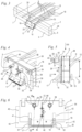
- Fig. 1 shows a schematic sectional view of a section of a building 25.
- the building 25 comprises a first building part 2, in the exemplary embodiment a building ceiling.
- a second building part 3 is fixed to the first building part 2 via a connecting device 1.
- the second building part 3 can be, for example, a balcony slab or similar cantilevered building part.
- the connecting device 1 is designed such that the second building part 3 can be fixed to the first building part 2 after the construction of the building parts 2 and 3.
- the first building part 2 is in particular a building part cast from concrete.
- the second building part 3 can also be cast from concrete.
- the load-bearing components of the second building part 3 are at least partially made of metal.
- the second building part 3 can have a balcony support structure made of steel beams.
- the connecting device 1 comprises an insulating body 5, which is arranged in a separating joint 4 between the structural parts 2 and 3.
- the connecting device 1 can also be designed without an insulating body 5.
- the connecting device 1 has a longitudinal direction 28 which, in the exemplary embodiment, runs horizontally and in the longitudinal direction of the separating joint 4.
- the longitudinal direction 28 corresponds to the longitudinal direction of the insulating body 5.
- the connecting device 1 has a transverse direction 29 which runs horizontally in particular in the installed state.
- the transverse direction 29 runs through the separating joint 4 and perpendicular to the longitudinal direction 28.
- the connecting device 1 has a vertical direction 30 which runs in the vertical direction.
- the insulating body 5 has a first longitudinal side 6 which, as Fig. 2 shows, runs adjacent to the first structural part 2.
- the insulating body 5 has an opposite second longitudinal side 7 which runs adjacent to the second structural part 3.
- a gap can be formed between the insulating body 5 and the second structural part 3.
- the second structural part 3 can also connect to the insulating body 5.
- the connecting device 1 comprises tensile force-transmitting elements 9 and 10 as well as compressive force-transmitting elements 19 and 20.
- the connecting device 1 comprises in particular transverse force-transmitting elements, in the exemplary embodiment transverse force rods 16.
- the tensile force-transmitting elements of the connecting device 1 comprise first tensile force-transmitting elements 9, which are embedded in the first structural part 2.
- the tensile force-transmitting elements of the connecting device 1 comprise second tensile force-transmitting elements 10, which are fixed to the second structural part 3.
- the second traction force transmitting elements 10 are also embedded.
- the traction force transmitting elements 9 and 10 are attached to a connecting plate 11, which is also Fig. 2 shown.
- a screw connection is provided for the connection.
- the connecting plate 11 is firmly connected to the second tensile force transmitting elements 10 in the embodiment and has openings through which the first tensile force transmitting elements 9 protrude.
- the first tensile force transmitting elements 9 are connected to the connecting plate 11 via fastening nuts 14.
- the second structural part 3 has recesses 15 in the area of the fastening nuts 14 so that the fastening nuts 14 can be subsequently applied and tightened.
- Another type of Connection of the first traction-transmitting elements 9 with the second traction-transmitting elements 10 can be provided.
- first tensile force-transmitting elements 9 are firmly connected to the connecting plate 11 and that the second tensile force-transmitting elements 10 protrude through the connecting plate 11 and are connected to the connecting plate 11 in the region of the first structural part 2 via fastening nuts 14.
- the first traction-transmitting elements 9 have longitudinal axes 12.
- the traction-transmitting elements 10 have longitudinal axes 13.
- the longitudinal axes 12 and 13 lie in particular in a common horizontal plane 24, as Fig. 1
- An offset between the longitudinal axes 12 and 13 in the vertical direction 30 can also be provided, which can be, for example, up to 20 mm, in particular up to 10 mm.
- the pressure force transmitting elements 19 comprise a support angle 17.
- the support angle 17 has a contact surface 22 and a support surface 23.
- the contact surface 22 is vertically aligned in the installed state and serves to transmit horizontally acting compressive forces.
- the support surface 23 is in particular approximately horizontally oriented in the installed state and serves to introduce vertically oriented shear forces.
- two compression rods 75 are fixed to the support angle 17 on the side facing away from the contact surface 22, which protrude into the first structural part 2 as reinforcing rods.
- a different number of compression rods 75 can also be advantageous.
- a different design of the compressive force-transmitting elements 19 can also be advantageous.
- the compressive force-transmitting elements 19 can, for example, be formed at least partially by thrust bearings and/or pressure screws.
- the support angle 17 comprises two side cheeks 18.
- Shear force rods 16 are fixed to the side cheeks 18 and are embedded in the first structural part 2.
- two shear force rods 16 are provided, but a different number of shear force rods can also be advantageous.
- the support angle 17 is formed with a section of the shear force rods 16 from a bent sheet metal.
- the first tensile force-transmitting elements 9 and the first compressive force-transmitting elements 19 are first positioned on a formwork for the production of the first structural part 2.
- the vertical distance between the support surface 23 and the first tensile force-transmitting elements 9 must be correctly coordinated with the vertical distance of the second tensile force-transmitting elements 10 and the second compressive force-transmitting elements 20 of a second structural part 3 to be connected, so that all force-transmitting elements contribute to the transmission of the acting forces in the desired manner.
- a positioning device 26 is provided, which is shown in the following figures.
- the insulating body 5 comprises a storage box 38 in which insulating material 39 is arranged.
- the insulating material 39 is made up of several parts in the embodiment and can be mineral wool, for example.
- the vertical direction 30 ( Fig. 1 ) measured height h of the insulating body 5 can be different for different connecting devices 1.
- the pressure force transmitting elements 19 have a central axis 27.
- the longitudinal axis 12 of the pressure force transmitting element 9 has a distance b from the central axis 27, which is in particular different for different heights h of the insulating body 5.
- the positioning device 26 comprises a first part 31 and a second part 32.
- the first part 31 can be fixed to the second part 32 in different positions, as will be explained in more detail below.
- the positioning device 26 can therefore be adapted to different distances b.
- the positioning device 26 has two sleeves 58, through each of which a first tensile force transmitting element 9 protrudes.
- the positioning device 26 is arranged on the long side 7 of the insulating body 5.
- the tensile force transmitting elements 9 protrude through the insulating body 5 and the positioning device 26.
- fastening nuts 43 are screwed onto each of the tension force transmitting elements 9.
- the positioning device 26 is held on the first structural part 2 by means of the fastening nuts 43.
- two tension force transmitting elements 9 are provided.
- a different number for example one, three or more tension force transmitting elements 9, can also be advantageous. Accordingly, a different number of sleeves 58 can be provided.
- the positioning device 26 rests on the support angle 17, namely on the support surface 23 of the support angle 17. As a result, the position of the pressure force transmitting element 19 in the vertical direction 30 of the connecting device 1 ( Fig. 1 ) via the positioning device 26.
- the positioning device 26 has in particular at least one support 40 which serves to support an alignment device, for example a spirit level.
- two supports 40 are provided, each of which is designed as an angle.
- the positioning device 26 can be aligned in a simple manner such that all of the first tensile force-transmitting elements 9 lie in a horizontal plane and all of the first compressive force-transmitting elements 19 lie in a horizontal plane.
- the positioning device 26 comprises a first part 31 and a second part 32.
- adjustment sleeves 35 are arranged in the sleeves 58.
- the adjustment sleeves 35 each have a web 37 which projects into a slot 36 of the sleeve 58 and thus structurally determines the rotational position of the adjustment sleeve 35.
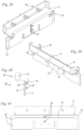
- the first part 31 can be fixed to the second part 32 in different positions. How Fig. 6 shows, the first part 31 has a plurality of fixing openings 44.
- the fixing openings 44 are arranged so as to overlap.
- the fixing openings 44 are arranged in particular at a uniform distance from one another.
- the fixing openings 44 form a row of holes.
- the distance between the fixing openings 44 corresponds to a grid dimension x for the positions of the first part 31.
- the grid dimension x can in particular be at least 5 mm, in particular approximately 10 mm.
- fixing bolts 45 - in the exemplary embodiment screws - are provided in the exemplary embodiment, onto which fixing nuts 46 - in the exemplary embodiment wing nuts - are screwed. This is also shown in the exploded view in Fig. 9 visible.
- two fixing bolts 45 and two fixing nuts 46 are provided.
- the second part 32 has through-openings 62 for the two fixing bolts 45.
- the fixing bolts 45 are always arranged in the same position on the second part 32 and the first part 31 can be fixed in a different position on the second part 32 depending on which of the fixing openings 44 the fixing bolts 45 protrude into.
- another type of fixing of the two parts 31 and 32 to one another can also be provided.
- the fixing openings 44 form a common elongated opening with structured edges.
- This elongated opening has a longitudinal axis 72 which corresponds to the direction of displacement of the first part 31 relative to the second part 32 between different positions.
- each sleeve 58 has an opening 57 through which a first tensile force transmitting element 9 protrudes.
- the openings of the sleeves 58 form a first support area 33 for the first tensile force transmitting elements 9.
- the first tensile force transmitting elements 9 rest on the first support areas 33 via the adaptation sleeves 35.
- the front side of the second part 32 which is located at the bottom in the installed state, forms a second support area 34, which rests on the support surface 23 ( Fig. 3 ) of the support bracket 17. This is also in Fig. 7 recognizable.
- the positioning aid 26 determines the position of the at least one first tensile force transmitting element 9 relative to the at least one first compressive force transmitting element 19, in the exemplary embodiment relative to the support angle 17 of the compressive force transmitting element 19.
- the Fig. 6 to 8 show the arrangement in a first position 54 of the first part 31.
- the support areas 33 have a distance a 1 from the support area 34 measured in the vertical direction 30, as Fig. 7
- the distance a 1 is measured in particular in the direction in which the position of the first part 31 can be changed relative to the second part 32.
- This direction advantageously corresponds to the vertical direction 30 of the connecting device 1. In the exemplary embodiment, this is the smallest distance between the support regions 33 and 34.
- the position of the first part 31 is variable in a direction oblique to the vertical direction 30 relative to the first part 32.
- both the first part 31 and the second part 32 have recesses in the area of the side walls 18 and the sections of the transverse force rod 16 fixed thereto.
- the first part 31 has two slot-shaped recesses 41.
- the second part 32 has two slot-shaped recesses 61.
- the recesses 61 are located in at least one position of the second part 32 on the first part 31 in Overlap to the recesses 41.
- the side cheeks 18 of the support angle 17 and the sections of the transverse force rods 16 arranged thereon come to lie in the recesses 41 and 61.
- two side cheeks 18 are provided, each with a transverse force rod 16 attached to it.
- a different number of transverse force rods 16 can also be advantageous.
- the recesses 61 and the recesses 41 are positioned in particular such that they rest against the inner sides of the side cheeks 18 of the support angle 17 or are located at a small distance from them.
- the side cheeks 18 therefore form, together with the recesses 41 and 61, a positional securing device for the positioning device 26 on the connecting device 1 in the direction of the longitudinal direction 28 of the parting line 4.
- the support areas 33 and 34 position the positioning device 26 in relation to the force-transmitting elements 9 and 19, in particular in a vertical direction in the installation position.
- the recesses 41 and 61 position the positioning device 26 in the installation position in the horizontal direction.
- Fig. 7 shows the arrangement of the support area 33 as well as the arrangement of the adaptation sleeve 35 in the sleeve 58.
- the second part 32 lies on the contact surface 22 ( Fig. 3 ) of the support angle 17. In the area protruding beyond the contact surface 22, the second part 32 is spaced from the insulating body 5.
- the second part 32 has a support web 50, over which it can be moved in its Fig. 7 area shown above on the insulating body 5.
- Fig. 7 shows, the pressure force transmitting elements 19 of the embodiment according to Fig. 5 to 8 the support angle 17, three compression rods 51 and a compression plate 52 on each compression rod 51.
- the compression plates 52 are intended to be embedded in the first structural part 2.
- the compression plates 52 are located at a small distance from the insulating body 5.
- each pressure rod 51 is fixed to the support bracket 17 via a nut 63. Another type of fixing of the pressure rod 51 to the support bracket 17 can also be provided.
- the pressure rods 51 and pressure plates 52 are an alternative design to the one shown in Fig. 3 shown version with compression rods 75.
- a plurality of disks 21 lie on the support surface 23, which secure the positioning device 26 to the support angle 17. Another type of securing can also be provided.
- the disks 21 are in particular fixed to the support surface 23 by means of screws (not shown).
- the second part 32 has recesses 47 adjacent to its upper end face through which the first tensile force transmitting elements 9 can pass.
- the second part 32 has fastening openings 42.
- the fastening openings 42 are designed as comparatively small holes.
- the fastening openings 42 are located in an area of the second part 32 that protrudes beyond the first part 31 in every position of the first part 31.
- the positioning device 26 can be fixed to a formwork for the first building part 2 at the fastening openings 42, for example with nails.
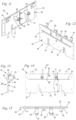
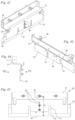
- the Figures 10 to 15 show the positioning device 26 in a second position 55 of the first part 31 on the second part 32.
- the second position 55 corresponds to a distance a 2 between the support areas 33 and 34, which in Fig. 14 is drawn in.
- the distance a 2 is the minimum adjustable distance between the support areas 33 and 34.
- the distance a 2 is also measured parallel to the longitudinal axis 72 of the opening formed by the fixing openings 44, i.e. in the direction in which the first part 31 can be moved relative to the second part 32 between the different positions.
- the recesses 41 and 61 ( Fig. 11 and 12 ) in particular largely in overlap.
- the sleeves 58 are fixed to a base plate 81 of the first part 31 via stiffening webs 48.
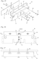
- the Fig. 16 to 20 show the positioning device 26 in a third position 56 of the first part 31 relative to the second part 32, in which the distance between the support areas 33 and 34 is maximum.
- the support areas 33 and 34 have a distance a 3 that is greater than the distances a 1 and a 2.
- the fixing bolt 45 arranged at the bottom in the installation position is arranged in the lowest of the fixing openings 44. As Fig. 16 shows, nine further fixing openings 44 are provided above the upper fixing bolt 45, so that a total of ten different positions of the first part 31 on the second part 32 can be set.
- the positioning device 26 is provided for ten different distances between the support areas 33 and 34.
- Fig. 20 the distance a 3 between the support areas 33 and 34 is shown.
- the sleeves 58 have openings 57 through which the adaptation sleeves 35 pass.
- the openings 57 each form a support area 33 with their side closest to the support area 34.
- Another design of the support areas 33 and 34 can also be provided.
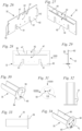
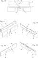
- the Fig. 21 to 25 show the first part 31.
- the first part 31 has a base plate 81.
- the base plate 81 is flat in the embodiment.
- the sleeves 58 with the stiffening webs 48 are arranged on the base plate 81, in particular welded.
- the supports 40 are fixed to the base plate 81.
- the base plate 81 has the fixing openings 44 and the recesses 41.
- the second part 32 is essentially made up of a base plate 82 on which the support web 50 is arranged. This is particularly evident in the Fig. 26 to 29 visible, which show the second part 32.
- the base plate 82 has the openings 42 for fixing to a formwork, the recesses 61 for receiving the side cheeks 18 and the Recesses 47 for the tensile force transmitting elements 9.
- the base plate 82 has two through openings 62 for the fixing bolts 45.
- the Fig. 30 to 33 show an adjustment sleeve 35.
- the adjustment sleeve 35 has the web 37 which projects into the slot 36 of the sleeve 58 ( Fig. 5 ).
- the adaptation sleeve 35 has a front plate 64 which can be used to limit the insertion depth and which in particular serves as a marking 65 for indicating a size, in particular the intended diameter of the insertable, tensile force-transmitting element.
- the adaptation sleeve 35 has a passage opening 59 which has an inner diameter di.
- Fig. 34 an adaptation sleeve 35 for a tensile force transmitting element 9 of a different size is shown, the front side 64 of which bears a different marking 65'.
- the adaptation sleeve 35 of Fig. 34 has a through-opening 60.
- the inner diameter d 2 of the through-opening 60 is larger than the inner diameter di of the through-opening 59 of the adapter sleeve 35 of the Fig. 30 to 35
- the through-openings 59 and 60 are arranged eccentrically to the outer circumference of the adaptation sleeves 35.
- the through-openings 59 and 60 are open on one long side, in particular on the side that is at the top in the installed position.
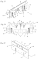
- the Fig. 35 to 46 show a further embodiment of a positioning device 26.
- the same reference numerals designate corresponding elements as in the previous figures, to the description of which reference is made here.
- the positioning device 26 has a first part 31 and a second part 32.
- the base plate 82 of the second part 32 is flat.
- the base plate 81 of the first part 31 is angled.
- the positioning device 26 is intended for a design in which the tensile force-transmitting elements 9 and 10 of the structural parts 2 and 3 are connected to one another on the first structural part 2.
- the connecting plate 11 ( Fig. 1 ) on the first longitudinal side 6 of an insulating body.
- the positioning device 26 from the Fig. 35 ff has openings 57 in the first part 31 through which fastening bolts 66 can be inserted, which are intended for connection to the connecting plate 11.
- the first part 31 is therefore in the embodiment according to Fig. 35 fixed to the connecting plate 11 and not directly connected to the first tensile force transmitting elements 9.
- Fig. 37 the connecting plate 11 is shown schematically.
- the first part 31 has several openings 57 for the fastening bolts 66.
- three openings 57 and three fastening bolts 66 are provided.
- Fastening nuts 67 are provided for fixing the fastening bolts 66.
- Fastening nuts to be screwed onto the other ends of the fastening bolts 66 are not shown.
- the other ends of the fastening bolts 66 are each screwed into a recess body with an internal thread.
- the recess bodies form in particular the recesses 15 ( Fig. 1 and 2 ). The recess bodies are removed from the first structural part 2 after the first structural part 2 has been manufactured and can in particular be reused.
- the first part 31 has the fixing openings 44, as Fig. 30
- the second part 32 has the support area 34.
- the openings 57 form the first support area 33.
- Fig. 35 to 37 the positioning device 26 is shown in a position 55 of the first part 31, in which the distance a 2 between the support areas 33 and 34 is minimal.
- Fig. 42 shows the positioning device 26 at a maximum distance a 3 of the support areas 34 and 33.
- both the first part 31 and the second part 32 have openings 42 for fixing to a formwork.
- laterally bent sections of the base plate 81 are provided on the first part 31, which have the openings 42.
- the Fig. 51 and 52 show an alternative design for a first part 31 and a second part 32. Instead of the fixing openings 44, an elongated hole 74 is provided in the first part 31.
- the parts 31 and 32 have positioning elevations 70 and positioning recesses 71 on their flat sides facing each other.
- the positioning elevations 70 and the positioning recesses 71 are designed in the manner of an intermeshing rectangular toothing.
- the grid dimension x is in Fig. 51
- Each positioning elevation 70 can engage in an associated positioning recess 71 of the other part 31, 32 and thus determine the position of the parts relative to one another.
- the second part 32 has two openings 62 through which fixing bolts 45 can protrude.
- the distance between the lowest and the highest position is determined by the length of the slot 74 and the distance between the through openings 62.
- Fixing bolts 45 (not shown) (see Fig. 9 ) determine the lateral position of the parts 31 and 32 relative to one another with the elongated hole 74.
- the support area 33 can be formed at openings 57 in the first part 31 or, as in the previous embodiment, at corresponding sleeves 58.
- the Fig. 53 to 55 show another alternative embodiment of a positioning device 29.
- the design largely corresponds to that of the embodiment from the Figures 9 to 29 .
- the support 40 which can be used, for example, as a support for a spirit level for aligning the positioning device 26, is formed by a bent section of the first part 31. This results in simple manufacture.
- the recess 41 in the first part 31 is so large that it extends over both recesses 61 of the second part 32. Accordingly, only one recess 41 is provided in the first part 31.
- a different design of the edition 40 can also be advantageous.
- the design of the positioning devices 26 of the individual embodiments is exemplary in terms of the way in which the relative positions are determined and the design of the elements.
- the individual design features can be combined with one another in any way in order to obtain further advantageous embodiments.
- positioning elevations 70 and positioning depressions 71 can also be provided in the first two embodiments.
- the base plates 81 and 82 of the parts 31 and 32 are flat and plate-shaped or sheet-shaped in all embodiments.
- the base plates 81 and 82 can be flat or angled.
- the base plates 81, 82 have a thickness d which is in particular at least 3 mm, in particular at least 5 mm, in particular at least 8 mm.
- the thickness d of the base body 81 is shown by way of example in Fig. 24 and the thickness d of the base body 82 is shown as an example in Fig. 29 marked.
- the first tensile force-transmitting elements 9 and the first compressive force-transmitting elements 19 of the connecting device 1 are first arranged in a formwork for producing the first structural part 2.
- the two parts 31 and 32 of the positioning device 26 are fixed in the desired position relative to one another.
- the positioning device 26 is arranged on the first tensile force-transmitting elements 9 and the first compressive force-transmitting elements 19, for example directly or via one or more adaptation sleeves 35 or via a connecting plate 11.
- the positioning device 26 is placed in particular on the support surface 23 of the support angle 17. It can then be provided to position and secure disks 21 on the support surface 23 to secure the position. Alternatively, it can be provided that the second part 32 of the positioning device 26 is screwed tightly to the support angle 17. Another type of securing of the positioning device 26 to the connecting device 1 can also be provided.
- the first structural part 2 is then cast. After the first structural part 2 has partially or completely hardened, the positioning device 26 is removed.
- the nuts 43 are advantageously loosened.
- a positioning device 26 according to Fig. 5 The second traction force transmitting elements 10 are in particular connected to a connecting plate 11, as in Fig. 1
- the fastening nuts 67 are loosened from the fastening bolts 66 and the fastening bolts 66 can be unscrewed from recess bodies.
- a positioning device 26 in particular a positioning device 26 according to Fig. 35
- the first tensile force transmitting elements 9 are connected in particular to a connecting plate 11 and the second tensile force transmitting elements 10 have an external thread for fixing to the connecting plate 11 via nuts.
- the discs 21 can be additionally removed or the positioning device 26 can be detached from the support bracket 17.
- the positioning device 26 is removed from the first structural part 2.
- the second structural part 3 is then fixed to the first tensile force transmitting elements 9 and the first compressive force transmitting elements 19.
- the second structural part 3 is in particular already completely manufactured. When manufactured from concrete, the second structural part is in particular already completely cast and partially or completely hardened.
- connecting devices 1 can be provided for fixing a second structural part 3.
- the supports 40 also serve in particular to align several positioning devices 26 with one another.
Landscapes
- Engineering & Computer Science (AREA)
- Architecture (AREA)
- Civil Engineering (AREA)
- Structural Engineering (AREA)
- Physics & Mathematics (AREA)
- Electromagnetism (AREA)
- Connection Of Plates (AREA)
- Insertion Pins And Rivets (AREA)
- Length Measuring Devices With Unspecified Measuring Means (AREA)
Applications Claiming Priority (1)
| Application Number | Priority Date | Filing Date | Title |
|---|---|---|---|
| DE202023103836.0U DE202023103836U1 (de) | 2023-07-10 | 2023-07-10 | Positioniervorrichtung |
Publications (1)
| Publication Number | Publication Date |
|---|---|
| EP4491815A1 true EP4491815A1 (fr) | 2025-01-15 |
Family
ID=88414582
Family Applications (1)
| Application Number | Title | Priority Date | Filing Date |
|---|---|---|---|
| EP24176170.9A Pending EP4491815A1 (fr) | 2023-07-10 | 2024-05-16 | Dispositif de positionnement et procédé de fixation d'une deuxième partie de construction sur une première partie de construction |
Country Status (2)
| Country | Link |
|---|---|
| EP (1) | EP4491815A1 (fr) |
| DE (1) | DE202023103836U1 (fr) |
Citations (4)
| Publication number | Priority date | Publication date | Assignee | Title |
|---|---|---|---|---|
| WO2017086777A1 (fr) | 2015-11-16 | 2017-05-26 | T&R Engineering B.V. | Bâtiment et balcon |
| DE102019118363A1 (de) * | 2019-07-08 | 2021-01-14 | Max Frank Gmbh & Co. Kg | Anordnung zum Verbinden eines Bauwerkteils mit einem dem Bauwerkteil vorgelagerten Stahl-Außenteil |
| DE202022103165U1 (de) * | 2022-06-03 | 2022-09-19 | Leviat GmbH | Einrichtung zur nachträglichen kraftübertragenden Anbindung eines zweiten lastaufnehmenden Bauwerksteils an ein erstes lastaufnehmendes Bauwerksteil und Bauwerk mit einer solchen Einrichtung |
| US20220316201A1 (en) * | 2021-04-01 | 2022-10-06 | Leviat GmbH | Device for Thermally Insulating, Force-Transmitting Retrofitting of a Second Load-Bearing Construction Element to a First Load-Bearing Construction Element and Structure with Such a Device |
-
2023
- 2023-07-10 DE DE202023103836.0U patent/DE202023103836U1/de active Active
-
2024
- 2024-05-16 EP EP24176170.9A patent/EP4491815A1/fr active Pending
Patent Citations (4)
| Publication number | Priority date | Publication date | Assignee | Title |
|---|---|---|---|---|
| WO2017086777A1 (fr) | 2015-11-16 | 2017-05-26 | T&R Engineering B.V. | Bâtiment et balcon |
| DE102019118363A1 (de) * | 2019-07-08 | 2021-01-14 | Max Frank Gmbh & Co. Kg | Anordnung zum Verbinden eines Bauwerkteils mit einem dem Bauwerkteil vorgelagerten Stahl-Außenteil |
| US20220316201A1 (en) * | 2021-04-01 | 2022-10-06 | Leviat GmbH | Device for Thermally Insulating, Force-Transmitting Retrofitting of a Second Load-Bearing Construction Element to a First Load-Bearing Construction Element and Structure with Such a Device |
| DE202022103165U1 (de) * | 2022-06-03 | 2022-09-19 | Leviat GmbH | Einrichtung zur nachträglichen kraftübertragenden Anbindung eines zweiten lastaufnehmenden Bauwerksteils an ein erstes lastaufnehmendes Bauwerksteil und Bauwerk mit einer solchen Einrichtung |
Also Published As
| Publication number | Publication date |
|---|---|
| DE202023103836U1 (de) | 2023-10-04 |
Similar Documents
| Publication | Publication Date | Title |
|---|---|---|
| DE2521426A1 (de) | Sollbruchvorrichtung zur halterung eines pfostens | |
| EP4036338B1 (fr) | Dispositif de raccordement ultérieur à isolation thermique et à transfert de force d'une seconde partie d'ouvrage supportant la charge à une première partie d'ouvrage supportant la charge et ouvrage doté d'un tel dispositif | |
| EP4286618B1 (fr) | Dispositif de liaison ultérieure d'une deuxième partie de construction recevant une charge à une première partie de construction recevant une charge et construction dotée d'un tel dispositif | |
| DE1903129B2 (de) | Vorrichtung zum Anschließen eines Trägers an eine Betonstütze | |
| EP2333163A1 (fr) | Structure offshore | |
| EP4538481A1 (fr) | Dispositif pour la fixation de protections contre les chutes à des échafaudages | |
| EP4063588B1 (fr) | Composant de liaison | |
| DE102016217793A1 (de) | Vorrichtung zur Verbindung einer Rammpfahlgründung mit einem Tragwerk und Verfahren zum Herstellen einer solchen Verbindung | |
| DE2402054C2 (de) | Vorrichtung zum Festspannen von Werkstücken auf einer Aufspannplatte | |
| DE19514685C2 (de) | Anordnung von mehreren Pfahlschuhen | |
| DE19907781A1 (de) | Formvorrichtung zur Herstellung vorgespannter Stahlbeton-Deckenplatten | |
| DE69006308T2 (de) | Stütz- und Verankerungsvorrichtung für vorgefertigte, insbesondere aus Beton oder ähnlichem hergestellte Gebäudeteile. | |
| EP4491815A1 (fr) | Dispositif de positionnement et procédé de fixation d'une deuxième partie de construction sur une première partie de construction | |
| EP4050171B1 (fr) | Structure de support et son procédé de fabrication | |
| EP1063361B1 (fr) | Gabarit de montage et procédé de montage d'un élément préfabriqué sur une partie de bâtiment | |
| EP0161634A2 (fr) | Poussard en particulier applicable aux travaux de blindage, p.e. blindage de tranchée | |
| CH719422A2 (de) | Verbindungseinrichtung für Tragelemente vorzugsweise für ein Traggerüst. | |
| DE202006009860U1 (de) | Aussteifungsstruktur und Befestigungselement zur Aussteifung einer Stützen aufweisenden Unterstellung einer Deckenschalung | |
| EP3348742B1 (fr) | Dispositif destiné à supporter une plaque de façade sur une structure portante | |
| DE29612053U1 (de) | Bewehrungsvorrichtung | |
| DE112011103102T5 (de) | Einbaurahmen und -verfahren | |
| EP4692490A1 (fr) | Dispositif pour la fixation de dispositifs antichute sur des échafaudages | |
| EP4361376A1 (fr) | Support de tuyau pour fixer au moins un tuyau et procédé de fabrication du support de tuyau | |
| CH695905A5 (de) | Abstand- und Distanzhalter. | |
| EP4299861A1 (fr) | Dispositif et procédé de renforcement ultérieur d'un composant doté d'au moins une zone de discontinuité |
Legal Events
| Date | Code | Title | Description |
|---|---|---|---|
| PUAI | Public reference made under article 153(3) epc to a published international application that has entered the european phase |
Free format text: ORIGINAL CODE: 0009012 |
|
| STAA | Information on the status of an ep patent application or granted ep patent |
Free format text: STATUS: THE APPLICATION HAS BEEN PUBLISHED |
|
| AK | Designated contracting states |
Kind code of ref document: A1 Designated state(s): AL AT BE BG CH CY CZ DE DK EE ES FI FR GB GR HR HU IE IS IT LI LT LU LV MC ME MK MT NL NO PL PT RO RS SE SI SK SM TR |
|
| STAA | Information on the status of an ep patent application or granted ep patent |
Free format text: STATUS: REQUEST FOR EXAMINATION WAS MADE |
|
| 17P | Request for examination filed |
Effective date: 20250505 |