EP4491824A1 - Verbindungselement für bauelemente - Google Patents
Verbindungselement für bauelemente Download PDFInfo
- Publication number
- EP4491824A1 EP4491824A1 EP24180667.8A EP24180667A EP4491824A1 EP 4491824 A1 EP4491824 A1 EP 4491824A1 EP 24180667 A EP24180667 A EP 24180667A EP 4491824 A1 EP4491824 A1 EP 4491824A1
- Authority
- EP
- European Patent Office
- Prior art keywords
- connection element
- bundle
- fibers
- bundle fibers
- forming
- Prior art date
- Legal status (The legal status is an assumption and is not a legal conclusion. Google has not performed a legal analysis and makes no representation as to the accuracy of the status listed.)
- Pending
Links
Images


Classifications
-
- E—FIXED CONSTRUCTIONS
- E04—BUILDING
- E04C—STRUCTURAL ELEMENTS; BUILDING MATERIALS
- E04C5/00—Reinforcing elements, e.g. for concrete; Auxiliary elements therefor
- E04C5/07—Reinforcing elements of material other than metal, e.g. of glass, of plastics, or not exclusively made of metal
-
- E—FIXED CONSTRUCTIONS
- E04—BUILDING
- E04G—SCAFFOLDING; FORMS; SHUTTERING; BUILDING IMPLEMENTS OR AIDS, OR THEIR USE; HANDLING BUILDING MATERIALS ON THE SITE; REPAIRING, BREAKING-UP OR OTHER WORK ON EXISTING BUILDINGS
- E04G23/00—Working measures on existing buildings
- E04G23/02—Repairing, e.g. filling cracks; Restoring; Altering; Enlarging
- E04G23/0218—Increasing or restoring the load-bearing capacity of building construction elements
- E04G2023/0251—Increasing or restoring the load-bearing capacity of building construction elements by using fiber reinforced plastic elements
- E04G2023/0262—Devices specifically adapted for anchoring the fiber reinforced plastic elements, e.g. to avoid peeling off
Definitions
- connection elements for construction elements, e.g. concrete elements, walls, ceilings, stairs, chimneys.
- Such connection elements are also referred to as anchorages or open end connectors and are used for example as a structural strengthening, to transfer and distribute forces, to interconnect construction elements or to repair concrete walls.
- connection elements are used to prevent breaking or cracking of walls and/or especially stairs due to earthquakes or other forces under which walls and/or stairs crack and endanger human lives.
- connection element wherein the connection element is made of a composite material comprising a fiber bundle and a matrix material. Fibers of a fiber bundle are hereinafter referred to as "bundle fibers".
- the connection element further comprises a solid section and a flexible section wherein the fibers of the fiber bundle - the bundle fibers - are impregnated with the matrix material within the solid section such that they are interconnected and form a monolithic structure.
- the fiber bundle consists of loose "virgin fibers" within the flexible section which means that the bundle fibers have not been impregnated with matrix material within the flexible section and are not interconnected with each other in any way.
- the person skilled in the art commonly refers to "virgin fibers” also as “dry fibers”.
- connection element When used in the building industry, usually the solid section of the connection element is arranged in a drilled hole of a wall and the dry fibers of the flexible section which protrude out of this hole are manually spread on the wall in a more or less uniform distribution around the hole.
- dry fibers are usually very prone to breakage, many of the fibers break during this manual process.
- the connection element is glued to the wall by filling the cavity of the hole and attaching the dry fibers to the surface of the wall with an adhesive.
- the material used as matrix material of the connection element is also used as adhesive to glue the connection element to the wall. This process is laborious and in the end the dry fibers are often unevenly distributed on the wall, cross each other, are bent or the fibers can even break as described above. This results in a decreased performance of the connection element, especially in transferring and distributing forces.
- connection element and a method to install the same which have the advantages of an increased performance in transferring and distributing forces and of an easy and fast installation.
- connection element comprising the features of claim 1.
- a connection element for construction elements has a fiber bundle comprising several bundle fibers, a matrix material, at least one solid section and at least one flexible section, wherein the fiber bundle is impregnated with the matrix material within the solid section to form a monolithic structure.
- the bundle fibers within the meaning of this patent application are the fibers which form part of the fiber bundle.
- a construction element can be any element used in the building industry, e.g. masonry walls, concrete elements, stairs, concrete walls or brick walls.
- the matrix material can be a polymer, e.g.
- the person skilled in the art refers to a fiber bundle being impregnated with a matrix material also as fiber reinforced plastic (FRP).
- the solid section can for example be produced by impregnating a section of the fiber bundle with the matrix material and spirally winding a yarn around the already impregnated fiber bundle to consolidate the fiber bundle.
- the bundle fibers of the connection element are attached to a flexible forming element within the flexible section such that the bundle fibers adapt to the form of the forming element.
- the attachment is irreversible.
- the connection element is usually handled by a worker with gloves to place the flexible section on a surface of a construction element.
- the bundle fibers are pre-oriented relative to each other. In other words, the bundle fibers are interconnected by the forming element. In consequence, the bundle fibers are not free.
- the flexibility of the bundle fibers is limited by the flexibility of the forming element because the bundle fibers are attached to the forming element.
- the forming element limits the flexibility of the bundle fibers within the flexible section of the connection element, the bundle fibers can be applied in a more uniform way by the worker because the comparatively fine bundle fibers are already pre-oriented by the forming element and only the comparatively coarse forming element has to be placed properly by the worker.
- the connection element can be installed in a much shorter application time than comparable connection elements known from the state of the art because all the bundle fibers can be positioned in one simple step by the correct orientation of the forming element during the installation of the connection element.
- the limited flexibility of the forming element also prevents the bundle fibers from being bent excessively during the installation of the connection element. Thus, damages to the bundle fibers are avoided.
- the bundle fibers are oriented within the flexible section in a direction radially away from the solid section and spread uniformly in a flat, circular or pitch-circular spread area around the solid section of the connection element.
- the spread area is the area which is covered by the bundle fibers.
- the connection element is suitable to be transported and handled by a worker as a single piece product.
- the size of the forming element is adapted to the size of the spread area, which is covered by the bundle fibers within the flexible section, such that the forming element has a size being at most 50 % bigger than the spread area of the bundle fibers. Most preferably, however, the size of the forming element is at most 20 % bigger than the spread area.
- the size of the forming element substantially equals the spread area.
- the forming element can also have a smaller size than the spread area of the bundle fibers.
- a connection element as described above is still transportable and workable very good. If the forming element is much bigger than defined above, the connection element is not suitable to be sold as a prefabricated product which can be installed and handled as a whole by a worker on a construction site.
- At least one of the bundle fibers is a carbon fiber, glass fiber, aramid fiber, mineral fiber, natural fiber or hybrid fiber.
- the fiber bundle can of course comprise bundle fibers of different kinds, e.g. one carbon fiber and one glass fiber or one natural fiber and one aramid fiber or any other combination of the above listed kinds of bundle fibers.
- Mineral fibers are anorganic fibers like basalt fibers, ceramic fibers or asbestos fibers.
- Natural fibers can be for example flax fibers, hemp fibers, bamboo fibers, abaca fibers (which is also known as "Manila hemp") or cellulosic fibers.
- Hybrid fibers are fibers comprising at least two different materials.
- hybrid fibers can comprise a core made from a first material (e.g. a first thermoplastic material) and a shell made from a second material (e.g. a second thermoplastic material) wherein the shell surrounds the core.
- first material e.g. a first thermoplastic material
- second material e.g. a second thermoplastic material
- All of the aforementioned fibers have very good properties which lead to an increased performance in transferring and distributing forces. However, the best improvements can be achieved with glass fibers, carbon fibers and/or aramid fibers.
- the bundle fibers are attached to the forming element by sewing and/or adhesion.
- sewing can be performed by a standard sewing needle or sewing machine needle.
- the sewing can also be performed by a special sewing machine needle adapted to perform sewing only from one side of the forming element.
- the attachment by adhesion can be performed by the application of an adhesive e.g. by gluing, impregnating and/or hot melting.
- the layer of adhesive applied on the forming element and the bundle fibers is comparatively thin, so that the forming element and the bundle fibers remain flexible up to a certain degree within the flexible section.
- a thin layer of adhesive material provides a sufficiently strong connection between the bundle fibers and the forming element.
- adhesive or the materials listed above as matrix material can be used.
- hot melting the forming element and/or the bundle fibers at least partially comprise a thermoplastic and/or a thermosetting material.
- the bundle fibers are attached to the forming element in an attachment area which is spaced apart from the end of the bundle fibers by at most 35%, preferably by at most 30%, of the length of the fibers within the flexible section.
- the fibers are connected to the forming element close to the end of the bundle fibers.
- the bundle fibers are enclosed between two forming elements within the flexible section.
- the orientation of the bundle fibers between the forming elements is even more stable.
- the bundle fibers are spread more uniformly after the installation of the connection element.
- Further improvements in the uniformity of fiber distribution can be achieved by enclosing the bundle fibers between even more forming elements.
- the fibers can be enclosed between three forming elements wherein two forming elements are arranged on a first side of the bundle fibers and one forming element on a second opposing side.
- the bundle fibers can be enclosed between four forming elements wherein two forming elements are arranged on each side of the bundle fibers.
- Such a configuration leads to an decreased flexibility of the flexible section.
- the processability can be optimized in this way just by adding or removing forming elements during the production of the connection elements.
- the forming element is flat. This means, the forming element extends substantially in a plane and/or has a plane surface.
- a flat forming element can for example be a textile or a foil.
- a flat forming element is beneficial for the use of the connection element on walls or any other plane surfaces of construction elements because the flexible section of the connection element can be easily adapted to the wall or surface without building any noticeable protrusions.
- the connection element can be installed very fast in such a configuration and the force distribution by the bundle fibers is improved.
- a forming element having a circular, triangular, square, rectangular, trapezoidal or bow-tie contour can have an effect on how the forces transmitted by the connection element are distributed as the contour can have an influence on the orientation of the bundle fibers within the flexible section and the bundle fibers have a major impact on the force distribution.
- a circular forming element and correspondingly spread bundle fibers lead to an uniform distribution of forces in a circular area around the hole in which the connection element is installed.
- a triangular forming element and correspondingly spread bundle fibers can for example be used at corners of a wall or stair to distribute forces away from the corners.
- a bow-tie forming element can distribute the forces into two different main directions which is useful to improve the load distribution of more complex connections between construction elements.
- a connection element with a bow-tie forming element can advantageously be used to connect two construction elements, e.g. stairs or two walls.
- Shapes with small deviations to the above listed contours are still possible and shall be included within the terms circular, triangular, square, rectangular, trapezoidal and bow-tie.
- shape of a triangular forming element can deviate from a strict triangular shape such that one side of the triangular contour is arcuate.
- a contour with such small deviations shall still be seen as a triangular shape within the meaning of this patent application.
- the contour of the forming element equals the spread area in which the bundle fibers are spread
- the contour of the forming element and the spread area can also have different contours.
- the bundle fibers can be spread in a substantially circular spread area whereas the forming element has a rectangular contour.
- the forming element has a through hole being at least as big as the cross section of the fiber bundle, wherein the fiber bundle passes through the through hole.
- This measure helps to prevent the fibers from being bent too much in the transition area between the solid section and the flexible section to avoid an uneven surface when the connection element is applied to a wall.
- the attachment of the bundle fibers to the forming element and the distribution of forces can be improved in this way.
- the production of the connection element is simplified as the fiber bundle can be positioned relatively to the forming element during the production by the through hole.
- the fiber bundle in connection with the through hole gives guidance to the forming element. In this way, the fiber bundle and the forming element are already correctly positioned relative to each other even if the bundle fibers are not yet attached to the forming element during production.
- the fiber bundle is positioned within the through hole such that the transition area between the solid section and the flexible section of the connection element is very close to the through hole. More preferably, the through hole is spaced apart from the solid section at most 10 mm. Most preferably however, the through hole is spaced apart from the solid section at most 30 mm. In this way the flexibility of the connection element within the transition area of the connection element can be improved which is beneficial if the connection element is installed in a hole of a building element like a concrete wall.
- Such a connector has a higher flexibility in the area of the opening of a drilled hole in the wall which enhances a good force distribution within the bundle fibers and prevents damages to the bundle fibers during installation.
- the forming element comprises several openings which have a size of 4 mm 2 to 1000 mm 2 , but preferably, however, 25 mm 2 to 400 mm 2 .
- a connection element comprising such a configuration has excellent properties with regard to permeability of adhesives and the processability of the connection element during the installation process. Therefore, such a connection element can be attached to a building element very good by the application of an adhesive on the bundle fibers and the building element because the adhesive can be applied easily through such big openings of the forming element.
- the flexible section of such a connection element can be adapted to the surface of a construction element very easy and the load distribution is improved.
- the forming element is a textile.
- a textile is a substantially planar or flat product comprising a yarn and can be produced manually or by mechanical manufacture.
- the yarn can be a filament like a monofilament or a multifilament, a fiber, a natural fiber, a synthetic fiber, a staple fiber, a filament yarn or a staple fiber yarn.
- Typical manufacturing processes for the production of a textile are for example weaving, weft knitting, warp knitting, felting, hydroentangling or sewing.
- a yarn can be arranged as a forming element in a way that the yarn is in contact with at least two of the bundle fibers, preferably however with each of the bundle fibers.
- the textile can preferably be an interconnecting yarn or a woven textile.
- a forming element can comprise several interconnecting yarns.
- the forming element can comprise several parallelly arranged interconnecting yarns.
- the at least two forming elements can both comprise parallelly arranged interconnecting yarns, wherein the interconnecting yarns of the different forming elements are arranged in an angle relative to each other such that the two interconnecting yarns of the forming elements build a lattice-like structure when they are combined.
- a lattice-like structure gives a good support to the bundle fibers and protects the bundle fibers from being bent.
- a textile grid can be a grid made from fiber reinforced plastic (FRP) like carbon fiber reinforced plastic (CFRP) or glass fiber reinforced plastic (GFRP).
- FRP fiber reinforced plastic
- CFRP carbon fiber reinforced plastic
- GFRP glass fiber reinforced plastic
- the textile preferably comprises yarns which cross each other in crossing points, wherein the yarns of the textile are interlinked in the crossing points.
- the textile has an increased stiffness due to the interlinked yarns which improves the pre-orientation of the bundle fibers and prevents the bundle fibers from being bent excessively during the installation of the connection element. Therefore, the bundle fibers tend less to break during installation and are oriented properly after installation. This enhances a uniform force distribution by the installed connection element.
- Yarns can be interlinked by adhesion or mechanically (e.g. by weaving, knitting, sewing, knotting).
- the forming element is an adhesive web.
- An adhesive web can be a nonwoven which preferably comprises thermoplastic yarns, a thermoplastic coating and/or a thermosetting coating.
- the bundle fibers are attached to the adhesive web by heating the adhesive web.
- thermoplastic yarns or a thermoplastic coating the thermoplastic material is heated up to or above its melting point and cooled down afterwards to attach the bundle fibers to the adhesive web.
- thermosetting coating the thermosetting material is preferably activated by heating to attach the bundle fibers to the adhesive web.
- the adhesive web is a hotmelt adhesive web. Hotmelt adhesive webs are also referred to as thermoadhesive webs.
- the forming element is a scrim.
- a scrim is a lattice-like textile or fabric formed by yarns.
- a scrim accordingly has openings which can be from a rather big size to enhance the permeability for adhesives or other fluids.
- the scrim can be a woven net.
- the scrim has certain advantages due to the structure of the scrim with its openings. Due to the high permeability which is achieved with the openings, the scrim can easily be sewn or glued through these openings. In other words, the bundle fibers can easily be attached to the scrim because of the lattice-like structure of the scrim.
- the processability of the connection element can be improved by using a scrim as forming element.
- connection element comprising at least two flexible sections which are spaced apart from each other by the solid section.
- the solid section is arranged between the two flexible sections.
- each of the two flexible sections is attached to one of the two opposite ends of the solid section.
- Such a connection element can be used to interconnect three or more construction elements. For example, two different construction elements can be interconnected with one wall by using just one connection element.
- a construction element suitable for being used to construct buildings can preferably be reinforced with a connection element as specified above. Due to the uniform distribution of the bundle fibers of the connection element and the reduced error susceptibility during installation of the connection element, such a construction element has a higher resilience to external forces which result for example from natural disasters like earthquakes or floods.
- connection element comprising any kind of combination of the features described above can preferably be installed on a construction element in a method comprising the following steps:
- the bundle fibers 4 are attached to a forming element 5 such that the bundle fibers 4 adapt to the form of the forming element 5.
- the forming element 5 is a flat nonwoven web having a circular contour and comprising a thermoplastic yarn 9.
- Such a nonwoven web is also referred to as adhesive web 23.
- the adhesive web 23 is drawn schematically as a group of randomly oriented yarns 9.
- the bundle fibers 4 are attached to the adhesive web 23 by placing the bundle fibers 4 on the adhesive web 23 and heating the adhesive web 23 such that the thermoplastic yarn 9 of the adhesive web 23 melts and impregnates the bundle fibers 4 which are in contact with the adhesive web 23. In this way the bundle fibers 4 are irreversibly attached to the adhesive web 23.
- the bundle fibers 4 can only be detached by heating the adhesive web 23 again or by tearing up the connection between the bundle fibers 4 and the adhesive web 23. However, the bundle fibers 4 will stay impregnated with thermoplastic material in both cases.
- the adhesive web 23 is arranged substantially flat with the bundle fibers 4 being attached to the top surface of the adhesive web 23.
- the bundle fibers 4 are more or less uniformly distributed and orientated in a radial direction of the circular contoured adhesive web 23 in order to achieve a uniform force distribution with the connection element 1.
- Figure 2 shows the same embodiment of the connection element 1 as fig. 1 . However, in fig. 2 the flexible section 3 is fold away from the solid section 2.
- the bundle fibers 4 remain in an ordered configuration within the flexible section 3 because their flexibility is limited by the flexibility of the whole forming element 5.
- the adhesive web 23 has a through hole 8 in the middle which is bigger than the cross section of the fiber bundle.
- the fiber bundle passes through this through hole 8 which helps to align the adhesive web 23 in its correct position relative to the fiber bundle during the manufacture of the connection element 1.
- the attachment of the bundle fibers 4 to the forming element 5 and the distribution of forces can be improved in this way. Surprisingly, even the resilience of the connection between the bundle fibers 4 and the forming element 5 to tensile load is increased.
- Figure 3 shows a second embodiment of the connection element 1. It differs from the first embodiment in that the forming element 5 consists of interconnecting yarns 24.
- the bundle fibers 4 are oriented in a direction radially away from the solid section 2 and distributed in a flat circular spread area 22 around the solid section 2 of the connection element 1.
- each of the two interconnecting yarns 24 is connected to each of the bundle fibers 4 to build the flexible section 3.
- the interconnecting yarns 24 can be attached to the bundle fibers 4 by automated fiber placement (also known as advanced fiber placement). Due to this possible automation of the production process, this embodiment of the connection element 1 can be produced very cheap.
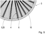
- the figures 4 to 6 show a third embodiment of the connection element 1 wherein the forming element 5 is a woven textile 25 having a circular contour.
- the structure of the woven textile 25, however, is only shown in the detail view of the connection element 1 in figure 5 for a better clarity of the drawings.
- the configuration is very similar to the configuration of the first embodiment.
- the bundle fibers 4 are attached to the woven textile 25 by sewing.
- a seam 10 that builds a stable connection between the bundle fibers 4 and the woven textile 25 is made by sewing.
- the seam 10 defines an attachment area in which the bundle fibers 4 are attached to the woven textile 25 and which is spaced apart from the end 6 of the bundle fibers 4 by less than 20% of the length 7 of the bundle fibers 4 within the flexible section 3.
- FIG. 1 shows a detail view of the flexible section 3 of the third embodiment.
- Figure 6 shows another view of the third embodiment of the connection element 1.
- the woven textile 25 has a through hole 8 in the middle and the fiber bundle passes through this through hole 8.
- the through hole 8 is placed in a transition area 11 in which the flexible section 3 adjoins the solid section 2.
- FIG. 7 shows a fourth embodiment of the connection element 1.
- the connection element 1 has substantially the same features as the connection element 1 according to the first embodiment.
- the forming element 5 is a scrim 26 instead of an adhesive web.
- the scrim 26 has a high permeability for adhesives which enhances the ease of installation of the connection element 1 when used to reinforce construction elements 12.
- the scrim 26 used as forming element 5 for the connection element 1 of fig. 7 is shown in Figure 8 in a detail view before being applied to the bundle fibers 4.
- the scrim 26 is a flat textile comprising several yarns 9 wherein the yarns 9 are oriented in three different directions and wherein in each of these directions several yarns 9 are arranged in parallel in rather big distances of 5 to 25 mm between the yarns 9.
- the yarns 9 of different directions cross each other in crossing points 19 and are interconnected in these crossing points 19. In this way openings 20 are formed between the crossing points 19 and the respective crossing yarns 9. Due to these very coarse openings 20 the scrim has a high permeability and the connection element 1 can be attached to a construction element like a wall very good by the application of an adhesive 16. Nevertheless, the scrim 26 provides for a stable orientation of the bundle fibers 4 during the installation of the connection element 1 which improves the distribution of forces after the installation.
- Figure 9 shows a connection element 1 with a forming element 5 which has a triangular shape.
- the bundle fibers 4 are attached to the triangular forming element 5 and are spread uniformly over the entire surface of the forming element 5 such that the whole forming element 5 is covered by the bundle fibers 4 in a substantially uniform way. Therefore, the contour of the forming element 5 substantially equals the spread area 22 of the bundle fibers 4.
- the shape of the forming element 5 is described as triangular, its shape can deviate from a strict triangular shape.
- one side of the triangular contour can be arcuate like its shown in fig. 9 .
- a contour with such small deviations shall still be seen as a triangular shape within the meaning of this patent application.
- Figure 10 shows a connection element 1 having a square shaped forming element 5.
- the bundle fibers 4 are spread in a substantial uniform way over the entire forming element 5.
- the connection element 1 thus guarantees a uniform distribution of forces in its operating state.
- Figure 11 shows a connection element 1 with a forming element 5 having a bow-tie shape.
- This configuration is substantially similar to the configuration shown in fig. 9 with the triangular forming element 5.
- a second triangular forming element 5 is added to build a forming element 5 having a bow-tie shape.
- the bow-tie shaped forming element 5 comprises two triangular shaped sections which are arranged relative to each other such that their contour is mirrored at their tips.
- Such a bow-tie shaped forming element 5 and distribution of the bundle fibers 4 is useful to achieve the distribution of forces in two opposing main directions.
- Figure 12 shows a connection element 1 comprising two flexible sections 3 which are spaced apart from each other by the solid section 2.
- the solid section 2 is arranged between the flexible sections 3 and each of the flexible sections 3 adjoins the solid section 2 at different opposing ends of the solid section 2.
- Such a connection element 1 can for example be used to connect two walls which are arranged next to each other like a sandwich wall.
- each of the forming elements 5 has a triangular shape.
- the forming elements 5 could also have other shapes.
- Figures 13 and 14 show another embodiment of the connection element 1.
- Figure 13 shows an exploded view of the connection element 1 which is indicated with two arrows, each of which is arranged between one of the forming elements 5 and the bundle fibers 4.
- Figure 14 shows the same embodiment in a perspective view with the forming elements 5 being in their correct positions, not in an exploded view.
- the forming element 5 and the spread area 22, in which the fibers are spread have substantially the same contour.
- the embodiment shown in the figures 13 and 14 illustrates that the forming elements 5 and the spread area 22 can also have different contours.
- the bundle fibers 4 are spread in a circular spread area 22 and the forming element 5 has a triangular shape.
- each of the bundle fibers 4 has the same length and each of the bundle fibers 4 extends out of the solid section 2 at the same point, arranging the bundle fibers 4 in a circular spread area 22 around this point of the solid section 2 is the easiest way to distribute the bundle fibers 4 uniformly.
- the contour of the forming elements 5, however, is to be cut out of a semi-finished product like a textile to produce the connection element 1. With common cutting tools it is easier to cut a straight edge than an arcuate contour like a circle. Thus, it is easier to cut triangular forming elements 5 like its shown in figs. 13 and 14 or forming elements 5 having any other contour with straight edges than cutting forming elements 5 with a circular contour. Therefore, the connection element 1 as shown in figs.
- the bundle fibers 4 are arranged between two forming elements 5 to build the flexible section 3 of the connection element 1.
- the two forming elements 5 are attached to the bundle fibers 4 on opposing flat sides of the flexible section 3.
- the bundle fibers 4 are protected between the forming elements 5 from both sides which helps to avoid damages to the bundle fibers 4 during production and application of the connection element 1.
- One of the forming elements 5 has a through hole 8 through which the fiber bundle passes. During production of the connection element 1 the fiber bundle passing through the through hole 8 gives guidance to the forming element 5 which helps to position the forming element 5 correctly on the bundle fibers 4 within the flexible section 3.
- Figures 15 and 16 show another embodiment of the connection element 1.
- Figure 15 shows an exploded view of the connection element 1 which is indicated with two arrows, each of which is arranged between one of the forming elements 5 and the bundle fibers 4.
- Figure 16 shows the same embodiment like figure 15 in a perspective view with the forming elements 5 being in their correct positions. The embodiment shown, however, differs from that one shown in the figures 14 and 15 in that each of the two forming elements 5 comprises of several parallelly arranged interconnecting yarns 24.
- the interconnecting yarns 24 of the different forming elements 5, however, are arranged relative to each other in an angle 15 such that the interconnecting yarns 24 of the two different forming elements 5 cross each other.
- connection element 1 can be produced by attaching the two forming elements 5 one after the other to the bundle fibers 4.
- the interconnecting yarns 24 of the first forming element 5 can be applied parallelly one after the other to the bundle fibers 4.
- the interconnecting yarns 24 of the second forming element 5 can be applied one after the other to the bundle fibers 4.
- the two forming elements 5 are attached to the bundle fibers 4 on opposing flat sides of the flexible section 3 to enclose the bundle fibers 4 from both sides and protect them from being excessively bent during production, transportation and application of the connection element 1.
- FIG. 17 illustrates a method to install a connection element 1 to a construction element 12.
- Figure 17 illustrates a first step in which a drilled hole 13 is drilled into the construction element 12 by a worker using a drilling machine 14. Afterwards, as shown in figure 18 , the drilled hole 13 is filled with an adhesive 16.
- the adhesive 16 can be applied with a cartridge gun 17. Some adhesive 16 is also applied around the drilled hole 13 on the surface of the construction element 12 as illustrated in fig. 19 .
- the connection element 1 is then inserted into the drilled hole 13. At the end of this step the flexible section 3 of the connection element 1 hangs loosely outside the drilled hole 13.
- the flexible section 3 is adapted to the surface of the construction element 12.
- the flexible section 3 is first adapted by softly pressing the flexible section 3 by hand on the surface onto which the adhesive 16 is already applied (see fig. 20 ).
- the bundle fibers 4 do not have to be placed and spread separately in the desired orientation. Instead, the orientation of the bundle fibers 4 is already given by their connection to the forming element 5.
- the small amount of adhesive 16 helps to fix the flexible section 3 to the surface such that it can be properly attached and adapted to the surface afterwards by applying more adhesive 16 to the flexible section 3 and the surface of the construction element 12. As illustrated in fig. 21 , this step can be performed by using a hand-held roller 18.
- Figure 22 shows the connection element 1 installed on the construction element 12 (e.g. a concrete wall).
- the flexible section 3 is adapted to the surface of the construction element 12 and attached to it by adhesion.
- the flexible section 3 extends in a flat circular area around the drilled hole 13 (which is hidden by the flexible section 3 in fig. 22 ).
- the forces transmitted by the connection element 1 are distributed to the construction element 12 in all directions around the drilled hole 13.
- Connection element 2 Solid section 3 Flexible section 4 Bundle fiber 5 Forming element 6 End of the bundle fibers (4) 7 Length of the bundle fibers (4) 8 Through hole in the forming element (5) 9 Yarn 10 Seam 11 Transition area 12 Construction element 13 Drilled hole 14 Drilling machine 15 Angle 16 Adhesive 17 Cartridge gun 18 Roller 19 Crossing point 20 Opening 22 Spread area 23 Adhesive web 24 Interconnecting yarn 25 Woven textile 26 Scrim
Landscapes
- Engineering & Computer Science (AREA)
- Architecture (AREA)
- Civil Engineering (AREA)
- Structural Engineering (AREA)
- Chemical & Material Sciences (AREA)
- Chemical Kinetics & Catalysis (AREA)
- Electrochemistry (AREA)
- Mechanical Engineering (AREA)
- Nonwoven Fabrics (AREA)
Priority Applications (1)
| Application Number | Priority Date | Filing Date | Title |
|---|---|---|---|
| EP24180667.8A EP4491824A1 (de) | 2024-06-07 | 2024-06-07 | Verbindungselement für bauelemente |
Applications Claiming Priority (1)
| Application Number | Priority Date | Filing Date | Title |
|---|---|---|---|
| EP24180667.8A EP4491824A1 (de) | 2024-06-07 | 2024-06-07 | Verbindungselement für bauelemente |
Publications (1)
| Publication Number | Publication Date |
|---|---|
| EP4491824A1 true EP4491824A1 (de) | 2025-01-15 |
Family
ID=91465327
Family Applications (1)
| Application Number | Title | Priority Date | Filing Date |
|---|---|---|---|
| EP24180667.8A Pending EP4491824A1 (de) | 2024-06-07 | 2024-06-07 | Verbindungselement für bauelemente |
Country Status (1)
| Country | Link |
|---|---|
| EP (1) | EP4491824A1 (de) |
Citations (4)
| Publication number | Priority date | Publication date | Assignee | Title |
|---|---|---|---|---|
| JP2003161002A (ja) * | 2001-11-26 | 2003-06-06 | Shimizu Corp | 定着用アンカー |
| US20060124813A1 (en) * | 2002-11-13 | 2006-06-15 | Francois Robert | Anchoring device for fixing elements of a particular type on a flat surface |
| US20120110940A1 (en) * | 2010-11-04 | 2012-05-10 | Garland Industries, Inc. | Method and apparatus for repairing concrete |
| WO2021124192A1 (en) | 2019-12-18 | 2021-06-24 | Fibre Net Holding S.R.L. | Connection element, method for manufacturing a connection element and related installation kit |
-
2024
- 2024-06-07 EP EP24180667.8A patent/EP4491824A1/de active Pending
Patent Citations (4)
| Publication number | Priority date | Publication date | Assignee | Title |
|---|---|---|---|---|
| JP2003161002A (ja) * | 2001-11-26 | 2003-06-06 | Shimizu Corp | 定着用アンカー |
| US20060124813A1 (en) * | 2002-11-13 | 2006-06-15 | Francois Robert | Anchoring device for fixing elements of a particular type on a flat surface |
| US20120110940A1 (en) * | 2010-11-04 | 2012-05-10 | Garland Industries, Inc. | Method and apparatus for repairing concrete |
| WO2021124192A1 (en) | 2019-12-18 | 2021-06-24 | Fibre Net Holding S.R.L. | Connection element, method for manufacturing a connection element and related installation kit |
Similar Documents
| Publication | Publication Date | Title |
|---|---|---|
| CA2760974C (en) | Fiber composite material and method for production thereof | |
| EP2941515B1 (de) | Fassadenbekleidungselement mit textilbewehrung und haltern und verfahren zu dessen erzeugung | |
| DK2874802T3 (en) | UNIFORM REINFORCEMENT AND PROCEDURE FOR MANUFACTURING UNIVERSAL REINFORCEMENT | |
| CA2303259C (en) | New and useful improvements in fiber-reinforced composite materials structures and methods of making the same | |
| JP7191330B2 (ja) | 結束具及び結束方法 | |
| HU217312B (hu) | Erősített faszerkezeti elem | |
| HUE027065T2 (en) | Textile reinforced concrete building block | |
| US20100029154A1 (en) | Composite reinforcement or geotextile product and its manufacturing process | |
| CN1860016B (zh) | 无卷曲可浸入增强织物及由其制成的复合增强材料 | |
| JP6022186B2 (ja) | 筋材 | |
| JP3530956B2 (ja) | 複合強化原糸を用いた複合材料及びその製造法並びに構造体 | |
| EP4491824A1 (de) | Verbindungselement für bauelemente | |
| US20230332407A1 (en) | Mesh made of a composite material | |
| JP3099656B2 (ja) | 一方向性強化繊維複合基材及びその製造方法 | |
| JP2003513174A (ja) | シート状の織物材料 | |
| JP6199440B2 (ja) | 高強力繊維線材及び該高強力繊維線材を有してなる複合材 | |
| JP2010024620A (ja) | 炭素繊維アンカーの接着構造およびその形成方法 | |
| JP6839898B2 (ja) | 繊維集成材及び繊維集成材の製造方法 | |
| JP7454363B2 (ja) | コンクリート構造物におけるコンクリート部材のせん断補強方法及びせん断補強構造 | |
| JP4813803B2 (ja) | 繊維強化シート | |
| JP6705958B1 (ja) | 繊維ロッド結束具及び繊維ロッド結束方法 | |
| CZ20021257A3 (cs) | Netkaná mříľka pouľitelná jako výztuha | |
| JP7412991B2 (ja) | コンクリート構造物の曲げ補強方法 | |
| JP2000212295A (ja) | 熱融着性を施した強化繊維 | |
| US20210069995A1 (en) | Fiber reinforced materials with improved fatigue performance |
Legal Events
| Date | Code | Title | Description |
|---|---|---|---|
| PUAI | Public reference made under article 153(3) epc to a published international application that has entered the european phase |
Free format text: ORIGINAL CODE: 0009012 |
|
| STAA | Information on the status of an ep patent application or granted ep patent |
Free format text: STATUS: THE APPLICATION HAS BEEN PUBLISHED |
|
| AK | Designated contracting states |
Kind code of ref document: A1 Designated state(s): AL AT BE BG CH CY CZ DE DK EE ES FI FR GB GR HR HU IE IS IT LI LT LU LV MC ME MK MT NL NO PL PT RO RS SE SI SK SM TR |
|
| RIN1 | Information on inventor provided before grant (corrected) |
Inventor name: BILIC, BARBARA Inventor name: PETRUNIC, SRECKO |
|
| STAA | Information on the status of an ep patent application or granted ep patent |
Free format text: STATUS: REQUEST FOR EXAMINATION WAS MADE |
|
| 17P | Request for examination filed |
Effective date: 20250715 |