EP4491896A1 - Guide linéaire - Google Patents
Guide linéaire Download PDFInfo
- Publication number
- EP4491896A1 EP4491896A1 EP23766992.4A EP23766992A EP4491896A1 EP 4491896 A1 EP4491896 A1 EP 4491896A1 EP 23766992 A EP23766992 A EP 23766992A EP 4491896 A1 EP4491896 A1 EP 4491896A1
- Authority
- EP
- European Patent Office
- Prior art keywords
- lubricant
- guide
- path
- direction changing
- paths
- Prior art date
- Legal status (The legal status is an assumption and is not a legal conclusion. Google has not performed a legal analysis and makes no representation as to the accuracy of the status listed.)
- Pending
Links
Images


Classifications
-
- F—MECHANICAL ENGINEERING; LIGHTING; HEATING; WEAPONS; BLASTING
- F16—ENGINEERING ELEMENTS AND UNITS; GENERAL MEASURES FOR PRODUCING AND MAINTAINING EFFECTIVE FUNCTIONING OF MACHINES OR INSTALLATIONS; THERMAL INSULATION IN GENERAL
- F16N—LUBRICATING
- F16N9/00—Arrangements for supplying oil or unspecified lubricant from a moving reservoir or the equivalent
- F16N9/04—Arrangements for supplying oil or unspecified lubricant from a moving reservoir or the equivalent with reservoir on or in a reciprocating, rocking, or swinging member
-
- F—MECHANICAL ENGINEERING; LIGHTING; HEATING; WEAPONS; BLASTING
- F16—ENGINEERING ELEMENTS AND UNITS; GENERAL MEASURES FOR PRODUCING AND MAINTAINING EFFECTIVE FUNCTIONING OF MACHINES OR INSTALLATIONS; THERMAL INSULATION IN GENERAL
- F16C—SHAFTS; FLEXIBLE SHAFTS; ELEMENTS OR CRANKSHAFT MECHANISMS; ROTARY BODIES OTHER THAN GEARING ELEMENTS; BEARINGS
- F16C29/00—Bearings for parts moving only linearly
- F16C29/04—Ball or roller bearings
- F16C29/06—Ball or roller bearings in which the rolling bodies circulate partly without carrying load
- F16C29/0633—Ball or roller bearings in which the rolling bodies circulate partly without carrying load with a bearing body defining a U-shaped carriage, i.e. surrounding a guide rail or track on three sides
- F16C29/0652—Ball or roller bearings in which the rolling bodies circulate partly without carrying load with a bearing body defining a U-shaped carriage, i.e. surrounding a guide rail or track on three sides whereby the return paths are at least partly defined by separate parts, e.g. covers attached to the legs of the main body of the U-shaped carriage
- F16C29/0654—Ball or roller bearings in which the rolling bodies circulate partly without carrying load with a bearing body defining a U-shaped carriage, i.e. surrounding a guide rail or track on three sides whereby the return paths are at least partly defined by separate parts, e.g. covers attached to the legs of the main body of the U-shaped carriage with balls
-
- F—MECHANICAL ENGINEERING; LIGHTING; HEATING; WEAPONS; BLASTING
- F16—ENGINEERING ELEMENTS AND UNITS; GENERAL MEASURES FOR PRODUCING AND MAINTAINING EFFECTIVE FUNCTIONING OF MACHINES OR INSTALLATIONS; THERMAL INSULATION IN GENERAL
- F16C—SHAFTS; FLEXIBLE SHAFTS; ELEMENTS OR CRANKSHAFT MECHANISMS; ROTARY BODIES OTHER THAN GEARING ELEMENTS; BEARINGS
- F16C33/00—Parts of bearings; Special methods for making bearings or parts thereof
- F16C33/30—Parts of ball or roller bearings
- F16C33/66—Special parts or details in view of lubrication
- F16C33/6637—Special parts or details in view of lubrication with liquid lubricant
- F16C33/6659—Details of supply of the liquid to the bearing, e.g. passages or nozzles
Definitions
- the present invention relates to a linear guide, and more particularly to a linear guide enabling lubricant to be evenly supplied to a plurality of direction changing paths in an end cap.
- a linear guide (linear motion guide) includes a guide rail extending in an axial direction, and a slider extending over the guide rail in a manner of being movable relative to the guide rail, and the slider relatively moves in the axial direction on the guide rail via a plurality of rolling elements (balls or rollers) circulating between rolling element rolling grooves (rolling element circulation paths) respectively formed in the guide rail and the slider.
- rolling elements balls or rollers
- rolling element rolling grooves rolling element circulation paths
- the lubricant used for the linear guide is classified into two types including grease and oil (lubricating oil).
- the grease and the oil are selectively used according to a use environment of the linear guide.
- the oil is used in an environment in which a coolant of a machine tool or the like is scattered, and the grease is used in other high-speed moving parts, vacuum environments, and clean room specifications.
- the grease and the oil have different ease of flow when flowing through the lubricant supply path. Therefore, conflicting cross-sectional areas are required for the lubricating oil supply path when supplying grease and when supplying oil.
- the lubricant is evenly supplied (flows separately) to a plurality of direction changing paths (rolling element U-turn paths) defined between an end cap and a return guide.
- Patent Literature 1 proposes a motion guide device (linear guide) in which an attachment that narrows a lubricant supply path of an end plate (end cap) when oil is used is disposed in the lubricant supply path such that a failure such as leakage does not occur regardless of the type of lubricant.
- the lubricant supply path for oil can be suitably secured using the attachment provided in the lubricant supply path. Further, in two upper and lower direction changing paths formed between a return piece part (return guide) and the end plate, the lubricant can be evenly distributed by a branching portion of the lubricant supply path connected to the direction changing paths.
- Patent Literature 2 proposes a lubricating device for an infinite linear motion guide unit (linear guide) in which oil supply paths (lubricant supply paths) are formed to have substantially the same oil path length from a nipple hole bored in a side surface of a side plate (end cap) to respective direction changing paths provided symmetrically from both sides.
- an amount of lubricant supplied from the nipple hole to the both direction changing paths is made uniform, thereby enabling the lubricant to be evenly distributed to the left and right direction changing paths.
- a method of enabling the lubricant to be evenly distributed to the upper and lower direction changing paths when there are plurality of direction changing paths is not disclosed.
- the oil may pass at it is through a lubricant supply hole that communicates with the upper direction changing path when the oil flows, and the lubricant may concentrate in the lower direction changing path. If there is such a circulation path in which a supply amount of the lubricant is insufficient, there is a risk of causing a failure such as burning of the infinite linear motion guide unit (linear guide).
- the present invention has been made in view of the above-described problems, and an object thereof is to provide a linear guide enabling lubricant to be evenly supplied to upper and lower direction changing paths regardless of a type of the lubricant.
- a linear guide includes: a guide rail; a slider main body of a slider including a plurality of rolling element raceway grooves and rolling element return paths and slidably engaged with the guide rail so as to straddle the guide rail; and a pair of end caps each including a plurality of direction changing paths and respectively attached to end portions of the slider main body in an axial direction of the slider main body,
- linear guide of the present invention it is possible to provide a linear guide enabling the lubricant to be evenly supplied to the upper and lower direction changing paths regardless of a type of the lubricant.
- an upper-lower direction (H) and a width direction (W) of a slider respectively represent directions in a state where the slider is assembled to a guide rail arranged with a longitudinal direction (D) being horizontal, and the width direction (W) of the slider is a direction perpendicular to the longitudinal direction of the guide rail and the upper-lower direction (H) of the slider, and is also referred to as a left-right direction (see FIG. 1 ).
- the longitudinal direction (D) of the slider is also referred to as an axial direction.
- a linear guide 1 includes a linear guide rail 3 and a slider 20 that is assembled to straddle the guide rail 3, slidably engaged with the guide rail 3 via a plurality of rolling elements (balls) (not shown), and has a C-shaped cross section.
- the guide rail 3 is made of metal, and on both side surfaces in the width direction, rail-side raceway surfaces 5 extending in the axial direction are formed in three rows on each side, and a total of six rows.
- the guide rail 3 has a plurality of rail attachment holes 4 each penetrating in a height direction of the guide rail 3, and rail fixing bolts (not shown) for fixing the guide rail 3 to an attachment surface (not shown) are inserted in the rail attachment holes 4.
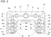
- the slider 20 includes a slider main body 21 having sleeve portions on both left and right sides of the guide rail 3, a pair of end caps 30, 30 attached to both end portions of the slider main body 21 in the front-rear direction (axial direction), return guides 40, 40 incorporated into the end caps 30, 30 in pairs, and a pair of side seals 60, 60 for sealing gaps between the guide rail 3 and the end caps 30, 30.
- the slider main body 21 includes a plurality of (three in the present embodiment) slider-side raceway surfaces and rolling element return paths (not shown) on each of left and right sides.
- the slider-side raceway surfaces are formed on inner surfaces of the two sleeve portions of the slider main body 21, face the rail-side raceway surfaces 5 of the guide rail 3, and three load rolling paths are formed by the rail-side raceway surfaces 5 and the slider-side raceway surfaces.
- the rolling element return paths are formed by three holes penetrating thick portions of the two sleeve portions in the axial direction of the guide rail 3.
- driven-object-fixing-screw insertion holes 25 through each of which a bolt for fixing a driven object such as a table to the slider 20 is inserted.
- the end cap 30 of the first embodiment is, for example, an injection molded product of a synthetic resin material, and is formed to have a C-shaped cross section as the slider main body 21.
- a plurality of attachment-screw insertion holes 34 are formed, and the end cap 30 and the side seal 60 are fastened to an end portion (facing surface) in the front-rear direction of the slider main body 21 by attachment screws 35 inserted through the attachment-screw insertion holes 34.
- the return guide 40 is assembled on a contact surface 31a side facing the end portion in the front-rear direction of the slider main body 21.
- the return guide 40 is fitted into a recess portion formed in a contact surface 31a of the end cap 30, thus defining a plurality of (three in the present embodiment) direction changing paths 26a, 26b, and 26c between the return guide 40 and the end cap 30.
- the direction changing paths 26a, 26b, and 26c are respectively connected to the three load rolling paths and the rolling element return paths of the slider main body 21.
- the load rolling paths, the rolling element return paths, and the direction changing paths 26a, 26b, and 26c form rolling element circulation paths.
- Many rolling elements (balls) are rollably loaded in the rolling element circulation paths, and the slider 20 can relatively move along the axial direction on the guide rail 3 via the rolling elements that endlessly circulate while rolling in the rolling element circulation paths.
- a facing surface 40a of the return guide 40 facing the end portion in the front-rear direction of the slider main body 21 is provided with a lubricant path groove 42 having a semicircular cross section and communicating with the direction changing paths 26a, 26b, and 26c via a plurality of (three in the present embodiment) lubricant supply holes 44a, 44b, and 44c arranged in series along a lubricant supply direction (downward in the upper-lower direction) (see FIGS. 3Ato 3C ).
- a horizontal portion 32 of the end cap 30 is provided with a lubricant path groove 37, extending in the width direction, on a contact surface 32a side facing the end portion in the front-rear direction of the slider main body 21.
- a lubricant introduction portion 33 for introducing the lubricant from a nipple 50 into the end cap 30 is bored in a central portion of the lubricant path groove 37.
- each of the left and right sleeve portions 31 of the end cap 30 is provided with a lubricant path groove 38 extending from the lubricant path groove 37 to the lubricant path groove 42 of the return guide 40.
- a lubricant path that communicates with the lubricant introduction portion 33 and guides the lubricant to the direction changing paths 26a, 26b, and 26c, is defined between an end surface of the slider main body 21 and the lubricant path groove 37, the lubricant path groove 38, and the lubricant path groove 42 of the end cap 30.
- the slider 20 in which the end cap 30 is fixed to the end portion in the front-rear direction of the slider main body 21 is provided with the lubricant introduction portion 33 that introduces the lubricant into the end cap 30; the lubricant path that communicates with the lubricant introduction portion 33 and guides the lubricant to the direction changing paths 26a, 26b, and 26c; and the plurality of lubricant supply holes 44a, 44b, and 44c that communicate with the lubricant path and the plurality of direction changing paths 26a, 26b, and 26c, and supply the lubricant to the respective direction changing paths 26a, 26b, and 26c.
- the lubricant introduced into the end cap 30 from the nipple 50 reaches the lubricant path grooves 42 from the lubricant introduction portion 33 through the lubricant path grooves 37 and 38, and is supplied to the direction changing paths 26a, 26b, and 26c through the lubricant supply holes 44a, 44b, and 44c, respectively.
- a plurality of (two in the present embodiment) lubricant guide portions 45 are arranged in series between the three lubricant supply holes 44a, 44b, and 44c arranged in series along the lubricant supply direction (X).
- the lubricant guide portions 45 are plate-shaped weir portions protruding from the lubricant path groove 42 respectively on a downstream side of the vicinity of the lubricant supply holes 44a and 44b, in order to introduce the lubricant into the lubricant supply holes 44a and 44b on the upstream side by protruding into the lubricant path and partially restricting flow of the lubricant from an upper side to a lower side.
- the slider 20 of the linear guide 1 can prevent, by the lubricant guide portions 45 and 45 provided between the plurality of arranged lubricant supply holes 44a, 44b, and 44c, the lubricant from passing as it is through the lubricant supply holes 44a and 44b on an upstream side toward the lubricant supply holes 44b and 44c on a downstream side even when oil having a low viscosity is used as the lubricant. Therefore, the oil is easily supplied to the upper direction changing paths 26a and 26b of the end cap 30, and the lubricant path suitable for both the oil and the grease having different viscosities can be designed. Further, unlike the motion guide device of Patent Literature 1 described above, it is not necessary to use different parts such as the attachment depending on the lubricant path.
- the linear guide 1 can evenly supply the lubricant to the upper and lower direction changing paths regardless of the type of the lubricant.
- the lubricant guide portions 45 protrude from the lubricant path groove 42 on the downstream side of the vicinity of the lubricant supply holes 44a and 44b so as to be spaced apart from the lubricant supply holes 44a and 44b. Therefore, when grease having a high viscosity is used as the lubricant, the grease can be prevented from clogging between the lubricant guide portions 45 and the lubricant supply holes 44a and 44b.
- the lubricant guide portions 45 are provided to protrude from the lubricant path groove 42 on the downstream side in the vicinity of the lubricant supply holes 44a and 44b so as to be adjacent to the lubricant supply holes 44a and 44b. In this case, there is no step between the lubricant guide portions 45 and the respective lubricant supply holes 44a and 44b, and oil is more easily supplied to the lubricant supply holes 44a and 44b on the upstream side.
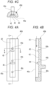
- FIGS. 4A to 4C are respectively a front view of a return guide 40A according to a second embodiment of the present invention, a cross-sectional view taken along a line C-C, and a cross-sectional view taken along a line D-D.
- two lubricant guide portions 45 and 46 are arranged in series between three lubricant supply holes 44a, 44b, and 44c arranged in series along the lubricant supply direction (X).
- the lubricant guide portions 45 and 46 are plate-shaped weir portions respectively provided on a downstream side of the vicinity of the lubricant supply holes 44a and 44b, in order to introduce the lubricant into the lubricant supply holes 44a and 44b on the upstream side by protruding into the lubricant path and partially restricting flow of the lubricant from an upper side to a lower side. Further, the lubricant guide portion 46 on the downstream side has a larger protrusion height than the lubricant guide portion 45 on the upstream side.
- the lubricant is also easily guided to the lubricant supply hole 44b disposed between the lubricant supply hole 44a on the upstream side and the lubricant supply hole 44c on the downstream side.
- the effect of evenly supplying the lubricant to the upper and lower direction changing paths 26a, 26b, and 26c in the end cap 30 can be further enhanced.
- FIGS. 5A to 5C are respectively a front view of a return guide 40B according to a third embodiment of the present invention, a cross-sectional view taken along a line E-E, and a cross-sectional view taken along a line F-F.
- two lubricant guide portions 47, 47 are arranged in series between the three lubricant supply holes 44a, 44b, and 44c arranged in series along the lubricant supply direction (X).
- the lubricant guide portions 47 are semi-cylindrical weir portions respectively provided on a downstream side of the vicinity of the lubricant supply holes 44a and 44b, in order to introduce the lubricant into the lubricant supply holes 44a and 44b on the upstream side by protruding into the lubricant path and partially restricting flow of the lubricant from an upper side to a lower side.
- the lubricant guide portion 47 has a cylindrical surface 47a coaxial with a corresponding one of the lubricant supply holes 44a and 44b adjacent thereto.
- the lubricant is efficiently guided to the lubricant supply holes 44a and 44b by the cylindrical surfaces 47a of the lubricant guide portions 47. Therefore, the lubricant is more easily supplied to the upper direction changing paths 26a and 26b. Thus, the effect of evenly supplying the lubricant to the upper and lower direction changing paths 26a, 26b, and 26c in the end cap 30 can be further enhanced.
- linear guide 1 of each of the above-described embodiments it is possible to provide a linear guide enabling the lubricant (oil or grease) to be evenly supplied to the upper and lower direction changing paths 26a, 26b, and 26c regardless of the type of the lubricant.
- the present invention is not limited to the above-described embodiments, and can be appropriately modified, improved, or the like. Further, a material, a shape, a size, the number of, an arrangement position, and the like of each component in the above-described embodiment are be freely set and are not limited as long as the present invention can be achieved.
- the end caps 30 are respectively attached to both end portions in the axial direction of the slider main body 21, but the slider of the present invention is not limited thereto.
- the end cap 30 may be attached to at least one of the end portions of the slider main body 21, and the end cap attached to the other end portion of the slider main body 21 may not include the lubricant introduction portion, the lubricant path, and the lubricant supply hole.
- lubricant guide portions 45, 46, and 47 of the above-described embodiments are plate-shaped or semi-cylindrical weir portions
- the lubricant guide portion of the present invention is not limited thereto, and it is needless to say that various forms can be adopted based on the gist of the present invention.
- cylindrical rollers may be used instead of the balls.
- the lubricant can be prevented from passing as it is through the lubricant supply holes (44a, 44b) on the upstream side toward the lubricant supply holes (44b, 44c) on a downstream side by the lubricant guide portions (45, 46, 47) provided between the plurality of arranged lubricant supply holes (44a, 44b, 44c). Therefore, the oil is easily supplied to the upper direction changing paths (26a, 26b) in the end cap (30), and the lubricant path (lubricant path grooves 37,38, 42) suitable for both the oil and the grease having different viscosities can be designed.
- the grease when grease having a high viscosity is used as the lubricant, the grease can be prevented from clogging between the lubricant guide portion (45, 46, 47) and the lubricant supply holes (44a, 44b).
- the lubricant is also easily guided to the lubricant supply hole (44b) disposed between the lubricant supply hole (44a) on the upstream side and the lubricant supply hole (44c) on the downstream side.
- the effect of evenly supplying the lubricant to the upper and lower direction changing paths (26a, 26b, 26c) in the end cap (30) can be further enhanced.
- the lubricant is efficiently guided to the lubricant supply hole (44a, 44b) by the cylindrical surface (47a) of the lubricant guide portion (47).
- the lubricant is more easily supplied to the upper direction changing paths (26a, 26b).
- the effect of evenly supplying the lubricant to the upper and lower direction changing paths (26a, 26b, 26c) in the end cap (30) can be further enhanced.
- an effect of enabling the lubricant to be evenly supplied to the upper and lower direction changing paths regardless of a type of the lubricant can be exerted.
- the present invention having the effect is useful in prevention of a failure such as burning of the linear guide.
Landscapes
- Engineering & Computer Science (AREA)
- General Engineering & Computer Science (AREA)
- Mechanical Engineering (AREA)
- Bearings For Parts Moving Linearly (AREA)
Applications Claiming Priority (2)
| Application Number | Priority Date | Filing Date | Title |
|---|---|---|---|
| JP2022037909A JP7663082B2 (ja) | 2022-03-11 | 2022-03-11 | リニアガイド |
| PCT/JP2023/009461 WO2023171816A1 (fr) | 2022-03-11 | 2023-03-10 | Guide linéaire |
Publications (2)
| Publication Number | Publication Date |
|---|---|
| EP4491896A1 true EP4491896A1 (fr) | 2025-01-15 |
| EP4491896A4 EP4491896A4 (fr) | 2025-07-02 |
Family
ID=87935468
Family Applications (1)
| Application Number | Title | Priority Date | Filing Date |
|---|---|---|---|
| EP23766992.4A Pending EP4491896A4 (fr) | 2022-03-11 | 2023-03-10 | Guide linéaire |
Country Status (4)
| Country | Link |
|---|---|
| EP (1) | EP4491896A4 (fr) |
| JP (1) | JP7663082B2 (fr) |
| CN (1) | CN118382763A (fr) |
| WO (1) | WO2023171816A1 (fr) |
Families Citing this family (1)
| Publication number | Priority date | Publication date | Assignee | Title |
|---|---|---|---|---|
| JP7540568B2 (ja) | 2022-11-02 | 2024-08-27 | 東ソー株式会社 | ゼオライト成形体 |
Family Cites Families (6)
| Publication number | Priority date | Publication date | Assignee | Title |
|---|---|---|---|---|
| DE4330772B4 (de) * | 1993-09-10 | 2013-02-14 | Robert Bosch Gmbh | Linearführungseinrichtung |
| JP2008138840A (ja) * | 2006-12-05 | 2008-06-19 | Nsk Ltd | リニアガイド装置のスライダ |
| JP4816570B2 (ja) | 2007-05-28 | 2011-11-16 | 日本精工株式会社 | 直動案内装置用エンドキャップおよび直動案内装置 |
| JP2011153669A (ja) | 2010-01-27 | 2011-08-11 | Thk Co Ltd | 運動案内装置、及びこの運動案内装置に用いられるアタッチメント |
| CN112228455B (zh) | 2019-07-15 | 2023-10-31 | Thk株式会社 | 运动引导装置以及在运动引导装置中使用的润滑路径部件 |
| DE102020210760A1 (de) | 2020-08-25 | 2022-03-03 | Te Connectivity Germany Gmbh | Stecker mit einem Lagesicherungselement mit einer Kontaktaufnahme |
-
2022
- 2022-03-11 JP JP2022037909A patent/JP7663082B2/ja active Active
-
2023
- 2023-03-10 EP EP23766992.4A patent/EP4491896A4/fr active Pending
- 2023-03-10 CN CN202380015092.8A patent/CN118382763A/zh active Pending
- 2023-03-10 WO PCT/JP2023/009461 patent/WO2023171816A1/fr not_active Ceased
Also Published As
| Publication number | Publication date |
|---|---|
| CN118382763A (zh) | 2024-07-23 |
| JP7663082B2 (ja) | 2025-04-16 |
| EP4491896A4 (fr) | 2025-07-02 |
| JP2023132534A (ja) | 2023-09-22 |
| WO2023171816A1 (fr) | 2023-09-14 |
Similar Documents
| Publication | Publication Date | Title |
|---|---|---|
| US20090304312A1 (en) | Motion guide device and attachment for motion guide device | |
| US20060023980A1 (en) | Rolling guide unit | |
| US20090196539A1 (en) | Wide-width guide carriage | |
| US7066650B2 (en) | Linear motion guide unit | |
| KR102796004B1 (ko) | 운동 안내 장치 및 운동 안내 장치에서 사용되는 윤활 경로 구성요소 | |
| EP4491896A1 (fr) | Guide linéaire | |
| US8033730B2 (en) | Linear motion guide unit with rollers | |
| KR0166992B1 (ko) | 선형 안내장치 | |
| US8662752B2 (en) | Motion guide device and method of manufacturing same | |
| US8506166B2 (en) | Linear motion guide unit | |
| US7762722B2 (en) | Linear motion guide unit | |
| US4886374A (en) | Linear guide apparatus | |
| US9194428B2 (en) | Linear motion guide unit with separators interposed between adjoining rolling elements | |
| JP4943204B2 (ja) | 案内装置とその潤滑剤導入部材及び潤滑剤供給構造 | |
| US6709158B2 (en) | Linear motion guide unit with separator between any two adjoining rollers | |
| EP4317724A1 (fr) | Guide linéaire | |
| JP4562140B2 (ja) | 繋ぎ用軌道レールを備えた直動案内ユニット | |
| KR102521772B1 (ko) | 운동 안내 장치 | |
| JP2011153669A (ja) | 運動案内装置、及びこの運動案内装置に用いられるアタッチメント | |
| US7832929B2 (en) | Linear motion guide unit | |
| JP2024119325A (ja) | リニアガイド | |
| JP2022157873A (ja) | 直動案内装置 | |
| JP2025005938A (ja) | エンドキャップおよびそれを用いた直動案内装置 | |
| US20230258232A1 (en) | Motion guidance device | |
| JP6186264B2 (ja) | 潤滑構造を備えるリニアガイド |
Legal Events
| Date | Code | Title | Description |
|---|---|---|---|
| STAA | Information on the status of an ep patent application or granted ep patent |
Free format text: STATUS: THE INTERNATIONAL PUBLICATION HAS BEEN MADE |
|
| PUAI | Public reference made under article 153(3) epc to a published international application that has entered the european phase |
Free format text: ORIGINAL CODE: 0009012 |
|
| STAA | Information on the status of an ep patent application or granted ep patent |
Free format text: STATUS: REQUEST FOR EXAMINATION WAS MADE |
|
| 17P | Request for examination filed |
Effective date: 20240611 |
|
| AK | Designated contracting states |
Kind code of ref document: A1 Designated state(s): AL AT BE BG CH CY CZ DE DK EE ES FI FR GB GR HR HU IE IS IT LI LT LU LV MC ME MK MT NL NO PL PT RO RS SE SI SK SM TR |
|
| DAV | Request for validation of the european patent (deleted) | ||
| DAX | Request for extension of the european patent (deleted) | ||
| A4 | Supplementary search report drawn up and despatched |
Effective date: 20250604 |
|
| RIC1 | Information provided on ipc code assigned before grant |
Ipc: F16C 33/66 20060101ALI20250528BHEP Ipc: F16N 9/04 20060101ALI20250528BHEP Ipc: F16C 29/06 20060101AFI20250528BHEP |
|
| GRAP | Despatch of communication of intention to grant a patent |
Free format text: ORIGINAL CODE: EPIDOSNIGR1 |
|
| STAA | Information on the status of an ep patent application or granted ep patent |
Free format text: STATUS: GRANT OF PATENT IS INTENDED |
|
| INTG | Intention to grant announced |
Effective date: 20260202 |
|
| GRAS | Grant fee paid |
Free format text: ORIGINAL CODE: EPIDOSNIGR3 |
|
| GRAA | (expected) grant |
Free format text: ORIGINAL CODE: 0009210 |
|
| STAA | Information on the status of an ep patent application or granted ep patent |
Free format text: STATUS: THE PATENT HAS BEEN GRANTED |