EP4491903A1 - Réducteur de vitesse - Google Patents
Réducteur de vitesse Download PDFInfo
- Publication number
- EP4491903A1 EP4491903A1 EP24186242.4A EP24186242A EP4491903A1 EP 4491903 A1 EP4491903 A1 EP 4491903A1 EP 24186242 A EP24186242 A EP 24186242A EP 4491903 A1 EP4491903 A1 EP 4491903A1
- Authority
- EP
- European Patent Office
- Prior art keywords
- carrier
- planetary
- gear
- speed reducer
- planetary shafts
- Prior art date
- Legal status (The legal status is an assumption and is not a legal conclusion. Google has not performed a legal analysis and makes no representation as to the accuracy of the status listed.)
- Pending
Links
Images


Classifications
-
- F—MECHANICAL ENGINEERING; LIGHTING; HEATING; WEAPONS; BLASTING
- F16—ENGINEERING ELEMENTS AND UNITS; GENERAL MEASURES FOR PRODUCING AND MAINTAINING EFFECTIVE FUNCTIONING OF MACHINES OR INSTALLATIONS; THERMAL INSULATION IN GENERAL
- F16H—GEARING
- F16H1/00—Toothed gearings for conveying rotary motion
- F16H1/28—Toothed gearings for conveying rotary motion with gears having orbital motion
-
- F—MECHANICAL ENGINEERING; LIGHTING; HEATING; WEAPONS; BLASTING
- F16—ENGINEERING ELEMENTS AND UNITS; GENERAL MEASURES FOR PRODUCING AND MAINTAINING EFFECTIVE FUNCTIONING OF MACHINES OR INSTALLATIONS; THERMAL INSULATION IN GENERAL
- F16H—GEARING
- F16H1/00—Toothed gearings for conveying rotary motion
- F16H1/28—Toothed gearings for conveying rotary motion with gears having orbital motion
- F16H1/32—Toothed gearings for conveying rotary motion with gears having orbital motion in which the central axis of the gearing lies inside the periphery of an orbital gear
-
- F—MECHANICAL ENGINEERING; LIGHTING; HEATING; WEAPONS; BLASTING
- F16—ENGINEERING ELEMENTS AND UNITS; GENERAL MEASURES FOR PRODUCING AND MAINTAINING EFFECTIVE FUNCTIONING OF MACHINES OR INSTALLATIONS; THERMAL INSULATION IN GENERAL
- F16H—GEARING
- F16H57/00—General details of gearing
- F16H57/08—General details of gearing of gearings with members having orbital motion
-
- F—MECHANICAL ENGINEERING; LIGHTING; HEATING; WEAPONS; BLASTING
- F16—ENGINEERING ELEMENTS AND UNITS; GENERAL MEASURES FOR PRODUCING AND MAINTAINING EFFECTIVE FUNCTIONING OF MACHINES OR INSTALLATIONS; THERMAL INSULATION IN GENERAL
- F16H—GEARING
- F16H57/00—General details of gearing
- F16H57/08—General details of gearing of gearings with members having orbital motion
- F16H57/082—Planet carriers
-
- F—MECHANICAL ENGINEERING; LIGHTING; HEATING; WEAPONS; BLASTING
- F16—ENGINEERING ELEMENTS AND UNITS; GENERAL MEASURES FOR PRODUCING AND MAINTAINING EFFECTIVE FUNCTIONING OF MACHINES OR INSTALLATIONS; THERMAL INSULATION IN GENERAL
- F16H—GEARING
- F16H1/00—Toothed gearings for conveying rotary motion
- F16H1/28—Toothed gearings for conveying rotary motion with gears having orbital motion
- F16H1/32—Toothed gearings for conveying rotary motion with gears having orbital motion in which the central axis of the gearing lies inside the periphery of an orbital gear
- F16H2001/327—Toothed gearings for conveying rotary motion with gears having orbital motion in which the central axis of the gearing lies inside the periphery of an orbital gear with the orbital gear having internal gear teeth
Definitions
- the column portion includes: a plurality of column bodies each disposed between two of the plurality of planetary shafts adjacent to each other in the circumferential direction; and a connecting portion connecting two of the plurality of column bodies adjacent to each other in the circumferential direction, and the connecting portion is positioned inside the plurality of planetary shafts in a radial direction of the internal gear.
- the above-described speed reducers can have a further increased rigidity.
- Fig. 1 is a schematic sectional view of a speed reducer 1.
- the speed reducer 1 is what is-called a planetary gear reducer.
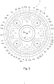
- the speed reducer 1 includes an internal gear 2 having a cylindrical shape, a carrier 3 provided rotatably relative to the internal gear 2, a sun shaft 4 arranged coaxially with a rotation axis A1 of the carrier 3, and four planetary shafts 5 arranged in the rotational direction of the carrier 3 around the rotation axis A1.
- the rotation axis A1 of the carrier 3 is referred to as the carrier axis A1.
- the direction parallel with the carrier axis A1 is referred to as the axial direction.
- the rotational direction of the carrier 3 is referred to as the circumferential direction.
- the direction orthogonal to the axial direction and the circumferential direction (the radial direction of the carrier 3) is referred to as the radial direction.
- An outer flange 6 having an annular shape and projecting outward in the radial direction is formed on an outer peripheral surface 2a of the internal gear 2.
- the outer flange 6 is used to attach the speed reducer 1 to an external device, which is not shown.
- the outer flange 6 has a plurality of bolt insertion holes 6a arranged at equal intervals in the circumferential direction.
- the speed reducer 1 is fixed to the external device by inserting bolts (not shown) into the bolt insertion holes 6a and tightening the bolts to the external device (not shown).
- An inner flange 7 having an annular shape and projecting inward in the radial direction is formed on an inner peripheral surface 2b of the internal gear 2.
- Internal teeth 7a are formed on an inner peripheral surface of the inner flange 7.
- the internal teeth 7a extend over the entire axial length of the inner flange 7.
- Main bearings 81, 82 (a first main bearing 81 and a second main bearing 82) are provided on the inner peripheral surface 2b of the internal gear 2 on axially opposite sides of the inner flange 7.
- the two main bearings 81, 82 are formed symmetrically around the inner flange 7. Therefore, the following description only mentions the first main bearing 81 of the two main bearings 81 and 82.
- Each part of the second main bearing 82 which is denoted by the same symbol as the corresponding part of the first main bearing 81, will not be described.
- the outer race 81b is integrally formed with the internal gear 2.
- the inner race 81a is integrally formed with the carrier 3.
- the internal gear 2 includes a seal retainer 8 on the opposite side to the inner flange 7 with respect to the first main bearing 81.
- the seal retainer 8 has a cylindrical shape and projects in the axial direction.
- the inner peripheral surface 8a of the seal retainer 8 receives the outer peripheral surface of a seal portion 9 with an annular shape fitted thereon.
- the seal portion 9 provides sealing between the internal gear 2 and the carrier 3.
- the two carrier plates 11 and 12 are formed symmetrically around the inner flange 7. Therefore, the following description only mentions the first carrier plate 11 of the two carrier plates 11 and 12.
- Each part of the second carrier plate 12, which is denoted by the same symbol as the corresponding part of the first carrier plate 11, will not be described.
- the description of the second carrier plate 12 is limited to the differences from the first carrier plate 11.
- the plate body 13 has a through hole 13c formed in the radially middle portion thereof.
- the through hole 13c extends through the plate body 13 in the axial direction.
- the through hole 13c is coaxial with the carrier axis A1.
- a first bearing housing 15 is formed on the second carrier plate 12 side of the through hole 13c.
- the first bearing housing 15 is a circular recess, as viewed from the axial direction.
- the first bearing housing 15 is coaxial with the carrier axis A1.
- the inner diameter of the first bearing housing 15 is larger than that of the through hole 13c.
- the first bearing housing 15 receives a first bearing 17.
- the first bearing 17 is, for example, a ball bearing. However, this feature is not limitative, and various bearings such as a cylindrical roller bearing can be used as the first bearing 17.
- the first bearing 17 rotatably supports the sun shaft 4.
- the plate body 13 has four second bearing housings 16 arranged around the first bearing housing 15.
- the second bearing housings 16 are arranged at equal intervals in the circumferential direction around the carrier axis A1.
- the second bearing housings 16 are recesses formed in one side 13d of the plate body 13 on the second carrier plate 12 side.
- the second bearing housings 16 have a circular shape, as viewed from the axial direction.
- Each of the second bearing housings 16 receives a second bearing 18.
- the second bearing 18 is, for example, a ball bearing. However, this feature is not limitative, and various bearings such as a cylindrical roller bearing can be used as the second bearing 18.
- the second bearing 18 rotatably supports a planetary shaft 5.
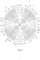
- Each of the column bodies 21 is formed in the shape of a quadrangular prism.
- the outer surface 21a of the column body 21 on the radially outer side extends along the circumferential direction.
- the two side surfaces 21b, which extend orthogonally to the outer surface 21a as viewed from the axial direction, are opposed to each other in the circumferential direction.
- Each of the connecting portions 22 is formed to connect the radially inner ends of the column bodies 21. Therefore, the connecting portion 22 is positioned radially inside the planetary shafts 5.
- the inner surface 22a of the connecting portion 22 on the radially inner side is shaped like an arc centered at the carrier axis A1.
- the outer surface 22b of the connecting portion 22 on the radially outer side is shaped like an arc to avoid the second bearing housing 16.
- the outer surface 22b of the connecting portion 22 is smoothly continuous to the side surfaces 21b of the column bodies 21.
- Each of the connecting portions 22 does not necessarily extend over the entire interval between two column bodies 21 adjacent to each other in the circumferential direction. In other words, the connecting portions 22 do not necessarily extend over the entire circumference.
- Each of the connecting portions 22 should extend from the side surface 21b of the column body 21 for a predetermined length in the circumferential direction. This will be described in detail later.
- the column bodies 21 and the connecting portions 22 project from one side 13d of the plate body 13 by the same length. Therefore, the distal end 14a of the column portion 14 is planar.
- the projecting length of the column bodies 21 and the connecting portions 22 projecting from one side 13d of the plate body 13 is hereinafter referred to as the projecting length of the column portion 14.
- first carrier plate 11 and the second carrier plate 12 are joined together by connecting the respective distal ends 14a of their column portions 14. This creates a certain amount of spacing between the plate bodies 13 of the carrier plates 11 and 12.
- the projecting length of the column portion 14 is determined so that this amount of spacing is larger than the axial length of the inner flange 7 in the internal gear 2.
- the inner flange 7 is positioned between the two plate bodies 13.
- each of the regions corresponding to the column bodies 21 has a plurality (for example, four in this embodiment) of pin holes 23.
- a pin (not shown) into each of the pin holes 23
- the second carrier plate 12 does not have a seal surface 13b, unlike the first carrier plate 11. For this reason, the axial thickness of the second carrier plate 12 is smaller than that of the first carrier plate 11.
- the sun shaft 4 is rotatably supported by the respective first bearings 17 provided on the carrier plates 11 and 12.
- the end 4a of the sun shaft 4 on the second carrier plate 12 side projects outward in the axial direction through the first bearing 17.
- a sun gear 24 and an input gear 25 are provided to be arranged in this order from the first bearing 17 side.
- the sun gear 24 is integrated with the sun shaft 4.
- the input gear 25 is fitted and fixed to the sun shaft 4.
- the input gear 25 rotates integrally with the sun shaft 4.
- the input gear 25 is meshed with a drive gear 26a of an electric motor 26, for example.
- the input gear 25 receives a motive power.
- the planetary shafts 5 are rotatably supported by the second bearings 18 provided on the carrier plates 11 and 12.
- the planetary shafts 5 rotate around the respective rotation axes A2.
- the rotation axes A2 will be hereinafter referred to as the planetary axes A2.
- the planetary axes A2 are parallel to the carrier axis A1.
- the ends 5a of the planetary shafts 5 on the second carrier plate 12 side project outward in the axial direction through the second bearings 18.
- First planetary gears 27 are fitted and fixed to these projecting portions.
- the first planetary gears 27 are meshed with the sun gear 24.
- a second planetary gear 28 is integrated with the portion of each planetary shaft 5 between the two second bearings 18.
- the second planetary gear 28 is meshed with the internal teeth 7a of the inner flange 7.
- the carrier 3 As each planetary gears 27 and 28 and planetary shaft 5 revolve, the carrier 3 is rotated relative to the internal gear 2. If the internal gear 2 is fixed to an external device (not shown), the carrier 3 serves as an output unit. Specifically, if a driven member (not shown) is attached to the carrier 3, the rotation of the drive gear 26a is decelerated and output to the driven member via the carrier 3. It is also possible that, for example, the carrier 3 is fixed to an external device, and the internal gear 2 serves as the output unit.
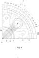
- Figs. 4 and 5 show the region in which the column portion 14 is present. Figs. 4 and 5 show only one-fourth of the circumference of the carrier 3 for convenience of explanation. As described above, the connecting portions 22 do not necessarily extend over the entire circumference. As shown in Fig. 4 , a connecting portion 22 (column portion 14) should be present at least in the region S3 between two second lines L2 parallel to the first line L1 connecting the carrier axis A1 and the planetary axis A2. The two second lines L2 are tangent to the addendum circle diameter D of the second planetary gear 28. This condition is hereinafter referred to as the first condition.
- the carrier 3 includes two carrier plates 11 and 12 and a column portion 14 connecting the two carrier plates 11 and 12. With this configuration of the carrier 3, the carrier 3 can be easily formed to satisfy at least the first condition. As a result, the rigidity of the speed reducer 1 can be easily increased. If the carrier 3 is formed to satisfy the second condition, the connecting portions 22 can be further projected in the circumferential direction compared to the first condition. Thus, the carrier 3 can be present more between the planetary shafts 5 adjacent to each other in the circumferential direction. Therefore, the carrier 3 can receive more moment load applied to the speed reducer 1. As a result, the rigidity of the speed reducer 1 can be increased securely.
- the carrier 3 is constituted by the two carrier plates 11 and 12 that overlap in the axial direction and the column portion 14 formed on each of the carrier plates 11 and 12.
- this configuration is not limitative, but the carrier 3 can have any configuration in which the sun shaft 4 and the planetary shafts 5 are supported rotatably. The requirement is that the carrier 3 is formed to satisfy the first condition or the second condition described above.
- the carrier 3 is rotatably supported by the internal gear 2.
- this configuration is not limitative, but the carrier 3 can have any configuration in which it is rotatable relative to the internal gear 2.
- the carrier 3 may be rotatably supported by a member other than the internal gear 2.
- a member formed of multiple components may be integrated into a single component, or conversely, a member formed of a single component may be divided into multiple components. Irrespective of whether or not the components are integrated, they are acceptable as long as they are configured to attain the object of the invention.
Landscapes
- Engineering & Computer Science (AREA)
- General Engineering & Computer Science (AREA)
- Mechanical Engineering (AREA)
- Retarders (AREA)
- General Details Of Gearings (AREA)
Applications Claiming Priority (1)
| Application Number | Priority Date | Filing Date | Title |
|---|---|---|---|
| JP2023114057A JP2025011755A (ja) | 2023-07-11 | 2023-07-11 | 減速機 |
Publications (1)
| Publication Number | Publication Date |
|---|---|
| EP4491903A1 true EP4491903A1 (fr) | 2025-01-15 |
Family
ID=91810185
Family Applications (1)
| Application Number | Title | Priority Date | Filing Date |
|---|---|---|---|
| EP24186242.4A Pending EP4491903A1 (fr) | 2023-07-11 | 2024-07-03 | Réducteur de vitesse |
Country Status (3)
| Country | Link |
|---|---|
| EP (1) | EP4491903A1 (fr) |
| JP (1) | JP2025011755A (fr) |
| CN (1) | CN119308975A (fr) |
Citations (3)
| Publication number | Priority date | Publication date | Assignee | Title |
|---|---|---|---|---|
| US20140274550A1 (en) * | 2011-11-01 | 2014-09-18 | Nissan Motor Co., Ltd. | Carrier structure for planetary gear set |
| EP3098477A2 (fr) * | 2015-05-26 | 2016-11-30 | The Boeing Company | Système d'engrenage planétaire et porte-satellites |
| US20170198785A1 (en) | 2014-06-02 | 2017-07-13 | Premium Stephan Hameln Zweigniederlassung Der Premium Stephan B.V. | Planetary gearbox |
-
2023
- 2023-07-11 JP JP2023114057A patent/JP2025011755A/ja active Pending
-
2024
- 2024-07-03 EP EP24186242.4A patent/EP4491903A1/fr active Pending
- 2024-07-05 CN CN202410896497.3A patent/CN119308975A/zh active Pending
Patent Citations (3)
| Publication number | Priority date | Publication date | Assignee | Title |
|---|---|---|---|---|
| US20140274550A1 (en) * | 2011-11-01 | 2014-09-18 | Nissan Motor Co., Ltd. | Carrier structure for planetary gear set |
| US20170198785A1 (en) | 2014-06-02 | 2017-07-13 | Premium Stephan Hameln Zweigniederlassung Der Premium Stephan B.V. | Planetary gearbox |
| EP3098477A2 (fr) * | 2015-05-26 | 2016-11-30 | The Boeing Company | Système d'engrenage planétaire et porte-satellites |
Also Published As
| Publication number | Publication date |
|---|---|
| CN119308975A (zh) | 2025-01-14 |
| JP2025011755A (ja) | 2025-01-24 |
Similar Documents
| Publication | Publication Date | Title |
|---|---|---|
| US8545357B2 (en) | Gear transmission | |
| US10281007B2 (en) | Speed reducer | |
| US6508737B2 (en) | Eccentric orbiting type speed reducer | |
| JP4818787B2 (ja) | 揺動内接噛合遊星歯車装置 | |
| JP5603717B2 (ja) | 揺動内接噛合型の遊星歯車装置およびその製造方法 | |
| KR101066233B1 (ko) | 감속 장치 | |
| EP0291052A2 (fr) | Système de transmission planétaire | |
| JP7186171B2 (ja) | 撓み噛合い式歯車装置 | |
| JP2008202764A (ja) | 揺動内接噛合遊星歯車装置及びその偏心体軸の製造方法 | |
| US8961361B2 (en) | Wheel drive unit | |
| KR20100097564A (ko) | 유성기어 감속기의 고정링 기어 결합구조 | |
| WO2011083698A1 (fr) | Dispositif d'engrenage planétaire du type à mise en prise intérieure oscillant | |
| TW201109549A (en) | Simple planetary gear speed reducer series | |
| JPH11210843A (ja) | 遊星歯車減速機 | |
| EP4491903A1 (fr) | Réducteur de vitesse | |
| US12297893B2 (en) | Speed reducer | |
| JP6338538B2 (ja) | 撓み噛合い式歯車装置 | |
| EP2730805B1 (fr) | Engrenage réducteur | |
| JP4897496B2 (ja) | 揺動内接噛合式の遊星歯車装置 | |
| JP7660418B2 (ja) | 軸受のインナレース、回転機器、及び、減速機 | |
| JP7472599B2 (ja) | 遊星減速機 | |
| CN105805147B (zh) | 齿轮轴 | |
| JP7624847B2 (ja) | 伝達装置 | |
| WO2020031891A1 (fr) | Dispositif formant train épicycloïdal | |
| JP7452191B2 (ja) | 車両用駆動伝達装置 |
Legal Events
| Date | Code | Title | Description |
|---|---|---|---|
| PUAI | Public reference made under article 153(3) epc to a published international application that has entered the european phase |
Free format text: ORIGINAL CODE: 0009012 |
|
| STAA | Information on the status of an ep patent application or granted ep patent |
Free format text: STATUS: REQUEST FOR EXAMINATION WAS MADE |
|
| 17P | Request for examination filed |
Effective date: 20240703 |
|
| AK | Designated contracting states |
Kind code of ref document: A1 Designated state(s): AL AT BE BG CH CY CZ DE DK EE ES FI FR GB GR HR HU IE IS IT LI LT LU LV MC ME MK MT NL NO PL PT RO RS SE SI SK SM TR |