EP4491918A1 - Vanne rotative - Google Patents
Vanne rotative Download PDFInfo
- Publication number
- EP4491918A1 EP4491918A1 EP24180998.7A EP24180998A EP4491918A1 EP 4491918 A1 EP4491918 A1 EP 4491918A1 EP 24180998 A EP24180998 A EP 24180998A EP 4491918 A1 EP4491918 A1 EP 4491918A1
- Authority
- EP
- European Patent Office
- Prior art keywords
- sealing member
- rotor
- housing
- cover
- rotary valve
- Prior art date
- Legal status (The legal status is an assumption and is not a legal conclusion. Google has not performed a legal analysis and makes no representation as to the accuracy of the status listed.)
- Pending
Links
Images



Classifications
-
- F—MECHANICAL ENGINEERING; LIGHTING; HEATING; WEAPONS; BLASTING
- F16—ENGINEERING ELEMENTS AND UNITS; GENERAL MEASURES FOR PRODUCING AND MAINTAINING EFFECTIVE FUNCTIONING OF MACHINES OR INSTALLATIONS; THERMAL INSULATION IN GENERAL
- F16K—VALVES; TAPS; COCKS; ACTUATING-FLOATS; DEVICES FOR VENTING OR AERATING
- F16K11/00—Multiple-way valves, e.g. mixing valves; Pipe fittings incorporating such valves
- F16K11/02—Multiple-way valves, e.g. mixing valves; Pipe fittings incorporating such valves with all movable sealing faces moving as one unit
- F16K11/06—Multiple-way valves, e.g. mixing valves; Pipe fittings incorporating such valves with all movable sealing faces moving as one unit comprising only sliding valves, i.e. sliding closure elements
- F16K11/072—Multiple-way valves, e.g. mixing valves; Pipe fittings incorporating such valves with all movable sealing faces moving as one unit comprising only sliding valves, i.e. sliding closure elements with pivoted closure members
- F16K11/076—Multiple-way valves, e.g. mixing valves; Pipe fittings incorporating such valves with all movable sealing faces moving as one unit comprising only sliding valves, i.e. sliding closure elements with pivoted closure members with sealing faces shaped as surfaces of solids of revolution
-
- F—MECHANICAL ENGINEERING; LIGHTING; HEATING; WEAPONS; BLASTING
- F16—ENGINEERING ELEMENTS AND UNITS; GENERAL MEASURES FOR PRODUCING AND MAINTAINING EFFECTIVE FUNCTIONING OF MACHINES OR INSTALLATIONS; THERMAL INSULATION IN GENERAL
- F16K—VALVES; TAPS; COCKS; ACTUATING-FLOATS; DEVICES FOR VENTING OR AERATING
- F16K5/00—Plug valves; Taps or cocks comprising only cut-off apparatus having at least one of the sealing faces shaped as a more or less complete surface of a solid of revolution, the opening and closing movement being predominantly rotary
- F16K5/04—Plug valves; Taps or cocks comprising only cut-off apparatus having at least one of the sealing faces shaped as a more or less complete surface of a solid of revolution, the opening and closing movement being predominantly rotary with plugs having cylindrical surfaces; Packings therefor
- F16K5/0407—Plug valves; Taps or cocks comprising only cut-off apparatus having at least one of the sealing faces shaped as a more or less complete surface of a solid of revolution, the opening and closing movement being predominantly rotary with plugs having cylindrical surfaces; Packings therefor with particular plug arrangements, e.g. particular shape or built-in means
-
- F—MECHANICAL ENGINEERING; LIGHTING; HEATING; WEAPONS; BLASTING
- F16—ENGINEERING ELEMENTS AND UNITS; GENERAL MEASURES FOR PRODUCING AND MAINTAINING EFFECTIVE FUNCTIONING OF MACHINES OR INSTALLATIONS; THERMAL INSULATION IN GENERAL
- F16K—VALVES; TAPS; COCKS; ACTUATING-FLOATS; DEVICES FOR VENTING OR AERATING
- F16K27/00—Construction of housing; Use of materials therefor
- F16K27/06—Construction of housing; Use of materials therefor of taps or cocks
- F16K27/065—Construction of housing; Use of materials therefor of taps or cocks with cylindrical plugs
-
- F—MECHANICAL ENGINEERING; LIGHTING; HEATING; WEAPONS; BLASTING
- F16—ENGINEERING ELEMENTS AND UNITS; GENERAL MEASURES FOR PRODUCING AND MAINTAINING EFFECTIVE FUNCTIONING OF MACHINES OR INSTALLATIONS; THERMAL INSULATION IN GENERAL
- F16K—VALVES; TAPS; COCKS; ACTUATING-FLOATS; DEVICES FOR VENTING OR AERATING
- F16K5/00—Plug valves; Taps or cocks comprising only cut-off apparatus having at least one of the sealing faces shaped as a more or less complete surface of a solid of revolution, the opening and closing movement being predominantly rotary
- F16K5/04—Plug valves; Taps or cocks comprising only cut-off apparatus having at least one of the sealing faces shaped as a more or less complete surface of a solid of revolution, the opening and closing movement being predominantly rotary with plugs having cylindrical surfaces; Packings therefor
- F16K5/0457—Packings
- F16K5/0471—Packings between housing and plug
-
- F—MECHANICAL ENGINEERING; LIGHTING; HEATING; WEAPONS; BLASTING
- F16—ENGINEERING ELEMENTS AND UNITS; GENERAL MEASURES FOR PRODUCING AND MAINTAINING EFFECTIVE FUNCTIONING OF MACHINES OR INSTALLATIONS; THERMAL INSULATION IN GENERAL
- F16K—VALVES; TAPS; COCKS; ACTUATING-FLOATS; DEVICES FOR VENTING OR AERATING
- F16K5/00—Plug valves; Taps or cocks comprising only cut-off apparatus having at least one of the sealing faces shaped as a more or less complete surface of a solid of revolution, the opening and closing movement being predominantly rotary
- F16K5/08—Details
-
- F—MECHANICAL ENGINEERING; LIGHTING; HEATING; WEAPONS; BLASTING
- F16—ENGINEERING ELEMENTS AND UNITS; GENERAL MEASURES FOR PRODUCING AND MAINTAINING EFFECTIVE FUNCTIONING OF MACHINES OR INSTALLATIONS; THERMAL INSULATION IN GENERAL
- F16K—VALVES; TAPS; COCKS; ACTUATING-FLOATS; DEVICES FOR VENTING OR AERATING
- F16K11/00—Multiple-way valves, e.g. mixing valves; Pipe fittings incorporating such valves
- F16K11/02—Multiple-way valves, e.g. mixing valves; Pipe fittings incorporating such valves with all movable sealing faces moving as one unit
- F16K11/08—Multiple-way valves, e.g. mixing valves; Pipe fittings incorporating such valves with all movable sealing faces moving as one unit comprising only taps or cocks
- F16K11/085—Multiple-way valves, e.g. mixing valves; Pipe fittings incorporating such valves with all movable sealing faces moving as one unit comprising only taps or cocks with cylindrical plug
Definitions
- This disclosure generally relates to a rotary valve.
- the cylinder valve includes a valve guide having an opening on a side surface, and a valve element having an opening on a side surface and being inserted in the valve guide, and the cylinder valve is configured in such a way as to control circulation of a fluid by adjusting a position of the opening of the valve element and a position of the opening of the valve guide.
- a recessed portion is formed on an outer peripheral side surface of the opening. A sealing member is put into the recessed portion and a pressing member is attached to an opening of the sealing member.
- the sealing member in a configuration in which the sealing member is put into the recessed portion and the opening of the sealing member is pressed by the pressing member, the sealing member is free from a risk of being deformed by pressure applied by a fluid.
- a size of the valve may increase.
- the sealing member may be deformed by pressure applied by a fluid.
- a rotary valve includes: a rotor that controls circulation of a fluid by rotating about an axis; a sealing member having an opening through which the fluid flows, the sealing member being disposed on a radially outer side of the rotor; a housing that accommodates the rotor and the sealing member; and a cover placed on the housing in such a way as to face against the rotor and the sealing member in an axial direction along the axis, and the cover includes a pressing portion that presses the sealing member when the cover is placed on the housing.
- the cover including the pressing portion is placed on the housing in such a way as to face against the sealing member in the axial direction and the pressing portion of the cover presses the sealing member when the cover is placed on the housing, and therefore, deformation of the sealing member in the axial direction can be prevented.
- the sealing member is pressed by the pressing portion formed in the cover that occludes an inside of the housing, and therefore, a size of the rotary valve may be reduced compared with a configuration in which a recessed portion for accommodating the sealing member is formed in the housing or the rotor and the sealing member is pressed by a separate member.
- this configuration allows deformation of the sealing member to be suppressed and leakage of the fluid to be prevented while reducing the size.
- FIG. 1 is a sectional view (longitudinal sectional view) taken along an axis AX of a rotary valve 100 according to an embodiment.
- the rotary valve 100 is used, for example, for controlling a fluid F that is circulated in a device to be cooled such as a battery or a motor installed in a vehicle such as an automobile.
- the fluid F is cooling water such as a long-life coolant (LLC).
- the fluid F may be an insulating oil of paraffin-base or the like, or a refrigerant made of hydrofluorocarbon (HFC), hydrofluoroolefin (HFO), or the like.
- the rotary valve 100 includes a housing 1, a rotor 2 accommodated in the housing 1, a sealing member 3 disposed between the housing 1 and the rotor 2, a cover 4 placed on the housing 1 in such a way as to cover the rotor 2 and the sealing member 3, and an actuator 5 connected to the rotor 2.
- the rotary valve 100 is attached to a manifold (not illustrated) with an internal flow path formed therein through which the fluid F is circulated by a driving force of a pump (not illustrated).
- the actuator 5 transmits torque to the rotor 2.
- the rotor 2 is rotated by the torque from the actuator 5 about the axis AX. With the rotation of the rotor 2, flow of the fluid F is controlled.
- a direction along the axis AX of the rotor 2 is referred to as an "axial direction DX", a circumferential direction of the rotor 2 as a “circumferential direction DC”, and a radial direction of the rotor 2 as a “radial direction DR.”
- the side in the axial direction DX, viewed from the rotor 2, on which the cover 4 is placed is referred to as "one side in the axial direction DX1", the opposite side thereto as “the other side in the axial direction DX2”, the side of the axis AX in the radial direction DR as a “radially inner side DR1", and the opposite side thereto as a “radially outer side DR2.”
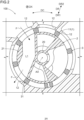
- FIG. 2 is a sectional view (transverse sectional view) of the rotary valve 100 taken along the radial direction DR. Note that FIG. 2 illustrates the housing 1, the rotor 2, and the sealing member 3 viewed from the cover 4. As illustrated in FIG. 2 , the housing 1 accommodates the rotor 2 and the sealing member 3. The housing 1 includes a housing wall 11 that defines a space in which the rotor 2 and the sealing member 3 are accommodated.
- the housing wall 11 has a circular shape when viewed along the axial direction DX.
- the housing wall 11 has a plurality of ports 12 formed therein along the circumferential direction DC.
- the ports 12 penetrate through the housing wall 11 along the radial direction DR and connect, via the internal flow path of the manifold (not illustrated), to an external flow path that is connected to a motor, a battery, or the like.
- FIG. 3 is a perspective view illustrating a structure of the rotor 2.
- the rotor 2 includes an axial portion 20 concentric with the axis AX and a cylindrical valve portion 21 that is rotatable together with the axial portion 20.
- the rotor 2 is made of a material such as a resin, and the axial portion 20 and the valve portion 21 are integrally formed.
- a valve flow path L1 through which the fluid F flows is formed in the valve portion 21, a valve flow path L1 through which the fluid F flows is formed.
- the fluid F flows through the valve flow path L1 when the rotor 2 is oriented in such a way that the valve flow path L1 and the ports 12 (see FIG. 2 ) face against each other in the radial direction DR.
- the sealing member 3 is disposed on the radially outer side DR2 of the rotor 2.
- the sealing member 3 is disposed on substantially all circumferences of the rotor 2 in the circumferential direction DC, and prevents the fluid F from leaking out of the flow path.
- the sealing member 3 is constructed of an elastically deformable member, and the sealing member 3 is compressed by the housing 1, the rotor 2, and the cover 4. Thus, leakage of the fluid F out of the flow path (flowing into other flow paths) is prevented.
- the sealing member 3 is made of rubber such as nitrile butadiene rubber (NBR), fluorine rubber (FKM), or polyurethane rubber (U).
- FIG. 4 is a perspective view illustrating a structure of the sealing member 3.
- the sealing member 3 includes a cylindrical sealing member main body 31.
- a plurality of (in the present embodiment, eight) sealing member openings 31h are formed in the sealing member main body 31.
- the plurality of sealing member openings 31h are arranged along the circumferential direction DC. Note that the plurality of sealing member openings 31h are formed at positions that are aligned with positions of the plurality of ports 12, which has been described with reference to FIG. 2 , and have shapes that match the ports 12.
- the sealing member openings 31h penetrate through the sealing member main body 31 in the radial direction DR.
- the fluid F flows into or out of the valve flow path L1 through the sealing member openings 31h when the rotor 2 is oriented in such a way that the valve flow path L1 and the ports 12 face against each other in the radial direction DR.
- the sealing member 3 also includes a plurality of ribs 32 that protrude from the sealing member main body 31 in the radial direction DR.
- the ribs 32 protrude from the sealing member main body 31 toward the radially inner side DR1 and toward the radially outer side DR2.
- the plurality of ribs 32 are individually arranged in such a way as to surround the sealing member opening 31h. More specifically, each of the ribs 32 has a plurality of circumferential ribs 34 and a plurality of axial ribs 36.
- the plurality of circumferential ribs 34 are arranged in such a way as to face against each other in the axial direction DX across the sealing member opening 31h and the circumferential ribs 34 individually extend along the circumferential direction DC (uninterruptedly formed).
- the plurality of axial ribs 36 are arranged in such a way as to face against each other in the circumferential direction DC across the sealing member opening 31h and the axial ribs 36 individually extend along the axial direction DX (uninterruptedly formed).
- the circumferential rib 34 and the axial rib 36 connect on the outside of corners of the sealing member opening 31h.
- a connected portion between the circumferential rib 34 and the axial rib 36 is referred to as a "junction area P.”
- FIG. 5 is a diagram illustrating a structure of the cover 4 (a plan view viewed along the axial direction DX). As illustrated in FIG. 5 , the cover 4 is a substantially circular plate when viewed along the axial direction DX. As illustrated in FIG. 1 , the cover 4 is placed on the housing 1 in such a way as to face against the rotor 2 and the sealing member 3 in the axial direction DX.
- the cover 4 includes a proximal portion 41 having a circular shape (disk shape) when viewed along the axial direction DX and an extension portion 42 that extends in the axial direction DX from the proximal portion 41 as a proximal end (see FIG. 1 ).
- the proximal portion 41 includes a first opposing surface 41S that faces against the rotor 2.
- a through-hole 41h that penetrates through the proximal portion 41 in the axial direction DX and into which the axial portion 20 of the rotor 2 is inserted is formed in the center.
- the extension portion 42 is tubular (cylindrical) when viewed along the axial direction DX.
- the extension portion 42 is arranged along a periphery of the proximal portion 41.
- an unillustrated helical engaging slot for example, a male thread
- an unillustrated engaged slot for example, a female thread
- the cover 4 includes a deformation suppressing portion 43 (an example of a pressing portion) that suppresses deformation of the sealing member 3 in the axial direction DX.
- the deformation suppressing portion 43 is arranged on the radially inner side DR1 of the extension portion 42.
- the deformation suppressing portion 43 includes a protrusion 431 that protrudes toward the other side in the axial direction DX2 (in the axial direction DX) from the first opposing surface 41S as a proximal end.
- FIG. 6 is a schematic diagram illustrating a structure of the rotary valve 100 in an area near the protrusion 431. Note that the extension portion 42 is omitted in FIG. 6 .
- the protrusion 431 contacts with the sealing member 3 (sealing member main body 31) when the cover 4 is fixed to the housing 1. More specifically, the protrusion 431 is designed to press the sealing member 3 toward the other side in the axial direction DX2 when the cover 4 is fixed to the housing 1, thereby causing the sealing member 3 to be elastically compressed.
- the deformation suppressing portion 43 includes a plurality of protrusions 431 (eight protrusions in the present embodiment).
- the plurality of protrusions 431 are arranged along the circumferential direction DC.
- the plurality of protrusions 431 are arranged at intervals from each other in the circumferential direction DC. In other words, the plurality of protrusions 431 are not in contact with the whole circumference of the sealing member 3 (sealing member main body 31) as illustrated in FIG. 6 , and arranged in such a way as to contact with portions of the sealing member 3 in the circumferential direction DC.
- the sealing member 3 Since the plurality of protrusions 431 are arranged in such a way as to contact with portions of the sealing member 3 in the circumferential direction DC, the sealing member 3 is only partially elastically compressed as illustrated with a long dashed double-dotted line in FIG. 6 , thereby enabling prevention of excessive elastic compression of the sealing member 3. Thus, deformation of the sealing member 3 can be suppressed.
- the protrusions 431 are arranged at positions that are aligned with positions of the sealing member openings 31h formed in the sealing member 3, which has been described with reference to FIG. 4 .
- the protrusions 431 are arranged at positions where the protrusions 431 face against the sealing member openings 31h formed in the sealing member 3 in the axial direction DX.
- the protrusions 431 are arranged at positions where the protrusions 431 overlap with the sealing member openings 31h when viewed from the axial direction DX.
- the protrusions 431 are arranged at positions where the protrusions 431 do not face against the axial ribs 36 in the axial direction DX.
- deformation (twist) of the sealing member 3 caused by deformation of the axial rib 36 can be prevented.
- the protrusion 431 is arranged at a position where the protrusion 431 overlaps with a central area 31C of the sealing member opening 31h in the circumferential direction DC (a portion including the center of the sealing member openings 31h in the circumferential direction DC) in the axial direction DX when the cover 4 is fixed to the housing 1.
- the protrusion 431 includes a second opposing surface 431S (an example of an opposing surface) that faces against the sealing member 3.
- a groove 431m is formed in the second opposing surface 431S.
- the protrusion 431 includes two concave portions 431k that are hollowed in such a way as to be closer to the first opposing surface 41S in the axial direction DX, and the groove 431m is constructed from the two concave portions 431k.
- the two concave portions 431k are arranged line-symmetrically with respect to an imaginary line L that passes through the center of the protrusion 431 serving as an axis of symmetry.
- the sealing member main body 31 subjected to pressure from the fluid F can penetrate into the concave portion 431k of the groove 431m.
- deformation of the sealing member 3 in a manner escaping the protrusion 431 (deformation outside of the protrusion 431) can be prevented. Consequently, generation of a gap between the sealing member 3 and a sealing surface (a surface of the housing 1 and/or the rotor 2 with which the sealing member 3 is in contact when the sealing member 3 is oriented in such a way as to prevent leakage of the fluid F) can be prevented.
- the sealing member 3 When the sealing member 3 is deformed, for example, by fluid pressure of the fluid F in a manner escaping the protrusion 431, the junction area P where the circumferential rib 34 and the axial rib 36 intersect is dragged and the axial rib 36 is slanted with respect to the axial direction DX, leading to deformation of the entire sealing member 3; consequently, a gap may be generated between the sealing member 3 and the sealing surface. When a gap is generated between the sealing member 3 and the sealing surface, the fluid F will leak out of the flow path.
- the concave portion 431k can absorb deformation of the sealing member 3 on one side in the axial direction DX1 (i.e., receive the deformed portion of the sealing member 3), deformation of the sealing member 3 in a manner escaping the protrusion 431 can be prevented.
- generation of a gap between the sealing member 3 and the sealing surface can be prevented, and leakage of the fluid F out of the flow path can be prevented.
- the present disclosure may be used for a rotary valve.
Landscapes
- Engineering & Computer Science (AREA)
- General Engineering & Computer Science (AREA)
- Mechanical Engineering (AREA)
- Taps Or Cocks (AREA)
- Multiple-Way Valves (AREA)
- Sliding Valves (AREA)
- Valve Housings (AREA)
Applications Claiming Priority (1)
| Application Number | Priority Date | Filing Date | Title |
|---|---|---|---|
| JP2023114657A JP2025012090A (ja) | 2023-07-12 | 2023-07-12 | ロータリバルブ |
Publications (1)
| Publication Number | Publication Date |
|---|---|
| EP4491918A1 true EP4491918A1 (fr) | 2025-01-15 |
Family
ID=91470089
Family Applications (1)
| Application Number | Title | Priority Date | Filing Date |
|---|---|---|---|
| EP24180998.7A Pending EP4491918A1 (fr) | 2023-07-12 | 2024-06-10 | Vanne rotative |
Country Status (4)
| Country | Link |
|---|---|
| US (1) | US12546402B2 (fr) |
| EP (1) | EP4491918A1 (fr) |
| JP (1) | JP2025012090A (fr) |
| CN (1) | CN119309025A (fr) |
Citations (4)
| Publication number | Priority date | Publication date | Assignee | Title |
|---|---|---|---|---|
| JP2004011813A (ja) | 2002-06-07 | 2004-01-15 | Toto Ltd | シリンダバルブ |
| US20200318750A1 (en) * | 2017-12-19 | 2020-10-08 | Halliburton Energy Services, Inc. | Enhanced design for plug valve |
| WO2022065617A1 (fr) * | 2020-09-25 | 2022-03-31 | 에스아이플로텍(주) | Vanne de fluide |
| US20220170558A1 (en) * | 2020-11-30 | 2022-06-02 | Xomox Corporation | Torque reduction valve having separate static seal and dynamic seal |
Family Cites Families (2)
| Publication number | Priority date | Publication date | Assignee | Title |
|---|---|---|---|---|
| US3584831A (en) * | 1968-02-24 | 1971-06-15 | Sempell Rhein Armaturen | Cock with elastic lining |
| WO2017059107A1 (fr) * | 2015-09-29 | 2017-04-06 | Kerr Machine Co. | Dispositifs à débit haute pression d'étanchéité |
-
2023
- 2023-07-12 JP JP2023114657A patent/JP2025012090A/ja active Pending
-
2024
- 2024-06-10 EP EP24180998.7A patent/EP4491918A1/fr active Pending
- 2024-07-01 US US18/760,511 patent/US12546402B2/en active Active
- 2024-07-11 CN CN202410926990.5A patent/CN119309025A/zh active Pending
Patent Citations (4)
| Publication number | Priority date | Publication date | Assignee | Title |
|---|---|---|---|---|
| JP2004011813A (ja) | 2002-06-07 | 2004-01-15 | Toto Ltd | シリンダバルブ |
| US20200318750A1 (en) * | 2017-12-19 | 2020-10-08 | Halliburton Energy Services, Inc. | Enhanced design for plug valve |
| WO2022065617A1 (fr) * | 2020-09-25 | 2022-03-31 | 에스아이플로텍(주) | Vanne de fluide |
| US20220170558A1 (en) * | 2020-11-30 | 2022-06-02 | Xomox Corporation | Torque reduction valve having separate static seal and dynamic seal |
Also Published As
| Publication number | Publication date |
|---|---|
| CN119309025A (zh) | 2025-01-14 |
| US20250020224A1 (en) | 2025-01-16 |
| US12546402B2 (en) | 2026-02-10 |
| JP2025012090A (ja) | 2025-01-24 |
Similar Documents
| Publication | Publication Date | Title |
|---|---|---|
| US10975975B2 (en) | Valve device | |
| US11067180B2 (en) | Valve device | |
| US20190017612A1 (en) | Valve device | |
| EP2905515A1 (fr) | Joint | |
| WO2008013147A1 (fr) | Dispositif d'etanchéité mécanique | |
| CN106605089B (zh) | 机械密封件 | |
| WO2017094597A1 (fr) | Dispositif d'étanchéité | |
| US12546402B2 (en) | Rotary valve | |
| US12442450B2 (en) | Shaft sealing device | |
| KR20200051391A (ko) | 다방향 전환 밸브의 실링부재 및 그를 포함하는 다방향 전환 밸브 | |
| CN110088515B (zh) | 机械密封件 | |
| CN121002312A (zh) | 流体控制阀、机动车的冷却系统以及包括该流体控制阀的机动车 | |
| US6945759B2 (en) | Engine driven dry air pump with a flange mounted oil drain | |
| KR102909689B1 (ko) | 순환 펌프 | |
| CN223137103U (zh) | 水阀及车辆 | |
| KR200173419Y1 (ko) | 오일씰링장치 | |
| CN213685281U (zh) | 一种防漏机械密封件 | |
| CN222011020U (zh) | 阀座密封组件和阀门 | |
| CN224003150U (zh) | 密封垫圈及泵组件 | |
| EP4442974A1 (fr) | Sortie d'eau | |
| JP7166985B2 (ja) | メカニカルシール用回り止めピン | |
| JPH10274335A (ja) | シールリング | |
| JPH054548B2 (fr) | ||
| JP3811875B2 (ja) | メカニカルシール | |
| CN118669537A (zh) | 回转密封组件 |
Legal Events
| Date | Code | Title | Description |
|---|---|---|---|
| PUAI | Public reference made under article 153(3) epc to a published international application that has entered the european phase |
Free format text: ORIGINAL CODE: 0009012 |
|
| STAA | Information on the status of an ep patent application or granted ep patent |
Free format text: STATUS: THE APPLICATION HAS BEEN PUBLISHED |
|
| AK | Designated contracting states |
Kind code of ref document: A1 Designated state(s): AL AT BE BG CH CY CZ DE DK EE ES FI FR GB GR HR HU IE IS IT LI LT LU LV MC ME MK MT NL NO PL PT RO RS SE SI SK SM TR |
|
| STAA | Information on the status of an ep patent application or granted ep patent |
Free format text: STATUS: REQUEST FOR EXAMINATION WAS MADE |
|
| 17P | Request for examination filed |
Effective date: 20250707 |