EP4491935A1 - Procédé de fonctionnement d'un système de distribution de carburant et système de distribution de carburant - Google Patents
Procédé de fonctionnement d'un système de distribution de carburant et système de distribution de carburant Download PDFInfo
- Publication number
- EP4491935A1 EP4491935A1 EP23315280.0A EP23315280A EP4491935A1 EP 4491935 A1 EP4491935 A1 EP 4491935A1 EP 23315280 A EP23315280 A EP 23315280A EP 4491935 A1 EP4491935 A1 EP 4491935A1
- Authority
- EP
- European Patent Office
- Prior art keywords
- fuel
- fuel dispensing
- dispensing apparatus
- sensor
- dispensing
- Prior art date
- Legal status (The legal status is an assumption and is not a legal conclusion. Google has not performed a legal analysis and makes no representation as to the accuracy of the status listed.)
- Withdrawn
Links
Images


Classifications
-
- F—MECHANICAL ENGINEERING; LIGHTING; HEATING; WEAPONS; BLASTING
- F17—STORING OR DISTRIBUTING GASES OR LIQUIDS
- F17C—VESSELS FOR CONTAINING OR STORING COMPRESSED, LIQUEFIED OR SOLIDIFIED GASES; FIXED-CAPACITY GAS-HOLDERS; FILLING VESSELS WITH, OR DISCHARGING FROM VESSELS, COMPRESSED, LIQUEFIED, OR SOLIDIFIED GASES
- F17C13/00—Details of vessels or of the filling or discharging of vessels
- F17C13/02—Special adaptations of indicating, measuring, or monitoring equipment
Definitions
- the present invention relates to a method for operating a fuel dispensing system for dispensing fuel, preferably cryogenic fuel like hydrogen, to a fuel dispensing system and to a cryogenic fuel station, for, e.g., hydrogen or natural gas.
- fuel preferably cryogenic fuel like hydrogen
- a cryogenic fuel station for, e.g., hydrogen or natural gas.
- Vehicles like trucks, buses, vans or cars can be powered with cryogenic fuels.
- Hydrogen for example, must be kept at a cryogenic temperature for storing and dispensing it into the vehicle. This also requires cooling down the dispensing equipment before any dispensing operation.
- an improved way of providing fuel like hydrogen or other cryogenic fuel is an objection of the present invention.
- the invention relates to fuel dispensing systems used for dispensing fuels like hydrogen (H2), natural gas (NG or LNG, liquefied natural gas) or other cryogenic fuels to fuel receivers like vehicles, e.g., trucks, buses, vans or cars.
- fuel dispensing systems are used in fuel stations like hydrogen fuel stations or other cryogenic fuel stations.
- Cryogenic fuels (or also other types of fuels) are typically stored in a reservoir at a fuel dispensing station or the like; in the reservoir, the fuel is held at low (cryogenic) temperatures, e.g., 20 K.
- Such fuel also has to be transferred to a fuel dispensing apparatus (often only called dispenser), e.g., via pumps or another fuel supply system, via the fuel dispensing apparatus the fuel can be transferred to the fuel receiver. Due to the low temperature of the fuel, the fuel supply system and/or fuel dispensing apparatus, or at least parts thereof, have also to be cooled down. A cooling system can be provided for that.
- a fuel station users typically arrive with their vehicle, park the vehicle at the fuel dispensing apparatus (dispenser), connect the fuel dispensing apparatus with the vehicle, and start dispensing or cause the fuel dispensing apparatus to do so. Depending on the type of fuel dispensing station, payment has to be made prior to the start of dispensing.
- dispensing can start immediately after connecting (or, as the case may be, after payment), this can be different for fuel dispensing system where parts have to be cooled down.
- cooling down of the fuel supply system and the fuel dispensing apparatus is stopped after a certain time period of no dispensing.
- the fuel supply system and/or fuel dispensing apparatus, or at least parts thereof have to be cooled down again if a next user arrives for dispensing fuel.
- a time period until the parts have sufficiently be cooled down may be up to 15 min. This results in a long waiting time for the user. In addition, this may cause the user to become careless as to connecting the fuel dispensing apparatus or the like.
- a presence sensor i.e. the fuel dispensing system comprises - in addition to the fuel dispensing apparatus, the fuel supply system, and the cooling system - such presence sensor.
- a fuel receiver like the vehicle can be detected. This means that, based on the sensor information, it can be determined whether a fuel receiver is present, e.g., within a pre-defined area.
- a pre-defined area can be, for example, a vehicle lane next to the fuel dispensing apparatus.
- Such fuel dispensing system is, thus, configured to detect presence of a fuel receiver like a vehicle by means of the presence sensor.
- Such presence sensor is capable of or configured to detect the presence of a vehicle within at least a pre-defined distance from the sensor.
- Preferred presence sensors that can be used are an inductive sensor (e.g., in form of or comprising a inductance loop), an infrared sensor, an ultrasound sensor, a video camera, a mechanical sensor (e.g., weight sensor). Also, two or more of them in combination could be used, be it of different or the same type.
- the presence sensor can, for example, be of an analogue type, i.e., it will provide an electrical analogue signal indicating whether or not a vehicle is present.
- the presence sensor is designed or configured for outdoor atmosphere, a minimum recommendation is, for example, -20°C to 60°C to reach a large number of countries.
- the presence sensor is also designed or configured for explosive atmosphere.
- the presence sensor is also in accordance with local norms or other requirements (e.g., ATEX for Europe, IECex for Australia, UL for USA, CSA for Canada, GOSTR-EX for Russia).
- a minimum distance range of detection, for the presence sensor has to be, for example, between 0 mm and 1000 mm.
- the cooling system is then caused to cool down the at least part of the fuel supply system and/or at least part of the fuel dispensing apparatus dispensing fuel apparatus, depending on the detection of the presence of a fuel. In an embodiment, it is detected, based on the sensor information, whether the fuel receiver is present within a pre-defined area with respect to the fuel dispensing system, and/or for at least a pre-defined time period.
- the cooling system is caused to start cooling down the at least part of the fuel supply system and/or at least part of the fuel dispensing apparatus, if the fuel receiver is present within said pre-defined area and/or for at least said pre-defined time period.
- Such pre-defined time period can be 10 or 15 seconds, for example.
- the cooling system is further caused to stop cooling down the at least part of the fuel supply system and/or at least part of the fuel dispensing apparatus dispensing fuel apparatus, if the fuel receiver is not present within said pre-defined area and/or for at least a further pre-defined time period, after cooling down had been started. In this way, energy can be saved if no more vehicle is present to be fuelled.
- the fuel dispensing apparatus is caused to start dispensing the fuel to said fuel receiver upon receiving a user input.
- the user e.g., the driver of the vehicle to be fuelled
- the user can be required to push a start button after having connected the fuel dispensing apparatus to the vehicle and, as the case may be, after having made a payment at the fuel station.
- the invention also relates to a data processing device comprising or processor or other means for performing the method according to the invention or method steps thereof.
- the data processing device may be a computer or server, for example in a so-called cloud or cloud environment.
- a machine-readable storage medium is provided with a computer program or instructions stored thereon as described above.
- Suitable storage media or data carriers for providing the computer program are in particular magnetic, optical and electrical memories, such as hard disks, flash memories, EEPROMs, DVDs and the like. It is also possible to download a program via computer networks (Internet, intranet, etc.). Such a download can take place by wire or cable or wirelessly (e.g. via a WiFi network, a 3G, 4G, 5G or 6G connection, etc.).
- Fig. 1 schematically illustrates a cryogenic fuel station 100 according to a preferred embodiment of the invention.
- the fuel station 100 comprises a fuel dispensing system 110, wherein the fuel dispensing system 110 comprises a fuel dispensing apparatus (fuel dispenser) 120, a fuel supply system 130, and a cooling system 140.
- the fuel station 100 further comprises a reservoir 190 for cryogenic fuel 192, e.g., hydrogen.
- the fuel supply system 130 is configured to provide the fuel 192 from the reservoir 190 to the fuel dispensing apparatus 120.
- the fuel supply system can comprise a pump and corresponding transfer or supply lines.
- the fuel dispensing apparatus 120 is configured to dispense the fuel to a cryogenic fuel receiver 160, e.g. a vehicle like a truck or, in particular, a fuel tank thereof.
- the fuel dispensing apparatus 120 in an embodiment, comprises a data processing device 122, and a display 124. Further, the fuel dispensing apparatus 100 comprises a hose 126 configured to be coupled to an interface 162 of the fuel receiver 160. The fuel dispensing apparatus 120 is configured to dispense fuel via the hose 126 to the fuel receiver 160 or its tank, via the interface 162.
- the cooling system 140 is configured to cool down at least part of the fuel supply system 130 and/or at least part of the fuel dispensing apparatus 120.
- all components of the fuel supply system 130 and the fuel dispensing apparatus 120, which come into contact with the fuel can be cooled down. Cooling can be done in many ways.
- a cooling loop (190;130;120 and back to 190) can be used.
- a combination with a chiller (out of dispensing system) and an exchanger (liquid / gas) (into the dispenser) in order to supply a cooled hydrogen (standard setpoint: -40°C) can be used.
- the fuel dispensing system 110 comprises a presence sensor 152.
- the presence sensor 152 is or comprises or makes use of an induction coil.
- Such induction coil can be integrated into a floor or ground 150, on which the fuel receiver 160 is to be parked for fuelling and on which the fuel dispensing apparatus 120 is located.
- the presence sensor 152 can be connected to the data processing device 122, for example.
- the data processing device 122 can be configured to operate the fuel dispensing system 110, in particular according to a method according to a preferred embodiment of the invention, in particular with receiving sensor information from the presence sensor 150. In this way, it is possible to detect presence of the fuel receiver 160 at the fuel dispensing apparatus 120.
- the presence sensor could also be of another type of sensor capable of determining the presence of the fuel receiver 160, preferably, within at least a pre-defined distance from the sensor, e.g., using a video camera, infrared sensor, an ultrasound sensor, a mechanical sensor or another type of inductive sensor. With a video camera, for example, the captured video can be analyzed as to the presence of a vehicle.
- the fuel dispensing system 110 is configured to detect presence of a fuel receive 160 like the truck shown in Fig. 1 by means of the presence sensor 152, and the fuel dispensing system 110 is further configured to cool down the at least part of the fuel supply system 130 and/or at least part of the fuel dispensing apparatus 120, by means of the cooling system 140, depending on the detection of the presence of a fuel receiver 160, e.g., the truck shown in Fig. 1 .
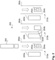
- Fig. 2 schematically illustrates a cryogenic fuel station 200 according to another preferred embodiment of the invention.
- the fuel station 200 is shown in a top view. Only some parts of the fuel station 200 are shown for explanation.
- the fuel station 200 comprises, by means of example, three fuel dispensing systems 210a, 210b, 210c with corresponding vehicle lanes 264a, 264b, 264c, indicated with arrows and markings on the ground, for example.
- Each of the fuel dispensing systems 210a, 210b, 210c comprises a respective a fuel dispensing apparatus 220a, 220b, 220c.
- Each of the fuel dispensing systems 210a, 210b, 210c can be supplied with fuel via a respective fuel supply system from a reservoir (not shown here). A common reservoir for all fuel dispensing systems can be used. Also, each of the fuel dispensing systems 210a, 210b, 210c can comprise a respective cooling system (not shown here). Further, each of the fuel dispensing systems 210a, 210b, 210c comprises a presence sensor 252a, 252b, 252c in order to detect presence of a fuel receiver, e.g., truck 260 shown here.
- a fuel receiver e.g., truck 260 shown here.
- a pre-defined area 254a, 254b, 254c can be defined, each being a part of the respective vehicle lane 264a, 264b, 264c next to the respective fuel dispensing apparatus 220a, 220b, 220c.
- Each of the fuel dispensing systems 210a, 210b, 210c can be of the same type and/or operate in the same way as the fuel dispensing system 110 shown in Fig. 1 and described above.
- different presence sensors are shown in Fig. 2 .
- Presence sensor 252a is an inductive sensor (like for Fig. 1 )
- presence sensor 252b is a video camera
- presence sensor 252c is a mechanical sensor.
- Each of the presence sensors allows detecting presence of a fuel receiver like the vehicle or truck 260 being present in the respective defined area 254a, 254b, 254c
- Fig. 3 illustrates a method according to a preferred embodiment of the invention in a flow diagram. This method can be carried out with the fuel dispensing system 110 of Fig. 1 or with each of the fuel dispensing systems 210a, 210b, 210c of Fig. 2 , for example.
- step 300 sensor information from the presence sensor are received.
- step 302 based on the sensor information, presence of a fuel receiver is detected, if any fuel receiver can be detected. For example, a fuel receiver is detected to be present if a fuel receiver is present within a pre-defined area with respect to the fuel dispensing system, e.g., the vehicle lanes or parts thereof shown in Fig. 2 , and/or for at least a pre-defined time period, e.g., 10 seconds.
- step 304 the cooling system is caused cool down the at least part of the fuel supply system and/or at least part of the fuel dispensing apparatus dispensing fuel apparatus. It is noted that in this way the equipment can be cooled down prior to the actual start of the fuel dispensing. After the fuel receiver or vehicle has stopped, the user can make a payment, connect the fuel dispensing apparatus of the vehicle and then push a button to start the fuel dispensing. Thus, in step 306, the fuel dispensing apparatus is caused to start dispensing the fuel to said fuel receiver upon receiving a user input.
- the cooling system is caused to stop cooling down the at least part of the fuel supply system and/or at least part of the fuel dispensing apparatus dispensing fuel apparatus. This is the case, if the fuel receiver is not present within said pre-defined area and/or for at least a further pre-defined time period, after cooling down had been started. For example, after a vehicle has been fuelled and left the fuel station and if for a certain time no further vehicle arrives in the same vehicle line, the cooling down will be stopped for energy savings.
Landscapes
- Engineering & Computer Science (AREA)
- Mechanical Engineering (AREA)
- General Engineering & Computer Science (AREA)
- Filling Or Discharging Of Gas Storage Vessels (AREA)
- Loading And Unloading Of Fuel Tanks Or Ships (AREA)
Priority Applications (2)
| Application Number | Priority Date | Filing Date | Title |
|---|---|---|---|
| EP23315280.0A EP4491935A1 (fr) | 2023-07-12 | 2023-07-12 | Procédé de fonctionnement d'un système de distribution de carburant et système de distribution de carburant |
| PCT/EP2024/025206 WO2025011779A1 (fr) | 2023-07-12 | 2024-07-09 | Procédé de fonctionnement d'un système de distribution de carburant et système de distribution de carburant |
Applications Claiming Priority (1)
| Application Number | Priority Date | Filing Date | Title |
|---|---|---|---|
| EP23315280.0A EP4491935A1 (fr) | 2023-07-12 | 2023-07-12 | Procédé de fonctionnement d'un système de distribution de carburant et système de distribution de carburant |
Publications (1)
| Publication Number | Publication Date |
|---|---|
| EP4491935A1 true EP4491935A1 (fr) | 2025-01-15 |
Family
ID=87567341
Family Applications (1)
| Application Number | Title | Priority Date | Filing Date |
|---|---|---|---|
| EP23315280.0A Withdrawn EP4491935A1 (fr) | 2023-07-12 | 2023-07-12 | Procédé de fonctionnement d'un système de distribution de carburant et système de distribution de carburant |
Country Status (2)
| Country | Link |
|---|---|
| EP (1) | EP4491935A1 (fr) |
| WO (1) | WO2025011779A1 (fr) |
Citations (4)
| Publication number | Priority date | Publication date | Assignee | Title |
|---|---|---|---|---|
| US20120125482A1 (en) * | 2009-07-30 | 2012-05-24 | Toyota Jidosha Kabushiki Kaisha | Gas filling system |
| JP2017187057A (ja) * | 2016-04-01 | 2017-10-12 | 株式会社タツノ | ガス充填装置 |
| CN114466989A (zh) * | 2019-10-07 | 2022-05-10 | 宝马股份公司 | 用于给机动车加燃料的方法、机动车、加燃料站和计算机可读存储介质 |
| EP4119493A1 (fr) * | 2021-07-15 | 2023-01-18 | me energy GmbH | Colonne de charge avec réservoir de carburant et dispositif de ventilation |
Family Cites Families (1)
| Publication number | Priority date | Publication date | Assignee | Title |
|---|---|---|---|---|
| CN109964074B (zh) * | 2016-12-06 | 2021-10-26 | 乔治洛德方法研究和开发液化空气有限公司 | 氢气加注系统 |
-
2023
- 2023-07-12 EP EP23315280.0A patent/EP4491935A1/fr not_active Withdrawn
-
2024
- 2024-07-09 WO PCT/EP2024/025206 patent/WO2025011779A1/fr not_active Ceased
Patent Citations (4)
| Publication number | Priority date | Publication date | Assignee | Title |
|---|---|---|---|---|
| US20120125482A1 (en) * | 2009-07-30 | 2012-05-24 | Toyota Jidosha Kabushiki Kaisha | Gas filling system |
| JP2017187057A (ja) * | 2016-04-01 | 2017-10-12 | 株式会社タツノ | ガス充填装置 |
| CN114466989A (zh) * | 2019-10-07 | 2022-05-10 | 宝马股份公司 | 用于给机动车加燃料的方法、机动车、加燃料站和计算机可读存储介质 |
| EP4119493A1 (fr) * | 2021-07-15 | 2023-01-18 | me energy GmbH | Colonne de charge avec réservoir de carburant et dispositif de ventilation |
Also Published As
| Publication number | Publication date |
|---|---|
| WO2025011779A1 (fr) | 2025-01-16 |
Similar Documents
| Publication | Publication Date | Title |
|---|---|---|
| US11041734B2 (en) | Systems and methods for optimizing a travel route of a hybrid-electric vehicle inside an emissions-free zone | |
| CN104778788A (zh) | 汽车自动加油并付费系统 | |
| US11040596B2 (en) | Vehicle control device and delivery system | |
| US9169115B2 (en) | Method and device for reducing the likelihood of theft at a gas station or a charging station for motor vehicles | |
| EP3679291B1 (fr) | Système de ravitaillement en hydrogène et procédé de ravitaillement en hydrogène | |
| CN105894669A (zh) | 无人驾驶车辆自动加油的方法、装置及系统 | |
| RU2010147872A (ru) | Способ контроля маршрута доставки топлива | |
| US10138112B2 (en) | Smart fuel dispenser for efficient fuel delivery | |
| CN105243870A (zh) | 提供车位信息的方法、装置和系统 | |
| CN106297023A (zh) | 加油机的加油方法、车辆的加油方法和加油系统 | |
| WO2022176108A1 (fr) | Dispositif de présentation d'informations, dispositif de commande de véhicule, terminal de présentation d'informations, système de présentation d'informations et procédé de présentation d'informations | |
| CN111806368B (zh) | 车载显示屏控制方法、计算机可读存储介质和电子设备 | |
| WO2025011779A1 (fr) | Procédé de fonctionnement d'un système de distribution de carburant et système de distribution de carburant | |
| CN113532469A (zh) | 导航方法、装置、电子设备及存储介质 | |
| US20210279664A1 (en) | Control apparatus, vehicle, non-transitory computer readable medium, and control method | |
| US12312233B2 (en) | Intelligent liquid level display for auxiliary tanks | |
| CN111260352B (zh) | 利用传感器的加油机识别系统及控制该系统的方法 | |
| KR20120006069U (ko) | 휴대용전자장치을 이용한 주유셋팅 시스템 | |
| JP2018100926A (ja) | エネルギー補給支援装置、エネルギー補給支援システム及びプログラム | |
| CN112309048A (zh) | 基于etc的加油站收费方法及加油站收费设备 | |
| CN101722905B (zh) | 车辆用数据通信系统、车载终端装置以及中心 | |
| WO2018004425A1 (fr) | Procédé et système de détermination de l'activité d'au moins un véhicule dans un groupe de véhicules | |
| JP4787116B2 (ja) | 燃料供給システム | |
| KR102455571B1 (ko) | 스마트 주유결제 시스템 및 방법 | |
| KR20150080395A (ko) | 스마트폰 결제기와 nfc태그를 이용한 유가 보조금 제어기, 유가 보조금 제어 시스템 및 화물복지 신용카드 결제 및 승인 방법 |
Legal Events
| Date | Code | Title | Description |
|---|---|---|---|
| PUAI | Public reference made under article 153(3) epc to a published international application that has entered the european phase |
Free format text: ORIGINAL CODE: 0009012 |
|
| STAA | Information on the status of an ep patent application or granted ep patent |
Free format text: STATUS: THE APPLICATION HAS BEEN PUBLISHED |
|
| AK | Designated contracting states |
Kind code of ref document: A1 Designated state(s): AL AT BE BG CH CY CZ DE DK EE ES FI FR GB GR HR HU IE IS IT LI LT LU LV MC ME MK MT NL NO PL PT RO RS SE SI SK SM TR |
|
| STAA | Information on the status of an ep patent application or granted ep patent |
Free format text: STATUS: THE APPLICATION IS DEEMED TO BE WITHDRAWN |
|
| 18D | Application deemed to be withdrawn |
Effective date: 20250716 |