EP4491945A1 - Dispositif de gazéification pour foyer à combustion de gazéification - Google Patents
Dispositif de gazéification pour foyer à combustion de gazéification Download PDFInfo
- Publication number
- EP4491945A1 EP4491945A1 EP24185016.3A EP24185016A EP4491945A1 EP 4491945 A1 EP4491945 A1 EP 4491945A1 EP 24185016 A EP24185016 A EP 24185016A EP 4491945 A1 EP4491945 A1 EP 4491945A1
- Authority
- EP
- European Patent Office
- Prior art keywords
- gasification
- liquid
- chamber
- liquid level
- gasification chamber
- Prior art date
- Legal status (The legal status is an assumption and is not a legal conclusion. Google has not performed a legal analysis and makes no representation as to the accuracy of the status listed.)
- Granted
Links
Images

Classifications
-
- F—MECHANICAL ENGINEERING; LIGHTING; HEATING; WEAPONS; BLASTING
- F23—COMBUSTION APPARATUS; COMBUSTION PROCESSES
- F23D—BURNERS
- F23D5/00—Burners in which liquid fuel evaporates in the combustion space, with or without chemical conversion of evaporated fuel
- F23D5/12—Details
- F23D5/123—Inserts promoting evaporation
-
- F—MECHANICAL ENGINEERING; LIGHTING; HEATING; WEAPONS; BLASTING
- F23—COMBUSTION APPARATUS; COMBUSTION PROCESSES
- F23K—FEEDING FUEL TO COMBUSTION APPARATUS
- F23K5/00—Feeding or distributing other fuel to combustion apparatus
- F23K5/02—Liquid fuel
- F23K5/14—Details thereof
- F23K5/22—Vaporising devices
-
- F—MECHANICAL ENGINEERING; LIGHTING; HEATING; WEAPONS; BLASTING
- F23—COMBUSTION APPARATUS; COMBUSTION PROCESSES
- F23D—BURNERS
- F23D11/00—Burners using a direct spraying action of liquid droplets or vaporised liquid into the combustion space
- F23D11/36—Details
- F23D11/44—Preheating devices; Vaporising devices
- F23D11/441—Vaporising devices incorporated with burners
- F23D11/448—Vaporising devices incorporated with burners heated by electrical means
-
- F—MECHANICAL ENGINEERING; LIGHTING; HEATING; WEAPONS; BLASTING
- F23—COMBUSTION APPARATUS; COMBUSTION PROCESSES
- F23D—BURNERS
- F23D5/00—Burners in which liquid fuel evaporates in the combustion space, with or without chemical conversion of evaporated fuel
- F23D5/12—Details
- F23D5/14—Maintaining predetermined amount of fuel in evaporator
-
- F—MECHANICAL ENGINEERING; LIGHTING; HEATING; WEAPONS; BLASTING
- F24—HEATING; RANGES; VENTILATING
- F24C—DOMESTIC STOVES OR RANGES ; DETAILS OF DOMESTIC STOVES OR RANGES, OF GENERAL APPLICATION
- F24C5/00—Stoves or ranges for liquid fuels
- F24C5/16—Arrangement or mounting of control or safety devices
-
- F—MECHANICAL ENGINEERING; LIGHTING; HEATING; WEAPONS; BLASTING
- F23—COMBUSTION APPARATUS; COMBUSTION PROCESSES
- F23K—FEEDING FUEL TO COMBUSTION APPARATUS
- F23K2300/00—Pretreatment and supply of liquid fuel
- F23K2300/20—Supply line arrangements
- F23K2300/205—Vaporising
Definitions
- the present invention relates to the field of gasification devices, and relates in particular to a gasification device for a gasification combustion fireplace.
- An alcohol fireplace is a real-fire fireplace that uses environmentally friendly renewable energy bioethanol as fuel and brings people warm enjoyment. Moreover, it is simple to install and flexible in design, and is thus favored by more and more users. In particular, an alcohol fireplace that burns alcohol fuel after gasification has a more complete and uniform fuel combustion, and a stable and safe flame.
- devices for gasifying alcohol fuel currently on the market are generally composed of an electric heating device and a gasification chamber.
- the electric heating device directly heats a housing of the gasification chamber, and the inner wall of the housing has a simple shape only for accommodating liquid fuel, as in "FIREPLACE FOR GASIFYING AND BURNING LIQUID FUEL" mentioned in Patent Application No. CN201110219779.2 .
- the heating area of the housing of the gasification chamber for liquid fuel is not sufficiently large, and the heating is non-uniform, so that the gasification process of alcohol fuel in the gasification chamber is non-uniform, and the alcohol fuel is easily locally overheated to cause explosive boiling.
- gasification chambers currently on the market are integrated with burners, or are arranged very close to the burners and fixedly connected to the burners by using metal channels, so that the heat generated by the flames on the burners is easily returned to the gasification chambers, which affects the gasification rate of the gasification chambers.
- the liquid alcohol fuel in the gasification chambers may even be explosively boiled, and the liquid alcohol fuel in the gasification chambers is directly sprayed into the combustion chambers, so that the flames are suddenly increased in size and burn violently, resulting in a safety hazard.
- the problem to be solved by the present invention is to provide a gasification device for a gasification combustion fireplace, so as to overcome the defects of instability and easy explosive boiling in the alcohol gasification process of the existing alcohol fuel gasification combustion fireplace.
- the present invention provides a gasification device for a gasification combustion fireplace, comprising a gasification chamber, a gasification chamber lid, electric heating elements, a base, and a controller, wherein the gasification chamber has a gasification chamber inner cavity, and the base is provided below the gasification chamber; several electric heating elements are provided, and are completely enclosed between a lower surface of the gasification chamber and the base, and the electric heating elements are electrically connected to the controller; a gasification chamber liquid inlet port is provided below the gasification chamber; several cooling fins are further provided in the gasification chamber inner cavity, and the cooling fins are connected to a lower surface of the gasification chamber inner cavity and are arranged close to the heating elements; channels for liquid circulation are provided between a plurality of fins and between the fins and an inner wall of the gasification chamber; and the gasification chamber lid is provided above the gasification chamber and seals the gasification chamber inner cavity so that the gasification chamber inner cavity becomes a closed space, and several gas outlet ports are provided on the gasification chamber
- the gasification device further comprises a liquid level control chamber, a liquid level detecting device is provided in the liquid level control chamber, and the liquid level detecting device is electrically connected to the controller; and the liquid level detecting device is provided with a safety liquid level detecting probe, a low liquid level detecting probe, a middle liquid level detecting probe, and a high liquid level detecting probe in sequence from bottom to top, the safety liquid level detecting probe is higher than the lowest point of a lower surface of the gasification chamber inner cavity, the low liquid level detecting probe is higher than the electric heating elements, and the high liquid level detecting probe is lower than upper surfaces of the cooling fins.
- the liquid level control chamber is provided with a liquid level control chamber liquid outlet port communicating with the gasification chamber liquid inlet port through a gasification chamber liquid inlet pipe;
- the gasification chamber liquid inlet pipe is arranged to not be higher than the liquid level control chamber liquid outlet port and/or the gasification chamber liquid inlet port;
- the liquid level control chamber is further provided with a liquid level control chamber liquid supply port, and the liquid level control chamber liquid supply port is connected to a liquid supply pipe; and an inner diameter of the gasification chamber liquid inlet pipe is larger than an inner diameter of the liquid supply pipe.
- the liquid level control chamber is provided with an overflow port, and the overflow port is higher than the high liquid level detecting probe.
- the gasification device further comprises an overflow liquid storage chamber; the overflow liquid storage chamber is provided with an overflow pipe communicating with the overflow port; and the overflow liquid storage chamber is provided at a height lower than that of the overflow port.
- the overflow liquid storage chamber is provided with a liquid level alarm device therein, and the liquid level alarm device is electrically connected to the controller;
- the overflow liquid storage chamber is provided with a vent.
- the gasification device further comprises a liquid return pump
- the liquid level control chamber is provided with a liquid level control chamber liquid return port
- the liquid return pump is connected to the liquid level control chamber liquid return port through a liquid return pump liquid inlet pipe
- an outlet of the liquid return pump is connected to a fuel storage device of a product through a liquid return pump liquid outlet pipe.
- the gasification chamber is made of aluminum or copper material having high thermal conductivity; and a sealing gasket is provided between the gasification chamber and the gasification chamber lid.
- the gasification device for a gasification combustion fireplace provided by the present invention, by adding the cooling fins to the gasification chamber inner cavity, the gasification process of the liquid fuel is heated more uniformly, which effectively solves the problems in the prior art that the liquid fuel in the gasification chamber is heated and gasified non-uniformly and the explosive boiling phenomenon easily occurs, so that the liquid fuel can be stably supplied to the burner for combustion, and the flame stability is greatly improved.
- the problems of instability and easy explosive boiling in the alcohol gasification process of the existing alcohol fuel gasification combustion fireplace are overcome.
- the present invention provides a gasification device for a gasification combustion fireplace.
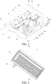
- the gasification device includes a gasification chamber 1, a gasification chamber lid 2, electric heating elements 3, a base 4, a controller 5, a liquid level control chamber 6, a temperature detecting device 7, and a gas outlet pipe 8.
- a gasification chamber 1 has a container structure including an inner cavity 11 and made of a material having a high thermal conductivity such as aluminum or copper, and the base 4 is provided below the gasification chamber 1.
- the number of electric heating elements 3 is two, the two electric heating elements 3 are provided between a lower surface of the gasification chamber 1 and the base 4, and the lower surface of the gasification chamber 1 and the base 4 completely enclose the electric heating elements 3.
- the gasification chamber 1 is further provided with a gasification chamber liquid inlet port 12 communicating with a lower surface of the gasification chamber inner cavity 11.
- cooling fins 13 are further provided in the gasification chamber inner cavity 11, and the cooling fins 13 are connected to the lower surface of the gasification chamber inner cavity 11 and are arranged close to the heating elements 3.
- Channels 14 for liquid circulation are provided between a plurality of fins 13 and between the fins 13 and an inner wall of the gasification chamber inner cavity 11.
- the gasification chamber lid 2 is provided above the gasification chamber 1, a sealing gasket 22 is provided between the gasification chamber lid 2 and the gasification chamber 1, and the gasification chamber lid 2 and the sealing gasket 22 seal the gasification chamber inner cavity 11 so that the gasification chamber inner cavity becomes a closed space.
- the gasification chamber lid 2 is further provided with two gas outlet ports 21.
- the gas outlet ports 21 are connected to a gas outlet pipe 8, the other end of the gas outlet pipe 8 is connected to a burner of a product, and the gas outlet pipe 8 is made of a non-metal pipe having low thermal conductivity.
- the electric heating elements 3 are connected to the controller 5.
- the controller 5 can control the operation of the electric heating elements 3, and common heating rods may be adopted as the electric heating elements 3.
- the temperature detecting device 7 is provided inside the gasification chamber inner cavity 11 and mounted on the gasification chamber lid 2.
- the temperature detecting device 7 is connected to the controller 5, and a common temperature detecting probe may be adopted as the temperature detecting device 7.
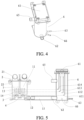
- the liquid level control chamber 6 is provided with a liquid level detecting device 61 connected to the controller 5.
- the liquid level detecting device 61 is provided with four liquid level detecting probes, i.e., a safety liquid level detecting probe 611, a low liquid level detecting probe 612, a middle liquid level detecting probe 613, and a high liquid level detecting probe 614 in sequence from bottom to top.
- the safety liquid level detecting probe 611 is higher than the lowest point of the lower surface of the gasification chamber inner cavity 11, the low liquid level detecting probe 612 is higher than the electric heating elements 3, and the high liquid level detecting probe 614 is lower than upper surfaces of the cooling fins 13.
- the liquid level control chamber 6 is provided with a liquid level control chamber liquid outlet port 62.
- the liquid level control chamber liquid outlet port 62 and the gasification chamber liquid inlet port 12 are connected through a gasification chamber liquid inlet pipe 15.
- the gasification chamber liquid inlet pipe 15 is arranged so as not to be higher than the liquid level control chamber liquid outlet port 62 and/or the gasification chamber liquid inlet port 12, that is, the gasification chamber 1 and the liquid level control chamber 6 form a set of communicating vessels, and the liquid level of the gasification chamber inner cavity changes synchronously with the liquid level in the liquid level control chamber 6.
- the liquid level control chamber 6 is further provided with a liquid level control chamber liquid supply port 63.
- the liquid level control chamber liquid supply port 63 is connected to a liquid supply pipe 64 for supplying liquid fuel to the gasification device of the present embodiment, and the inner diameter of the gasification chamber liquid inlet pipe 15 is much larger than the inner diameter of the liquid supply pipe 64.
- the gasification device further comprises an overflow liquid storage chamber 9.
- An overflow pipe 91 is provided on the overflow liquid storage chamber 9, an overflow port 65 is provided on the liquid level control chamber 6, the overflow liquid storage chamber 9 is connected to the overflow port 65 through the overflow pipe 91, and the overflow liquid storage chamber 9 is provided below the overflow port 65.
- a liquid level alarm device 92 is provided below a side surface of the overflow liquid storage chamber 9, and the liquid level alarm device 92 is connected to the controller 5.
- the liquid level alarm device 92 is known in the art, and will not be described again.
- a vent 93 is further provided at the top of the overflow liquid storage chamber 9.
- the gasification device further includes a liquid return pump 10.
- the liquid level control chamber 6 is provided with a liquid level control chamber liquid return port 66, the liquid return pump 10 is connected to the liquid level control chamber liquid return port 66 through a liquid return pump liquid inlet pipe 101, and an outlet of the liquid return pump 10 is connected to a fuel storage device of the product through a liquid return pump liquid outlet pipe 102.
- the operating principle of this embodiment is as follows: In operation, the liquid level control chamber 6 is supplied with liquid at a constant average rate through the liquid supply pipe 64, and when the liquid level in the liquid level control chamber 6 is above a safety level, the controller 5 controls the electric heating elements 3 to start heating. Since the gasification chamber inner cavity 11 communicates with the liquid level control chamber 6, and the inner diameter of the gasification chamber liquid inlet pipe 15 is much larger than the inner diameter of the liquid supply pipe 64, the liquid level in the gasification chamber inner cavity 11 is always the same as the liquid level in the liquid level control chamber 6. The liquid fuel in the gasification chamber inner cavity 11 is gasified under the heating action of the electric heating elements 3.
- the controller 5 adjusts the heating power of the electric heating elements 3 in real time according to the change of the liquid level detected by the liquid level detecting device 61, so that the liquid level in the liquid level control chamber 6 is always between the high liquid level detecting probe 614 and the low liquid level detecting probe 612. Since the gasification chamber 1 in this embodiment is made of material having high thermal conductivity such as aluminum or copper, and the cooling fins 13 are provided in the gasification chamber inner cavity 11, the liquid fuel in the gasification chamber inner cavity 11 is heated more uniformly, and the gasification process is more stable and controllable.
- the average rate at which the liquid is supplied through the liquid supply pipe 64 is constant, so the average rate at which the gaseous fuel is supplied to the outside through the gas outlet pipe 8 is also constant, making the flame combustion more stable.
- the liquid fuel remaining in the liquid level control chamber 6 and the gasification chamber 1 can be pumped back to a fuel storage container by the liquid return pump 10, so that the liquid fuel is prevented from being stored in the gasification chamber 1 and the liquid level control chamber 6 for a long time when the product is not in operation.
- the overflown liquid fuel can flow to the overflow liquid storage chamber 9 through the overflow pipe 91 for storage, and the liquid level alarm device 92 can timely feedback a signal to the controller 5 to provide an alarm and stop the liquid supply of the liquid supply pipe 64 and the heating operation of the electric heating elements 3.
- the liquid return pump 10 executes an end program.
- the pressure in the overflow liquid storage chamber 9 is balanced with the outside, so that the pressure does not increase due to the continuous inflow of the liquid fuel. Since the overflow port 65 communicates with the overflow liquid storage chamber 9, the overflow port 65 may serve as a breathing port of the liquid level control chamber 6. Therefore, the pressure in the liquid level control chamber 6 does not increase due to continuous inflow of the liquid, thereby ensuring smooth operation of the entire device.
- the gasification device for a gasification combustion fireplace provided in this embodiment, by adding the cooling fins to the gasification chamber inner cavity, the gasification process of the liquid fuel is heated more uniformly, effectively solving the problems in the prior art that the liquid fuel in the gasification chamber is heated and gasified non-uniformly and the explosive boiling phenomenon easily occurs, so that the liquid fuel can be stably supplied to the burner for combustion, and the flame stability is greatly improved.
- the problems of instability and easy explosive boiling in the alcohol gasification process of the existing alcohol fuel gasification combustion fireplace are overcome.
Landscapes
- Engineering & Computer Science (AREA)
- Chemical & Material Sciences (AREA)
- Combustion & Propulsion (AREA)
- Mechanical Engineering (AREA)
- General Engineering & Computer Science (AREA)
- Spray-Type Burners (AREA)
Applications Claiming Priority (1)
| Application Number | Priority Date | Filing Date | Title |
|---|---|---|---|
| CN202321763972.7U CN220338563U (zh) | 2023-07-06 | 2023-07-06 | 一种用于气化燃烧壁炉的气化装置 |
Publications (3)
| Publication Number | Publication Date |
|---|---|
| EP4491945A1 true EP4491945A1 (fr) | 2025-01-15 |
| EP4491945B1 EP4491945B1 (fr) | 2025-12-24 |
| EP4491945C0 EP4491945C0 (fr) | 2025-12-24 |
Family
ID=89444104
Family Applications (1)
| Application Number | Title | Priority Date | Filing Date |
|---|---|---|---|
| EP24185016.3A Active EP4491945B1 (fr) | 2023-07-06 | 2024-06-27 | Dispositif de gazéification pour foyer à combustion de gazéification |
Country Status (5)
| Country | Link |
|---|---|
| US (1) | US20250012441A1 (fr) |
| EP (1) | EP4491945B1 (fr) |
| CN (1) | CN220338563U (fr) |
| ES (1) | ES3059253T3 (fr) |
| PL (1) | PL4491945T3 (fr) |
Families Citing this family (1)
| Publication number | Priority date | Publication date | Assignee | Title |
|---|---|---|---|---|
| CN118757808A (zh) * | 2024-07-05 | 2024-10-11 | 宁波丽辰电器有限公司 | 一种壁炉熄火方法及壁炉 |
Citations (4)
| Publication number | Priority date | Publication date | Assignee | Title |
|---|---|---|---|---|
| GB858875A (en) * | 1958-08-28 | 1961-01-18 | Frank Wykes | Improvements in and connected with liquid fuel burners |
| CN102330975A (zh) * | 2011-07-29 | 2012-01-25 | 宁波丽辰电器有限公司 | 一种液体燃料的气化燃烧装置 |
| US20140158111A1 (en) * | 2011-07-29 | 2014-06-12 | Ningbo Richen Electrical Appliance Co., Ltd | Fireplace of Combusting Gasified Liquid Fuel |
| CN108087921A (zh) * | 2018-01-23 | 2018-05-29 | 广东吉宝电器科技有限公司 | 一种液体燃料炉具的燃料气化装置 |
-
2023
- 2023-07-06 CN CN202321763972.7U patent/CN220338563U/zh active Active
-
2024
- 2024-06-27 PL PL24185016.3T patent/PL4491945T3/pl unknown
- 2024-06-27 EP EP24185016.3A patent/EP4491945B1/fr active Active
- 2024-06-27 ES ES24185016T patent/ES3059253T3/es active Active
- 2024-07-03 US US18/763,133 patent/US20250012441A1/en active Pending
Patent Citations (4)
| Publication number | Priority date | Publication date | Assignee | Title |
|---|---|---|---|---|
| GB858875A (en) * | 1958-08-28 | 1961-01-18 | Frank Wykes | Improvements in and connected with liquid fuel burners |
| CN102330975A (zh) * | 2011-07-29 | 2012-01-25 | 宁波丽辰电器有限公司 | 一种液体燃料的气化燃烧装置 |
| US20140158111A1 (en) * | 2011-07-29 | 2014-06-12 | Ningbo Richen Electrical Appliance Co., Ltd | Fireplace of Combusting Gasified Liquid Fuel |
| CN108087921A (zh) * | 2018-01-23 | 2018-05-29 | 广东吉宝电器科技有限公司 | 一种液体燃料炉具的燃料气化装置 |
Also Published As
| Publication number | Publication date |
|---|---|
| ES3059253T3 (en) | 2026-03-19 |
| PL4491945T3 (pl) | 2026-03-16 |
| EP4491945B1 (fr) | 2025-12-24 |
| US20250012441A1 (en) | 2025-01-09 |
| EP4491945C0 (fr) | 2025-12-24 |
| CN220338563U (zh) | 2024-01-12 |
Similar Documents
| Publication | Publication Date | Title |
|---|---|---|
| JP3637065B2 (ja) | 毛管供給ボイラ | |
| EP4491945B1 (fr) | Dispositif de gazéification pour foyer à combustion de gazéification | |
| JP2012042068A (ja) | 水素調理装置 | |
| CN106969353A (zh) | 一种燃烧装置 | |
| CN211976941U (zh) | 一种室内使用的新型取暖壁炉 | |
| US5724887A (en) | Frying device | |
| CN205655357U (zh) | 一种利用余热产生蒸汽的炉灶 | |
| KR100502575B1 (ko) | 열교환식 보일러 | |
| CN210921481U (zh) | 一种新能源燃烧系统 | |
| CN210951406U (zh) | 旋喷式常压气化炉头 | |
| CN215570740U (zh) | 一种蒸汽节能灶 | |
| CN211345415U (zh) | 一种多功能汽化炉 | |
| CN204105691U (zh) | 燃气不粘底汤粥炉 | |
| CN219306485U (zh) | 一种防溢水的电蒸箱 | |
| CN216307764U (zh) | 一种电气自动化燃气锅炉 | |
| CN223860683U (zh) | 烹饪设备 | |
| CN219913150U (zh) | 燃气灶 | |
| CN219656132U (zh) | 燃气灶 | |
| CN222604055U (zh) | 一种易于添加酒精的火炉桌 | |
| CN218721479U (zh) | 一种外环火盖 | |
| CN111174190A (zh) | 水电阻工业锅炉 | |
| KR200348367Y1 (ko) | 브라운가스 발열장치를 이용한 관류형 증기보일러 | |
| CN219500856U (zh) | 一种烹饪器具 | |
| CN217816681U (zh) | 一种咖啡机火电一体蒸汽热水锅炉 | |
| CN217082630U (zh) | 一种燃气灶 |
Legal Events
| Date | Code | Title | Description |
|---|---|---|---|
| PUAI | Public reference made under article 153(3) epc to a published international application that has entered the european phase |
Free format text: ORIGINAL CODE: 0009012 |
|
| STAA | Information on the status of an ep patent application or granted ep patent |
Free format text: STATUS: THE APPLICATION HAS BEEN PUBLISHED |
|
| AK | Designated contracting states |
Kind code of ref document: A1 Designated state(s): AL AT BE BG CH CY CZ DE DK EE ES FI FR GB GR HR HU IE IS IT LI LT LU LV MC ME MK MT NL NO PL PT RO RS SE SI SK SM TR |
|
| STAA | Information on the status of an ep patent application or granted ep patent |
Free format text: STATUS: REQUEST FOR EXAMINATION WAS MADE |
|
| 17P | Request for examination filed |
Effective date: 20250523 |
|
| GRAP | Despatch of communication of intention to grant a patent |
Free format text: ORIGINAL CODE: EPIDOSNIGR1 |
|
| STAA | Information on the status of an ep patent application or granted ep patent |
Free format text: STATUS: GRANT OF PATENT IS INTENDED |
|
| INTG | Intention to grant announced |
Effective date: 20250721 |
|
| RIC1 | Information provided on ipc code assigned before grant |
Ipc: F23D 5/12 20060101AFI20250711BHEP Ipc: F23D 5/14 20060101ALI20250711BHEP Ipc: F23D 11/44 20060101ALI20250711BHEP |
|
| GRAS | Grant fee paid |
Free format text: ORIGINAL CODE: EPIDOSNIGR3 |
|
| GRAA | (expected) grant |
Free format text: ORIGINAL CODE: 0009210 |
|
| STAA | Information on the status of an ep patent application or granted ep patent |
Free format text: STATUS: THE PATENT HAS BEEN GRANTED |
|
| AK | Designated contracting states |
Kind code of ref document: B1 Designated state(s): AL AT BE BG CH CY CZ DE DK EE ES FI FR GB GR HR HU IE IS IT LI LT LU LV MC ME MK MT NL NO PL PT RO RS SE SI SK SM TR |
|
| REG | Reference to a national code |
Ref country code: CH Ref legal event code: F10 Free format text: ST27 STATUS EVENT CODE: U-0-0-F10-F00 (AS PROVIDED BY THE NATIONAL OFFICE) Effective date: 20251224 Ref country code: GB Ref legal event code: FG4D |
|
| REG | Reference to a national code |
Ref country code: DE Ref legal event code: R096 Ref document number: 602024001815 Country of ref document: DE |
|
| U01 | Request for unitary effect filed |
Effective date: 20260105 |
|
| U07 | Unitary effect registered |
Designated state(s): AT BE BG DE DK EE FI FR IT LT LU LV MT NL PT RO SE SI Effective date: 20260113 |
|
| REG | Reference to a national code |
Ref country code: ES Ref legal event code: FG2A Ref document number: 3059253 Country of ref document: ES Kind code of ref document: T3 Effective date: 20260319 |