EP4491947A2 - Agencement de séparateur à cyclone - Google Patents
Agencement de séparateur à cyclone Download PDFInfo
- Publication number
- EP4491947A2 EP4491947A2 EP24216131.3A EP24216131A EP4491947A2 EP 4491947 A2 EP4491947 A2 EP 4491947A2 EP 24216131 A EP24216131 A EP 24216131A EP 4491947 A2 EP4491947 A2 EP 4491947A2
- Authority
- EP
- European Patent Office
- Prior art keywords
- arrangement
- preceding apparatus
- crossover duct
- outlet
- flow channel
- Prior art date
- Legal status (The legal status is an assumption and is not a legal conclusion. Google has not performed a legal analysis and makes no representation as to the accuracy of the status listed.)
- Pending
Links
Images


Classifications
-
- F—MECHANICAL ENGINEERING; LIGHTING; HEATING; WEAPONS; BLASTING
- F23—COMBUSTION APPARATUS; COMBUSTION PROCESSES
- F23J—REMOVAL OR TREATMENT OF COMBUSTION PRODUCTS OR COMBUSTION RESIDUES; FLUES
- F23J15/00—Arrangements of devices for treating smoke or fumes
- F23J15/02—Arrangements of devices for treating smoke or fumes of purifiers, e.g. for removing noxious material
- F23J15/022—Arrangements of devices for treating smoke or fumes of purifiers, e.g. for removing noxious material for removing solid particulate material from the gasflow
- F23J15/027—Arrangements of devices for treating smoke or fumes of purifiers, e.g. for removing noxious material for removing solid particulate material from the gasflow using cyclone separators
-
- B—PERFORMING OPERATIONS; TRANSPORTING
- B01—PHYSICAL OR CHEMICAL PROCESSES OR APPARATUS IN GENERAL
- B01J—CHEMICAL OR PHYSICAL PROCESSES, e.g. CATALYSIS OR COLLOID CHEMISTRY; THEIR RELEVANT APPARATUS
- B01J8/00—Chemical or physical processes in general, conducted in the presence of fluids and solid particles; Apparatus for such processes
- B01J8/005—Separating solid material from the gas/liquid stream
- B01J8/0055—Separating solid material from the gas/liquid stream using cyclones
-
- B—PERFORMING OPERATIONS; TRANSPORTING
- B04—CENTRIFUGAL APPARATUS OR MACHINES FOR CARRYING-OUT PHYSICAL OR CHEMICAL PROCESSES
- B04C—APPARATUS USING FREE VORTEX FLOW, e.g. CYCLONES
- B04C5/00—Apparatus in which the axial direction of the vortex is reversed
- B04C5/02—Construction of inlets by which the vortex flow is generated, e.g. tangential admission, the fluid flow being forced to follow a downward path by spirally wound bulkheads, or with slightly downwardly-directed tangential admission
- B04C5/04—Tangential inlets
-
- B—PERFORMING OPERATIONS; TRANSPORTING
- B04—CENTRIFUGAL APPARATUS OR MACHINES FOR CARRYING-OUT PHYSICAL OR CHEMICAL PROCESSES
- B04C—APPARATUS USING FREE VORTEX FLOW, e.g. CYCLONES
- B04C5/00—Apparatus in which the axial direction of the vortex is reversed
- B04C5/08—Vortex chamber constructions
- B04C5/081—Shapes or dimensions
-
- B—PERFORMING OPERATIONS; TRANSPORTING
- B04—CENTRIFUGAL APPARATUS OR MACHINES FOR CARRYING-OUT PHYSICAL OR CHEMICAL PROCESSES
- B04C—APPARATUS USING FREE VORTEX FLOW, e.g. CYCLONES
- B04C9/00—Combinations with other devices, e.g. fans, expansion chambers, diffusors, water locks
Definitions
- the invention relates to a cyclone separator arrangement, comprising a preceding apparatus having an outlet and a cyclone separator having an inlet.
- Cyclone separators are widely used for separating or removing particles from gas flow generated e.g. in a reactor, a furnace, an oven, or a venturi. However, there is still a need for improve the efficiency of the cyclone separators.
- a cyclone separator arrangement comprising
- the horizontal cross-section of the preceding apparatus has a round shape
- the crossover duct is arranged to the round preceding apparatus so that a distal wall of the crossover duct is tangentially directed in respect of the preceding apparatus.
- the horizontal cross-section of the preceding apparatus has a round shape
- the distal wall has an offset in respect of the preceding apparatus, the offset being no more than 0.1 x D from a tangential plane of the preceding apparatus.
- the cross-sectional shape of the preceding apparatus is polygon, e.g. rectangle or square, and that the crossover duct is arranged at a vertical edge of the preceding apparatus so that a distal wall of the crossover duct is attached to said vertical edge.
- the cross-sectional shape of the preceding apparatus is polygon, e.g. rectangle or square, and a distal wall of the crossover duct has an offset in respect of a vertical edge of the preceding apparatus, the offset being no more than 0.1 x D from said vertical edge.
- the cross-sectional shape of the preceding apparatus is polygon, e.g. rectangle or square, and the distal wall of the crossover duct is perpendicular to an outlet wall of the preceding apparatus that comprises the outlet.
- a relation of the height H of the cross-over duct to the width d thereof is H/d ⁇ 3.75 at the outlet.
- the cross-sectional area of the crossover duct decreases towards the inlet.
- the width of the crossover duct is decreasing towards the inlet.
- the width of the crossover duct is decreasing towards the inlet so that a proximal wall of the crossover duct is arranged at a first angle ⁇ in relation to a distal wall thereof, wherein the first angle ⁇ ⁇ 40°.
- a bump is arranged in the flow channel for limiting the cross-sectional area of the flow channel.
- the height h of the bump in relation to width d of the flow channel is selected as: h/d ⁇ 0.3.
- the length l of the bump 11 in relation to height h thereof is selected as: l/h ⁇ 4.
- the preceding apparatus is a venturi apparatus having a round cross-section, the venturi apparatus comprising a feeding channel arrangement for feeding material in the venturi apparatus, wherein the feeding channel arrangement comprises one or more feeding channel(s) arranged, as seen from above, at a second angle ⁇ in relation to the direction of the distal wall of the crossover duct, wherein said second angle ⁇ is selected in range of 90° ⁇ 70°.
- the feeding channel arrangement of the venturi apparatus comprises one feeding channel only.
- the feeding channel arrangement comprises at least two feeding channels.
- the feeding channel arrangement is arranged on same side of a centre line of the venturi apparatus as the crossover duct.
- the feeding channel arrangement is arranged on opposite side of a centre line of the venturi apparatus as the crossover duct.
- the venturi apparatus has an expanded upper portion, and that the outlet is arranged to said expanded upper portion.
- Figure 1a is a schematic top view of a cyclone separator arrangement in partial cross-section
- Figure 1b is a schematic side view of the arrangement shown in Figure lain partial cross-section.
- the cyclone separator arrangement 100 comprises a preceding apparatus 1 having an outlet 2, a cyclone separator 3 having an inlet 4, and a crossover duct 5 connected to the outlet 2 and the inlet 4.
- the preceding apparatus 1 is a reactor, a furnace, an oven, or a venturi.
- the preceding apparatus 1 has a horizontal inner diameter D.
- the crossover duct 5 creates a flow channel 6 from the outlet 2 of the preceding apparatus 1 to the inlet 4 of the cyclone separator 3 and supplies gas flow comprising particles from the preceding apparatus 1 to the cyclone separator 3.
- the flow channel 6 is arranged asymmetrically in a horizontal cross-section of the preceding apparatus 1.
- the flow channel 6 has a cross-section having a height H and a width d at the outlet 2 of the preceding apparatus 1.
- the width d of the flow channel 6 relates to the inner diameter D of the preceding apparatus 1 such that 0.15 x D ⁇ d ⁇ 0.6 x D, preferably 0.175 x D ⁇ d ⁇ 0.6 x D, even more preferably 0.2 x D ⁇ d ⁇ 0.6 x D.
- the width d of the flow channel 6 is a dimension of the flow channel 6 in a horizontal plane crossing the centre of gravity CF of a flow-through area of the flow channel 6 at the outlet 2 of the preceding apparatus.
- the inner diameter D is a dimension of the preceding apparatus 1 in a horizontal plane crossing the centre of gravity CP of a flow-through area of the preceding apparatus 1 and being parallel to the width d of the flow channel 6.
- said horizontal plane is situated somewhere between upper and lower walls of cross over duct 5.
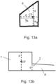
- Figures 13a and 13b are showing general principles for defining values of d and D.
- a relation of the height H of the cross-over duct 5 to the width d thereof is H/d ⁇ 3.75 at the outlet 2, such as 1 ⁇ H/d ⁇ 3.75.
- the flow channel 6 has a relatively narrow shape, guiding the particles away from the gas outlet of the cyclone apparatus.
- the flow channel 6 is not too narrow, thus allowing the particles at the outlet 2 of the preceding apparatus to be directed towards the duct wall.
- the horizontal cross-section of the preceding apparatus 1 has a round shape.
- the crossover duct 5 is arranged to the round preceding apparatus 1 so that a distal wall 7 of the crossover duct 5 is tangentially directed in respect of the preceding apparatus 1.
- Figure 2 is a schematic top view of another cyclone separator arrangement in partial cross-section.
- the distal wall 7 has an offset b in respect of the preceding apparatus 1.
- the offset b is no more than 0.1 x D from a tangential plane T of the preceding apparatus 1.
- Figure 3 is a schematic top view of a third cyclone separator arrangement in partial cross-section.
- the cross-sectional area of the crossover duct 5 decreases towards the inlet 4.
- the width d is decreasing towards the inlet 4.
- a proximal wall 10 of the crossover duct 5 is arranged at a first angle ⁇ in relation to a distal wall 7 thereof, wherein the first angle ⁇ ⁇ 40°. In another embodiment, the first angle ⁇ ⁇ 35°.
- Figure 4 is a schematic top view of a fourth cyclone separator arrangement in partial cross-section.
- the arrangement 100 comprises a bump 11 arranged in the flow channel 6.
- the bump 11 limits the cross-sectional area of the flow channel 6.
- the bump 11 is attached to the crossover duct 5 by e.g. welding.
- the bump 11 is an integral part of the crossover duct 5, i.e. shaped to the material of the crossover duct 5.
- the bump 11 is arranged to the proximal wall 10 of the crossover duct 5.
- relation of height h of the bump 11 to width d of the flow channel 6 is h/d ⁇ 0.3, preferably h/d ⁇ 0.25.
- relation of length l to height h of the bump 11 is l/h ⁇ 4, preferably l/h ⁇ 3.
- Figure 5a is a schematic top view of a fifth cyclone separator arrangement in partial cross-section
- Figure 5b is a schematic side view of the arrangement shown in Figure 5a in partial cross-section.
- the cross-sectional shape of the preceding apparatus 1 is polygon, such as rectangle.
- the cross-sectional shape of the preceding apparatus 1 is square.
- the crossover duct 5 is arranged at a vertical edge 8 of the preceding apparatus 1 so that a distal wall 7 of the crossover duct 5 is attached to said vertical edge 8.
- the distal wall 7 of the crossover duct 5 is perpendicular to an outlet wall 9 of the preceding apparatus that comprises the outlet 2.
- Figure 6 is a schematic top view of a sixth cyclone separator arrangement in partial cross-section.
- the distal wall 7 of the crossover duct 5 has an offset b in respect of a vertical edge 8 of the preceding apparatus 1.
- said offset b is not more than 0.1 x D from said vertical edge 8.
- Figure 7a is a schematic top view of a seventh cyclone separator arrangement in partial cross-section
- Figure 7b is a schematic side view of the arrangement shown in Figure 7a in partial cross-section.
- the preceding apparatus 1 is a venturi apparatus.
- the venturi apparatus 1 has a round cross-section, and it comprises a feeding channel arrangement 12 that is arranged for feeding material in the venturi apparatus. From a fluid dynamic perspective, the round cross-section of the venturi apparatus 1 may be preferable. However, in other embodiments, the cross-section of the venturi apparatus 1 may have another geometry, such as an oval or a polygon geometry.
- the venturi apparatus 1 has an expanded upper portion 14, and the outlet 2 is arranged to said expanded upper portion.
- the expanded upper portion 14 is arranged symmetrically in relation to the overall structure of the venture apparatus. Some embodiments having symmetrical upper portion are shown in Figures 7a - 8b .
- the feeding channel arrangement 12 of the venturi apparatus comprises one feeding channel 13 that is arranged, as seen from above, at a second angle ⁇ in relation to the direction of the distal wall 7 of the crossover duct 5.
- the second angle ⁇ is 90°.
- the second angle ⁇ is selected in range of 90° ⁇ 70°.
- the feeding channel arrangement 12 is arranged on opposite side of a centre line C of the venturi apparatus as the crossover duct 5.
- Figure 8a is a schematic top view of an eighth cyclone separator arrangement in partial cross-section
- Figure 8b is a schematic side view of the arrangement shown in Figure 8a in partial cross-section.
- the feeding channel arrangement 12 is arranged on same side of a centre line C of the venturi apparatus as the crossover duct 5. Also in this embodiment, the second angle ⁇ is selected in range of 90° ⁇ 70°.
- Figure 9a is a schematic top view of a ninth cyclone separator arrangement in partial cross-section
- Figure 9b is a schematic side view of the arrangement shown in Figure 9a in partial cross-section.
- the venturi apparatus 1 has an expanded upper portion 14 that is arranged asymmetrically in relation to the overall structure of the venture apparatus. Some embodiments having asymmetrical upper portion are shown in Figures 9a - 12 .
- the outlet 2 is arranged to said expanded upper portion.
- the feeding channel arrangement 12 is arranged on opposite side of a centre line C of the venturi apparatus as the crossover duct 5, as shown in Figures 9a, 9b .
- the feeding channel arrangement 12 is arranged on same side of a centre line C of the venturi apparatus as the crossover duct 5, as shown in Figures 10a, 10b .
- the centre line C is the centre line of the upper portion.
- Figure 11 is a schematic top view of an eleventh cyclone separator arrangement in partial cross-section
- Figure 12 is a schematic top view of a twelfth cyclone separator arrangement in partial cross-section.
- the feeding channel arrangement 12 comprises at least two feeding channels 13.
- the number of the feeding channels 13 may be even higher than three.
- the feeding channels 13 of the feeding channel arrangement 12 of the venturi apparatus are arranged in a second angle ⁇ in relation to the direction of the distal wall 7 of the crossover duct 5, the second angle ⁇ being selected in range of 90° ⁇ 70°.
- Figure 13a is showing principles for defining for defining values of d and H of a flow channel
- Figure 13b is showing principles for defining value D of a preceding apparatus.
- Said definition is based on the concept of the centre of gravity.
- a line intersecting said centre CF and parallel to the height of the preceding apparatus 1 is defined. This line represents the height H of the flow channel 6. Then, another line intersecting said centre CF but orthogonal to the height H of the preceding apparatus 1 is defined. This another line represents the width d of the flow channel 6.
Landscapes
- Physics & Mathematics (AREA)
- Fluid Mechanics (AREA)
- Geometry (AREA)
- Chemical & Material Sciences (AREA)
- Engineering & Computer Science (AREA)
- Organic Chemistry (AREA)
- Chemical Kinetics & Catalysis (AREA)
- Mechanical Engineering (AREA)
- General Engineering & Computer Science (AREA)
- Cyclones (AREA)
Priority Applications (1)
| Application Number | Priority Date | Filing Date | Title |
|---|---|---|---|
| EP24216131.3A EP4491947A3 (fr) | 2020-03-06 | 2020-03-06 | Agencement de séparateur à cyclone |
Applications Claiming Priority (3)
| Application Number | Priority Date | Filing Date | Title |
|---|---|---|---|
| EP24216131.3A EP4491947A3 (fr) | 2020-03-06 | 2020-03-06 | Agencement de séparateur à cyclone |
| PCT/FI2020/050145 WO2021176130A1 (fr) | 2020-03-06 | 2020-03-06 | Agencement de séparateur à cyclone |
| EP20922636.4A EP4114573B1 (fr) | 2020-03-06 | 2020-03-06 | Agencement de séparateur à cyclone |
Related Parent Applications (2)
| Application Number | Title | Priority Date | Filing Date |
|---|---|---|---|
| EP20922636.4A Division-Into EP4114573B1 (fr) | 2020-03-06 | 2020-03-06 | Agencement de séparateur à cyclone |
| EP20922636.4A Division EP4114573B1 (fr) | 2020-03-06 | 2020-03-06 | Agencement de séparateur à cyclone |
Publications (2)
| Publication Number | Publication Date |
|---|---|
| EP4491947A2 true EP4491947A2 (fr) | 2025-01-15 |
| EP4491947A3 EP4491947A3 (fr) | 2025-03-19 |
Family
ID=77612538
Family Applications (2)
| Application Number | Title | Priority Date | Filing Date |
|---|---|---|---|
| EP20922636.4A Active EP4114573B1 (fr) | 2020-03-06 | 2020-03-06 | Agencement de séparateur à cyclone |
| EP24216131.3A Pending EP4491947A3 (fr) | 2020-03-06 | 2020-03-06 | Agencement de séparateur à cyclone |
Family Applications Before (1)
| Application Number | Title | Priority Date | Filing Date |
|---|---|---|---|
| EP20922636.4A Active EP4114573B1 (fr) | 2020-03-06 | 2020-03-06 | Agencement de séparateur à cyclone |
Country Status (7)
| Country | Link |
|---|---|
| US (1) | US12030065B2 (fr) |
| EP (2) | EP4114573B1 (fr) |
| AU (2) | AU2020434031A1 (fr) |
| CA (1) | CA3174436C (fr) |
| ES (1) | ES3019135T3 (fr) |
| WO (1) | WO2021176130A1 (fr) |
| ZA (1) | ZA202210954B (fr) |
Family Cites Families (40)
| Publication number | Priority date | Publication date | Assignee | Title |
|---|---|---|---|---|
| BE390421A (fr) * | 1931-08-17 | |||
| US3091334A (en) * | 1959-07-20 | 1963-05-28 | Denver Equip Co | Centrifugal separation method and means |
| US3313413A (en) * | 1964-08-31 | 1967-04-11 | Ingersoll Rand Canada | Apparatus for removing deleterious material from pulp stock |
| FR1592545A (fr) * | 1968-05-15 | 1970-05-19 | ||
| US3738090A (en) * | 1970-09-29 | 1973-06-12 | R Kilian | Particle separation system |
| AT364745B (de) * | 1975-03-24 | 1981-11-10 | Ashland Oil Inc | Verfahren und vorrichtung zum abscheiden feiner feststoffteilchen aus stroemenden gasen |
| US4055486A (en) * | 1975-08-11 | 1977-10-25 | Occidental Petroleum Corporation | Method and apparatus for handling solid fluidized particles |
| US4670410A (en) * | 1981-06-22 | 1987-06-02 | Atlantic Richfield Company | Method for reducing attrition of particulate matter in a chemical conversion process |
| SE437943B (sv) * | 1983-08-16 | 1985-03-25 | Stal Laval Turbin Ab | Sett att oka en cyklons avskiljningsgrad och cyklonavskiljare for genomforande av settet |
| DE3424196A1 (de) * | 1984-02-11 | 1985-08-22 | Robert Bosch Gmbh, 7000 Stuttgart | Einrichtung zur entfernung von festkoerperteilen aus abgasen von brennkraftmaschinen |
| DE3437037A1 (de) * | 1984-10-09 | 1986-04-10 | Krupp Polysius Ag, 4720 Beckum | Zyklonanordnung |
| US4572780A (en) * | 1984-10-22 | 1986-02-25 | Mobil Oil Corporation | Multistage stripper for FCC unit with catalyst separation by spinning |
| US5180486A (en) * | 1989-11-28 | 1993-01-19 | Lsr Environmental Systems Company | Potential flow centrifugal separator system for removing solid particulates from a fluid stream |
| DE4007635C1 (fr) * | 1990-03-10 | 1991-09-19 | Vereinigte Kesselwerke Ag, 4000 Duesseldorf, De | |
| US5190650A (en) * | 1991-06-24 | 1993-03-02 | Exxon Research And Engineering Company | Tangential solids separation transfer tunnel |
| US5203284A (en) * | 1992-03-02 | 1993-04-20 | Foster Wheeler Development Corporation | Fluidized bed combustion system utilizing improved connection between the reactor and separator |
| US5518695A (en) * | 1994-11-10 | 1996-05-21 | Uop | Vented riser with compact multiple cyclone arrangement |
| US5771844A (en) * | 1996-04-04 | 1998-06-30 | Foster Wheeler Development Corp. | Cyclone separator having increased gas flow capacity |
| US6238579B1 (en) * | 1998-05-12 | 2001-05-29 | Mba Polymers, Inc. | Device for separating solid particles in a fluid stream |
| FR2788453B1 (fr) * | 1999-01-18 | 2001-02-23 | Alstom | Gaine d'entree de fumees dans un separateur cyclone |
| US6846463B1 (en) * | 1999-02-23 | 2005-01-25 | Shell Oil Company | Gas-solid separation process |
| CA2326298A1 (fr) * | 1999-11-18 | 2001-05-18 | Jeremy Brett Bosman | Separateur a cyclone pour milieu dense |
| GB9930332D0 (en) * | 1999-12-22 | 2000-02-09 | Notetry Ltd | Cyclonic separating apparatus |
| US6814941B1 (en) * | 2001-08-09 | 2004-11-09 | Uop Llc | Separation process and apparatus |
| DE60314852T2 (de) * | 2002-03-19 | 2007-11-08 | Ineos Europe Ltd., Lyndhurst | Zyklon zur zentrifugaltrennung eines gemisches aus gas und feststoffteilchen |
| DE102004051477B4 (de) * | 2004-10-22 | 2008-10-02 | Alstom Technology Ltd. | Verfahren zur Regulierung der Feststoffumlaufmenge eines zirkulierenden Wirbelschichtreaktorsystems |
| US20070068127A1 (en) * | 2005-09-26 | 2007-03-29 | Heiya Noguchi | Cyclone apparatus, preliminary swirling unit used in the apparatus, and dust powder remover or automobile including the apparatus |
| SE531578C2 (sv) * | 2008-01-31 | 2009-05-26 | Glv Finance Hungary Kft | Hydrocyklon |
| DE102009050165A1 (de) * | 2009-10-21 | 2011-04-28 | Outotec Oyj | Vorrichtung zur Behandlung von Feststoffen und/oder Gasen |
| CN102052684A (zh) * | 2009-10-29 | 2011-05-11 | 武汉凯宾思环保科技有限公司 | 碱回收锅炉尾气处理方法和系统 |
| US8689709B2 (en) * | 2011-05-04 | 2014-04-08 | Southern Company | Oxycombustion in transport oxy-combustor |
| SE536286C2 (sv) * | 2011-10-06 | 2013-07-30 | Husqvarna Ab | Stoftavskiljare med konstant sugkraft |
| FI123720B (fi) * | 2011-10-17 | 2013-10-15 | Maricap Oy | Pneumaattisen materiaalinsiirtojärjestelmän erotuslaite ja menetelmä |
| AT511613B1 (de) * | 2012-01-24 | 2013-01-15 | Inteco Special Melting Technologies Gmbh | Verfahren und anlage zur abgasreinigung bei vakuum-stahlbehandlungsprozessen |
| AU2013262502A1 (en) * | 2012-05-16 | 2015-01-15 | Barry Ross DUNMAN | Separator and method for treatment of a contaminated liquid |
| FR2997870B1 (fr) * | 2012-11-15 | 2015-01-16 | Stefan Chirtu | Dispositif de filtration d'eau de piscine |
| WO2015031429A1 (fr) * | 2013-09-02 | 2015-03-05 | 3M Innovative Properties Company | Système portatif pour collecter une poussière à partir d'une machine produisant de la poussière |
| PT107312B (pt) * | 2013-11-25 | 2022-05-10 | Advanced Cyclone Systems S A | Ciclone aglomerador de fluxo invertido e respectivo processo |
| JP2016151196A (ja) * | 2015-02-16 | 2016-08-22 | 三菱重工業株式会社 | 排ガス再循環システム、およびこれを備えた舶用エンジン |
| SE538760C2 (sv) * | 2015-03-12 | 2016-11-15 | Valmet Oy | Cyclone separator arrangement and method |
-
2020
- 2020-03-06 EP EP20922636.4A patent/EP4114573B1/fr active Active
- 2020-03-06 ES ES20922636T patent/ES3019135T3/es active Active
- 2020-03-06 CA CA3174436A patent/CA3174436C/fr active Active
- 2020-03-06 AU AU2020434031A patent/AU2020434031A1/en active Pending
- 2020-03-06 WO PCT/FI2020/050145 patent/WO2021176130A1/fr not_active Ceased
- 2020-03-06 EP EP24216131.3A patent/EP4491947A3/fr active Pending
-
2022
- 2022-09-04 US US17/902,841 patent/US12030065B2/en active Active
- 2022-10-05 ZA ZA2022/10954A patent/ZA202210954B/en unknown
-
2024
- 2024-11-29 AU AU2024267028A patent/AU2024267028A1/en active Pending
Also Published As
| Publication number | Publication date |
|---|---|
| CA3174436C (fr) | 2024-10-22 |
| BR112022017785A2 (pt) | 2022-10-25 |
| WO2021176130A1 (fr) | 2021-09-10 |
| EP4114573A4 (fr) | 2023-12-06 |
| AU2020434031A1 (en) | 2022-10-27 |
| US20230001432A1 (en) | 2023-01-05 |
| ES3019135T3 (en) | 2025-05-20 |
| EP4114573B1 (fr) | 2025-01-08 |
| EP4114573A1 (fr) | 2023-01-11 |
| CA3174436A1 (fr) | 2021-09-10 |
| AU2024267028A1 (en) | 2024-12-19 |
| US12030065B2 (en) | 2024-07-09 |
| EP4491947A3 (fr) | 2025-03-19 |
| ZA202210954B (en) | 2025-02-26 |
| EP4114573C0 (fr) | 2025-01-08 |
| AU2024267028A2 (en) | 2025-01-02 |
Similar Documents
| Publication | Publication Date | Title |
|---|---|---|
| EP2066422B1 (fr) | Dispositif de séparation de fluides statique amélioré | |
| US6540917B1 (en) | Cyclonic inertial fluid cleaning apparatus | |
| CN104040256B (zh) | 包括旋流器的分离装置 | |
| EP2478229B1 (fr) | Séparateur compact basé sur une densité améliorée | |
| JP2813369B2 (ja) | 気体流から液体小滴を分離する装置 | |
| US20200070079A1 (en) | Filtration System | |
| US3745752A (en) | Fluid inlet structure for cyclone collectors | |
| CN103201099A (zh) | 旋风分离器 | |
| US8119977B2 (en) | Aerodynamic lens capable of focusing nanoparticles in a wide range | |
| EP4114573B1 (fr) | Agencement de séparateur à cyclone | |
| US11435020B2 (en) | Bend pipe and fluid machine comprising same | |
| US6830370B1 (en) | Cavitation generating device and fluid mixing device using the device | |
| EP4066920A1 (fr) | Dispositif de traitement de gaz d'échappement | |
| CA3256391A1 (fr) | Agencement de séparateur à cyclone | |
| EP4353345B1 (fr) | Séparateur air-eau pour échangeur de chaleur à condensation | |
| CN1997436B (zh) | 颗粒分离器 | |
| EA047047B1 (ru) | Циклонная сепараторная установка | |
| US5163986A (en) | Vortex chamber separator | |
| CN115430209A (zh) | 一种波形板汽水分离器 | |
| EP3859165A1 (fr) | Éjecteur pour un système de récupération de chaleur ou de récupération de travail, et système de récupération de chaleur ou de récupération de travail | |
| CN215172507U (zh) | 一种止回阀和油烟机 | |
| CN207204399U (zh) | 旋风分离器 | |
| CN112808052A (zh) | 一种同向逆螺旋混合装置 | |
| JPH08219938A (ja) | 流体測定部の乱れ低減化方法および流路体 |
Legal Events
| Date | Code | Title | Description |
|---|---|---|---|
| PUAI | Public reference made under article 153(3) epc to a published international application that has entered the european phase |
Free format text: ORIGINAL CODE: 0009012 |
|
| STAA | Information on the status of an ep patent application or granted ep patent |
Free format text: STATUS: THE APPLICATION HAS BEEN PUBLISHED |
|
| AC | Divisional application: reference to earlier application |
Ref document number: 4114573 Country of ref document: EP Kind code of ref document: P |
|
| AK | Designated contracting states |
Kind code of ref document: A2 Designated state(s): AL AT BE BG CH CY CZ DE DK EE ES FI FR GB GR HR HU IE IS IT LI LT LU LV MC MK MT NL NO PL PT RO RS SE SI SK SM TR |
|
| PUAL | Search report despatched |
Free format text: ORIGINAL CODE: 0009013 |
|
| AK | Designated contracting states |
Kind code of ref document: A3 Designated state(s): AL AT BE BG CH CY CZ DE DK EE ES FI FR GB GR HR HU IE IS IT LI LT LU LV MC MK MT NL NO PL PT RO RS SE SI SK SM TR |
|
| RIC1 | Information provided on ipc code assigned before grant |
Ipc: B04C 9/00 20060101ALI20250211BHEP Ipc: B04C 5/08 20060101ALI20250211BHEP Ipc: B04C 5/04 20060101ALI20250211BHEP Ipc: F23J 15/02 20060101AFI20250211BHEP |
|
| STAA | Information on the status of an ep patent application or granted ep patent |
Free format text: STATUS: REQUEST FOR EXAMINATION WAS MADE |
|
| 17P | Request for examination filed |
Effective date: 20250916 |
|
| REG | Reference to a national code |
Ref country code: DE Ref legal event code: R079 Free format text: PREVIOUS MAIN CLASS: F23J0015020000 Ipc: B04C0005081000 |
|
| GRAP | Despatch of communication of intention to grant a patent |
Free format text: ORIGINAL CODE: EPIDOSNIGR1 |
|
| STAA | Information on the status of an ep patent application or granted ep patent |
Free format text: STATUS: GRANT OF PATENT IS INTENDED |
|
| INTG | Intention to grant announced |
Effective date: 20251215 |
|
| RIC1 | Information provided on ipc code assigned before grant |
Ipc: B04C 5/081 20060101AFI20251205BHEP Ipc: B04C 5/04 20060101ALI20251205BHEP Ipc: B04C 9/00 20060101ALI20251205BHEP |
|
| GRAS | Grant fee paid |
Free format text: ORIGINAL CODE: EPIDOSNIGR3 |
|
| GRAA | (expected) grant |
Free format text: ORIGINAL CODE: 0009210 |
|
| STAA | Information on the status of an ep patent application or granted ep patent |
Free format text: STATUS: THE PATENT HAS BEEN GRANTED |