EP4491960A1 - Système de prévention de pollution d'air intérieur - Google Patents
Système de prévention de pollution d'air intérieur Download PDFInfo
- Publication number
- EP4491960A1 EP4491960A1 EP24181405.2A EP24181405A EP4491960A1 EP 4491960 A1 EP4491960 A1 EP 4491960A1 EP 24181405 A EP24181405 A EP 24181405A EP 4491960 A1 EP4491960 A1 EP 4491960A1
- Authority
- EP
- European Patent Office
- Prior art keywords
- gas
- air pollution
- indoor
- air
- field unit
- Prior art date
- Legal status (The legal status is an assumption and is not a legal conclusion. Google has not performed a legal analysis and makes no representation as to the accuracy of the status listed.)
- Granted
Links
Images


Classifications
-
- F—MECHANICAL ENGINEERING; LIGHTING; HEATING; WEAPONS; BLASTING
- F24—HEATING; RANGES; VENTILATING
- F24F—AIR-CONDITIONING; AIR-HUMIDIFICATION; VENTILATION; USE OF AIR CURRENTS FOR SCREENING
- F24F8/00—Treatment, e.g. purification, of air supplied to human living or working spaces otherwise than by heating, cooling, humidifying or drying
- F24F8/10—Treatment, e.g. purification, of air supplied to human living or working spaces otherwise than by heating, cooling, humidifying or drying by separation, e.g. by filtering
-
- F—MECHANICAL ENGINEERING; LIGHTING; HEATING; WEAPONS; BLASTING
- F24—HEATING; RANGES; VENTILATING
- F24F—AIR-CONDITIONING; AIR-HUMIDIFICATION; VENTILATION; USE OF AIR CURRENTS FOR SCREENING
- F24F11/00—Control or safety arrangements
- F24F11/70—Control systems characterised by their outputs; Constructional details thereof
- F24F11/72—Control systems characterised by their outputs; Constructional details thereof for controlling the supply of treated air, e.g. its pressure
- F24F11/79—Control systems characterised by their outputs; Constructional details thereof for controlling the supply of treated air, e.g. its pressure for controlling the direction of the supplied air
-
- F—MECHANICAL ENGINEERING; LIGHTING; HEATING; WEAPONS; BLASTING
- F24—HEATING; RANGES; VENTILATING
- F24F—AIR-CONDITIONING; AIR-HUMIDIFICATION; VENTILATION; USE OF AIR CURRENTS FOR SCREENING
- F24F8/00—Treatment, e.g. purification, of air supplied to human living or working spaces otherwise than by heating, cooling, humidifying or drying
- F24F8/10—Treatment, e.g. purification, of air supplied to human living or working spaces otherwise than by heating, cooling, humidifying or drying by separation, e.g. by filtering
- F24F8/108—Treatment, e.g. purification, of air supplied to human living or working spaces otherwise than by heating, cooling, humidifying or drying by separation, e.g. by filtering using dry filter elements
-
- A—HUMAN NECESSITIES
- A61—MEDICAL OR VETERINARY SCIENCE; HYGIENE
- A61L—METHODS OR APPARATUS FOR STERILISING MATERIALS OR OBJECTS IN GENERAL; DISINFECTION, STERILISATION OR DEODORISATION OF AIR; CHEMICAL ASPECTS OF BANDAGES, DRESSINGS, ABSORBENT PADS OR SURGICAL ARTICLES; MATERIALS FOR BANDAGES, DRESSINGS, ABSORBENT PADS OR SURGICAL ARTICLES
- A61L9/00—Disinfection, sterilisation or deodorisation of air
- A61L9/16—Disinfection, sterilisation or deodorisation of air using physical phenomena
- A61L9/18—Radiation
- A61L9/20—Ultraviolet radiation
- A61L9/205—Ultraviolet radiation using a photocatalyst or photosensitiser
-
- A—HUMAN NECESSITIES
- A61—MEDICAL OR VETERINARY SCIENCE; HYGIENE
- A61L—METHODS OR APPARATUS FOR STERILISING MATERIALS OR OBJECTS IN GENERAL; DISINFECTION, STERILISATION OR DEODORISATION OF AIR; CHEMICAL ASPECTS OF BANDAGES, DRESSINGS, ABSORBENT PADS OR SURGICAL ARTICLES; MATERIALS FOR BANDAGES, DRESSINGS, ABSORBENT PADS OR SURGICAL ARTICLES
- A61L9/00—Disinfection, sterilisation or deodorisation of air
- A61L9/16—Disinfection, sterilisation or deodorisation of air using physical phenomena
- A61L9/22—Ionisation
-
- B—PERFORMING OPERATIONS; TRANSPORTING
- B01—PHYSICAL OR CHEMICAL PROCESSES OR APPARATUS IN GENERAL
- B01D—SEPARATION
- B01D46/00—Filters or filtering processes specially modified for separating dispersed particles from gases or vapours
- B01D46/0027—Filters or filtering processes specially modified for separating dispersed particles from gases or vapours with additional separating or treating functions
- B01D46/0028—Filters or filtering processes specially modified for separating dispersed particles from gases or vapours with additional separating or treating functions provided with antibacterial or antifungal means
-
- B—PERFORMING OPERATIONS; TRANSPORTING
- B01—PHYSICAL OR CHEMICAL PROCESSES OR APPARATUS IN GENERAL
- B01D—SEPARATION
- B01D46/00—Filters or filtering processes specially modified for separating dispersed particles from gases or vapours
- B01D46/0039—Filters or filtering processes specially modified for separating dispersed particles from gases or vapours with flow guiding by feed or discharge devices
- B01D46/0041—Filters or filtering processes specially modified for separating dispersed particles from gases or vapours with flow guiding by feed or discharge devices for feeding
-
- B—PERFORMING OPERATIONS; TRANSPORTING
- B01—PHYSICAL OR CHEMICAL PROCESSES OR APPARATUS IN GENERAL
- B01D—SEPARATION
- B01D46/00—Filters or filtering processes specially modified for separating dispersed particles from gases or vapours
- B01D46/42—Auxiliary equipment or operation thereof
- B01D46/429—Means for wireless communication
-
- B—PERFORMING OPERATIONS; TRANSPORTING
- B01—PHYSICAL OR CHEMICAL PROCESSES OR APPARATUS IN GENERAL
- B01D—SEPARATION
- B01D46/00—Filters or filtering processes specially modified for separating dispersed particles from gases or vapours
- B01D46/42—Auxiliary equipment or operation thereof
- B01D46/44—Auxiliary equipment or operation thereof controlling filtration
- B01D46/442—Auxiliary equipment or operation thereof controlling filtration by measuring the concentration of particles
-
- B—PERFORMING OPERATIONS; TRANSPORTING
- B01—PHYSICAL OR CHEMICAL PROCESSES OR APPARATUS IN GENERAL
- B01D—SEPARATION
- B01D46/00—Filters or filtering processes specially modified for separating dispersed particles from gases or vapours
- B01D46/42—Auxiliary equipment or operation thereof
- B01D46/44—Auxiliary equipment or operation thereof controlling filtration
- B01D46/46—Auxiliary equipment or operation thereof controlling filtration automatic
-
- B—PERFORMING OPERATIONS; TRANSPORTING
- B01—PHYSICAL OR CHEMICAL PROCESSES OR APPARATUS IN GENERAL
- B01D—SEPARATION
- B01D53/00—Separation of gases or vapours; Recovering vapours of volatile solvents from gases; Chemical or biological purification of waste gases, e.g. engine exhaust gases, smoke, fumes, flue gases, aerosols
- B01D53/32—Separation of gases or vapours; Recovering vapours of volatile solvents from gases; Chemical or biological purification of waste gases, e.g. engine exhaust gases, smoke, fumes, flue gases, aerosols by electrical effects other than those provided for in group B01D61/00
-
- B—PERFORMING OPERATIONS; TRANSPORTING
- B01—PHYSICAL OR CHEMICAL PROCESSES OR APPARATUS IN GENERAL
- B01D—SEPARATION
- B01D53/00—Separation of gases or vapours; Recovering vapours of volatile solvents from gases; Chemical or biological purification of waste gases, e.g. engine exhaust gases, smoke, fumes, flue gases, aerosols
- B01D53/34—Chemical or biological purification of waste gases
- B01D53/74—General processes for purification of waste gases; Apparatus or devices specially adapted therefor
- B01D53/86—Catalytic processes
-
- F—MECHANICAL ENGINEERING; LIGHTING; HEATING; WEAPONS; BLASTING
- F24—HEATING; RANGES; VENTILATING
- F24F—AIR-CONDITIONING; AIR-HUMIDIFICATION; VENTILATION; USE OF AIR CURRENTS FOR SCREENING
- F24F11/00—Control or safety arrangements
- F24F11/50—Control or safety arrangements characterised by user interfaces or communication
- F24F11/54—Control or safety arrangements characterised by user interfaces or communication using one central controller connected to several sub-controllers
-
- F—MECHANICAL ENGINEERING; LIGHTING; HEATING; WEAPONS; BLASTING
- F24—HEATING; RANGES; VENTILATING
- F24F—AIR-CONDITIONING; AIR-HUMIDIFICATION; VENTILATION; USE OF AIR CURRENTS FOR SCREENING
- F24F11/00—Control or safety arrangements
- F24F11/50—Control or safety arrangements characterised by user interfaces or communication
- F24F11/56—Remote control
- F24F11/58—Remote control using Internet communication
-
- F—MECHANICAL ENGINEERING; LIGHTING; HEATING; WEAPONS; BLASTING
- F24—HEATING; RANGES; VENTILATING
- F24F—AIR-CONDITIONING; AIR-HUMIDIFICATION; VENTILATION; USE OF AIR CURRENTS FOR SCREENING
- F24F11/00—Control or safety arrangements
- F24F11/62—Control or safety arrangements characterised by the type of control or by internal processing, e.g. using fuzzy logic, adaptive control or estimation of values
- F24F11/63—Electronic processing
-
- F—MECHANICAL ENGINEERING; LIGHTING; HEATING; WEAPONS; BLASTING
- F24—HEATING; RANGES; VENTILATING
- F24F—AIR-CONDITIONING; AIR-HUMIDIFICATION; VENTILATION; USE OF AIR CURRENTS FOR SCREENING
- F24F11/00—Control or safety arrangements
- F24F11/70—Control systems characterised by their outputs; Constructional details thereof
- F24F11/72—Control systems characterised by their outputs; Constructional details thereof for controlling the supply of treated air, e.g. its pressure
-
- F—MECHANICAL ENGINEERING; LIGHTING; HEATING; WEAPONS; BLASTING
- F24—HEATING; RANGES; VENTILATING
- F24F—AIR-CONDITIONING; AIR-HUMIDIFICATION; VENTILATION; USE OF AIR CURRENTS FOR SCREENING
- F24F11/00—Control or safety arrangements
- F24F11/89—Arrangement or mounting of control or safety devices
-
- F—MECHANICAL ENGINEERING; LIGHTING; HEATING; WEAPONS; BLASTING
- F24—HEATING; RANGES; VENTILATING
- F24F—AIR-CONDITIONING; AIR-HUMIDIFICATION; VENTILATION; USE OF AIR CURRENTS FOR SCREENING
- F24F13/00—Details common to, or for air-conditioning, air-humidification, ventilation or use of air currents for screening
- F24F13/28—Arrangement or mounting of filters
-
- F—MECHANICAL ENGINEERING; LIGHTING; HEATING; WEAPONS; BLASTING
- F24—HEATING; RANGES; VENTILATING
- F24F—AIR-CONDITIONING; AIR-HUMIDIFICATION; VENTILATION; USE OF AIR CURRENTS FOR SCREENING
- F24F8/00—Treatment, e.g. purification, of air supplied to human living or working spaces otherwise than by heating, cooling, humidifying or drying
- F24F8/10—Treatment, e.g. purification, of air supplied to human living or working spaces otherwise than by heating, cooling, humidifying or drying by separation, e.g. by filtering
- F24F8/15—Treatment, e.g. purification, of air supplied to human living or working spaces otherwise than by heating, cooling, humidifying or drying by separation, e.g. by filtering by chemical means
- F24F8/167—Treatment, e.g. purification, of air supplied to human living or working spaces otherwise than by heating, cooling, humidifying or drying by separation, e.g. by filtering by chemical means using catalytic reactions
-
- F—MECHANICAL ENGINEERING; LIGHTING; HEATING; WEAPONS; BLASTING
- F24—HEATING; RANGES; VENTILATING
- F24F—AIR-CONDITIONING; AIR-HUMIDIFICATION; VENTILATION; USE OF AIR CURRENTS FOR SCREENING
- F24F8/00—Treatment, e.g. purification, of air supplied to human living or working spaces otherwise than by heating, cooling, humidifying or drying
- F24F8/10—Treatment, e.g. purification, of air supplied to human living or working spaces otherwise than by heating, cooling, humidifying or drying by separation, e.g. by filtering
- F24F8/192—Treatment, e.g. purification, of air supplied to human living or working spaces otherwise than by heating, cooling, humidifying or drying by separation, e.g. by filtering by electrical means, e.g. by applying electrostatic fields or high voltages
-
- F—MECHANICAL ENGINEERING; LIGHTING; HEATING; WEAPONS; BLASTING
- F24—HEATING; RANGES; VENTILATING
- F24F—AIR-CONDITIONING; AIR-HUMIDIFICATION; VENTILATION; USE OF AIR CURRENTS FOR SCREENING
- F24F8/00—Treatment, e.g. purification, of air supplied to human living or working spaces otherwise than by heating, cooling, humidifying or drying
- F24F8/20—Treatment, e.g. purification, of air supplied to human living or working spaces otherwise than by heating, cooling, humidifying or drying by sterilisation
- F24F8/22—Treatment, e.g. purification, of air supplied to human living or working spaces otherwise than by heating, cooling, humidifying or drying by sterilisation using UV light
-
- F—MECHANICAL ENGINEERING; LIGHTING; HEATING; WEAPONS; BLASTING
- F24—HEATING; RANGES; VENTILATING
- F24F—AIR-CONDITIONING; AIR-HUMIDIFICATION; VENTILATION; USE OF AIR CURRENTS FOR SCREENING
- F24F8/00—Treatment, e.g. purification, of air supplied to human living or working spaces otherwise than by heating, cooling, humidifying or drying
- F24F8/30—Treatment, e.g. purification, of air supplied to human living or working spaces otherwise than by heating, cooling, humidifying or drying by ionisation
-
- G—PHYSICS
- G01—MEASURING; TESTING
- G01N—INVESTIGATING OR ANALYSING MATERIALS BY DETERMINING THEIR CHEMICAL OR PHYSICAL PROPERTIES
- G01N1/00—Sampling; Preparing specimens for investigation
- G01N1/02—Devices for withdrawing samples
- G01N1/22—Devices for withdrawing samples in the gaseous state
- G01N1/24—Suction devices
-
- A—HUMAN NECESSITIES
- A61—MEDICAL OR VETERINARY SCIENCE; HYGIENE
- A61L—METHODS OR APPARATUS FOR STERILISING MATERIALS OR OBJECTS IN GENERAL; DISINFECTION, STERILISATION OR DEODORISATION OF AIR; CHEMICAL ASPECTS OF BANDAGES, DRESSINGS, ABSORBENT PADS OR SURGICAL ARTICLES; MATERIALS FOR BANDAGES, DRESSINGS, ABSORBENT PADS OR SURGICAL ARTICLES
- A61L2209/00—Aspects relating to disinfection, sterilisation or deodorisation of air
- A61L2209/10—Apparatus features
- A61L2209/11—Apparatus for controlling air treatment
- A61L2209/111—Sensor means, e.g. motion, brightness, scent, contaminant sensors
-
- A—HUMAN NECESSITIES
- A61—MEDICAL OR VETERINARY SCIENCE; HYGIENE
- A61L—METHODS OR APPARATUS FOR STERILISING MATERIALS OR OBJECTS IN GENERAL; DISINFECTION, STERILISATION OR DEODORISATION OF AIR; CHEMICAL ASPECTS OF BANDAGES, DRESSINGS, ABSORBENT PADS OR SURGICAL ARTICLES; MATERIALS FOR BANDAGES, DRESSINGS, ABSORBENT PADS OR SURGICAL ARTICLES
- A61L2209/00—Aspects relating to disinfection, sterilisation or deodorisation of air
- A61L2209/10—Apparatus features
- A61L2209/14—Filtering means
-
- B—PERFORMING OPERATIONS; TRANSPORTING
- B01—PHYSICAL OR CHEMICAL PROCESSES OR APPARATUS IN GENERAL
- B01D—SEPARATION
- B01D2259/00—Type of treatment
- B01D2259/80—Employing electric, magnetic, electromagnetic or wave energy, or particle radiation
- B01D2259/804—UV light
-
- B—PERFORMING OPERATIONS; TRANSPORTING
- B01—PHYSICAL OR CHEMICAL PROCESSES OR APPARATUS IN GENERAL
- B01D—SEPARATION
- B01D2259/00—Type of treatment
- B01D2259/80—Employing electric, magnetic, electromagnetic or wave energy, or particle radiation
- B01D2259/818—Employing electrical discharges or the generation of a plasma
-
- B—PERFORMING OPERATIONS; TRANSPORTING
- B01—PHYSICAL OR CHEMICAL PROCESSES OR APPARATUS IN GENERAL
- B01D—SEPARATION
- B01D2273/00—Operation of filters specially adapted for separating dispersed particles from gases or vapours
- B01D2273/30—Means for generating a circulation of a fluid in a filtration system, e.g. using a pump or a fan
-
- B—PERFORMING OPERATIONS; TRANSPORTING
- B01—PHYSICAL OR CHEMICAL PROCESSES OR APPARATUS IN GENERAL
- B01D—SEPARATION
- B01D2279/00—Filters adapted for separating dispersed particles from gases or vapours specially modified for specific uses
- B01D2279/65—Filters adapted for separating dispersed particles from gases or vapours specially modified for specific uses for the sterilisation of air
-
- F—MECHANICAL ENGINEERING; LIGHTING; HEATING; WEAPONS; BLASTING
- F24—HEATING; RANGES; VENTILATING
- F24F—AIR-CONDITIONING; AIR-HUMIDIFICATION; VENTILATION; USE OF AIR CURRENTS FOR SCREENING
- F24F2110/00—Control inputs relating to air properties
- F24F2110/50—Air quality properties
-
- F—MECHANICAL ENGINEERING; LIGHTING; HEATING; WEAPONS; BLASTING
- F24—HEATING; RANGES; VENTILATING
- F24F—AIR-CONDITIONING; AIR-HUMIDIFICATION; VENTILATION; USE OF AIR CURRENTS FOR SCREENING
- F24F2110/00—Control inputs relating to air properties
- F24F2110/50—Air quality properties
- F24F2110/52—Air quality properties of the outside air
-
- F—MECHANICAL ENGINEERING; LIGHTING; HEATING; WEAPONS; BLASTING
- F24—HEATING; RANGES; VENTILATING
- F24F—AIR-CONDITIONING; AIR-HUMIDIFICATION; VENTILATION; USE OF AIR CURRENTS FOR SCREENING
- F24F2110/00—Control inputs relating to air properties
- F24F2110/50—Air quality properties
- F24F2110/64—Airborne particle content
-
- F—MECHANICAL ENGINEERING; LIGHTING; HEATING; WEAPONS; BLASTING
- F24—HEATING; RANGES; VENTILATING
- F24F—AIR-CONDITIONING; AIR-HUMIDIFICATION; VENTILATION; USE OF AIR CURRENTS FOR SCREENING
- F24F2110/00—Control inputs relating to air properties
- F24F2110/50—Air quality properties
- F24F2110/65—Concentration of specific substances or contaminants
- F24F2110/66—Volatile organic compounds [VOC]
-
- F—MECHANICAL ENGINEERING; LIGHTING; HEATING; WEAPONS; BLASTING
- F24—HEATING; RANGES; VENTILATING
- F24F—AIR-CONDITIONING; AIR-HUMIDIFICATION; VENTILATION; USE OF AIR CURRENTS FOR SCREENING
- F24F2110/00—Control inputs relating to air properties
- F24F2110/50—Air quality properties
- F24F2110/65—Concentration of specific substances or contaminants
- F24F2110/70—Carbon dioxide
-
- F—MECHANICAL ENGINEERING; LIGHTING; HEATING; WEAPONS; BLASTING
- F24—HEATING; RANGES; VENTILATING
- F24F—AIR-CONDITIONING; AIR-HUMIDIFICATION; VENTILATION; USE OF AIR CURRENTS FOR SCREENING
- F24F2110/00—Control inputs relating to air properties
- F24F2110/50—Air quality properties
- F24F2110/65—Concentration of specific substances or contaminants
- F24F2110/72—Carbon monoxide
-
- F—MECHANICAL ENGINEERING; LIGHTING; HEATING; WEAPONS; BLASTING
- F24—HEATING; RANGES; VENTILATING
- F24F—AIR-CONDITIONING; AIR-HUMIDIFICATION; VENTILATION; USE OF AIR CURRENTS FOR SCREENING
- F24F8/00—Treatment, e.g. purification, of air supplied to human living or working spaces otherwise than by heating, cooling, humidifying or drying
- F24F8/95—Treatment, e.g. purification, of air supplied to human living or working spaces otherwise than by heating, cooling, humidifying or drying specially adapted for specific purposes
-
- G—PHYSICS
- G01—MEASURING; TESTING
- G01N—INVESTIGATING OR ANALYSING MATERIALS BY DETERMINING THEIR CHEMICAL OR PHYSICAL PROPERTIES
- G01N21/00—Investigating or analysing materials by the use of optical means, i.e. using sub-millimetre waves, infrared, visible or ultraviolet light
- G01N21/17—Systems in which incident light is modified in accordance with the properties of the material investigated
- G01N21/47—Scattering, i.e. diffuse reflection
- G01N21/49—Scattering, i.e. diffuse reflection within a body or fluid
- G01N21/53—Scattering, i.e. diffuse reflection within a body or fluid within a flowing fluid, e.g. smoke
Definitions
- the present disclosure relates to an indoor air pollution prevention system, and more particularly to an indoor air pollution prevention system suitable for various indoor fields.
- Suspension particles are solid particles or droplets within the gas. Since the suspension particles are extremely fine, it is often that the suspension particles are inhaled into the lung by passing through the nose hair inside the nasal cavity of human's body. As a result, inflammation of the lungs, asthma or cardiovascular diseases are caused. Furthermore, if the suspension particles are attached with other pollutants, it will be more harmful to the respiratory system of human's body. Recently, the problem of the gas pollution is getting worse, especially, the concentration data of fine suspended particles, e.g., PM2.5, is often too high. Therefore, the detection of the concentration of the suspension particles is getting more attention. However, since the gas flows unstably owing to the wind direction and air volume, and the conventional air quality monitoring stations used for detecting the suspension particles are fixedly disposed at certain locations, people cannot check the concentration of the suspension particles in the surrounding environment.
- a gas detector In order to confirm the quality of the air, it is feasible to use a gas detector to detect the air surrounding in the environment. If the detection information is provided in real time to warn the people in the environment, it is helpful of avoiding the harm and facilitates the people to escape the hazard immediately. Thus, it prevents the hazardous gas exposed in the environment from affecting the human health and causing the harm. Therefore, it is a very good application to use a gas detector to detect the air in the surrounding environment.
- the main subjects of research and development of the disclosure are to intelligently generate an air convection in the indoor space, quickly detect and determine the location of air pollution field, use the location to effectively control multiple filtering devices to implement the intelligent air convection to accelerate the directional flow of the air pollution, filter and remove the indoor air pollution sources, and make the indoor air pollution treatment of positioning the air pollution positioning- guiding the air pollution guiding-purifying the air pollution completely, whereby a clean and safe breathing gas state is achieved.
- the indoor air pollution prevention system of the present disclosure includes a plurality of gas detectors, at least one filter screen and at least one air guiding device arranged in various indoor fields.
- the gas detector determines a characteristic, a concentration and a location of an air pollution, and outputs to form air pollution data
- the cloud computing service device receives the air pollution data, stores the air pollution data in an air pollution database, implements an artificial intelligence calculation to determine the location of the air pollution, and issues a control command to the air guiding device to control an activation operation of the air guiding device, so that a directional airflow is generated to quickly guide the air pollution to the filter screen for filtering and removal completely.
- the indoor air pollution treatment of positioning the air pollution-guiding the air pollution-purifying the air pollution completely is formed, and a clean and safe breathing gas state is achieved.
- an indoor air pollution prevention system includes at least one indoor field unit, at least one outdoor field unit, a plurality of gas detectors, at least one filter screen, at least one air guiding device and a cloud computing service device.
- the indoor field unit is a space surrounded and isolated by a plurality of partitions.
- the plurality of gas detectors, the at least one filter screen and the at least one air guiding device are disposed inside the indoor field unit.
- Each of the plurality of gas detectors detects a characteristic, a concentration and a location of an air pollution, and outputs to form air pollution data.
- the filter screen filters the air pollution in air passing therethrough.
- the air guiding device guides the air pollution to pass through the filter screen for filtering and removal.
- the at least one outdoor field unit includes at least one gas detector disposed therein.
- the cloud computing service device receives the air pollution data detected in the indoor field unit and the outdoor field unit, stores the air pollution data in an air pollution database, implements an artificial intelligence calculation to determine the location of the air pollution, issues a control command to the air guiding device to control an activation operation of the air guiding device closest to the location of the air pollution, and then controls activation operations of other air guiding devices. Whereby, a directional airflow is generated, and the air containing the air pollution is guided quickly to the filter screen for filtering and removal to reach a gas state of complete purification.
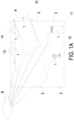
- the present disclosure provides an indoor air pollution prevention system includes at least one indoor field unit A, an outdoor field unit C and a cloud computing service device B.
- the indoor field unit A is a space surrounded and isolated by a plurality of partitions.
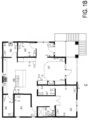
- the indoor field unit A is an indoor space formed in a general residential building, and includes a living room A1, a bedroom A2, family room A3, an office A4, a conference room A5, a tea room A6, dressing room A7, a kitchen A8, and a bathroom A9 (as shown in FIG. 1B ).
- the indoor field unit A of the indoor air pollution prevention system of the present invention includes all spaces separated in the indoor.
- the indoor field unit A is an indoor space formed in a public building, including gymnasium, a concert hall, a theater, an exhibition space, a hospital spaces, an airport space and a station spaces, but limited thereto.
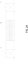
- the air guiding device 1 has the functions of pumping or supplying air to transport gas in two directions.
- the direction of the airflow path for pumping and supplying is indicated by the arrow for illustration (such as the direction indicated by the arrow shown in FIG. 2A ).
- the air guiding device 1 is disposed at the front side of the filter screen 2, or the air guiding device 1 is disposed at the rear side of the filter screen 2.
- the air guiding devices 1 are arranged at the front and rear sides of the filtering screen 2.
- the air guiding device 1 can be an air purifier (including a circulating fan purifier), a fan 12, a range hood 13, an exhaust fan 14 or a fresh air fan 15.
- the outdoor field unit C includes at least one gas detector 3 disposed therein.
- the gas detector 3 in the outdoor field unit C is used for detecting a characteristic, a concentration and a location of an air pollution, and outputting to form air pollution data.
- Each of the plurality of gas detectors 3 disposed in the indoor field unit A and the outdoor field unit C detects a characteristic, a concentration and a location of an air pollution, and outputs to form air pollution data detected in the indoor field unit A and the outdoor field unit C.
- the filter screen 2 filters the air pollution in air passing therethrough.
- the air guiding device 1 guides the air pollution to pass through the filter screen 2 for filtering and removal.
- the cloud computing service device B receives the air pollution data detected in the indoor field unit A and the outdoor field unit C, stores the air pollution data in an air pollution database, implements an artificial intelligence calculation to determine the location of the air pollution, and issuing a control command to the air guiding device to control an activation operation of the air guiding device 1. Whereby, a directional airflow is generated, and the air containing the air pollution is guided quickly to the filter screen 2 for filtering and removal to reach a gas state of complete purification.
- the air pollution is at least one selected from the group consisting of particulate matter, carbon monoxide, carbon dioxide, ozone, sulfur dioxide, nitrogen dioxide, lead, total volatile organic compounds (TVOC), formaldehyde, bacteria, fungi, virus and a combination thereof.
- the cloud computing server device B includes a wireless network cloud computing service module B1, a cloud control service unit B2, a device management unit B3 and an application program unit B4.
- the wireless network cloud computing service module B1 receives the air pollution data detected in the indoor field unit A, receives the communication information of the air guiding device 1 and transmits the control commands.
- the wireless network cloud computing service module B1 receives the air pollution data detected in the indoor field unit A and transmits the air pollution data to the cloud control service unit B2 to store and form an air pollution database.
- An artificial intelligence calculation is implemented to determine the location of the air pollution through the air pollution database comparison, so that the control commend is transmitted to the wireless network cloud computing service module B1, and then transmitted to the air guiding device 1 to control the actuation operation through the wireless network cloud computing service module B1.
- the device management unit B3 receives the communication information of the air guiding device 1 through the wireless network cloud computing service module B1 to manage the user login and device binding.
- the device management information can be provided to the application program unit B4 for system control and management, and the application program unit B4 can also display and inform the air pollution data obtained by the cloud control service unit B2.
- the user can know the real-time status of air pollution removal through the mobile phone or the communication device.
- the user can control the operation of the indoor air pollution prevention system through the application program unit B4 of the mobile phone or the communication device.
- the plurality of gas detectors 3 are disposed in the indoor field unit A to detect the characteristics and the concentrations of the air pollution.
- the indoor field unit A is one selected from the group consisting of a living room A1, a bedroom A2, a family room A3, an office A4, a conference room A5, a tea room A6, a dressing room A7, a gymnasium, a concert hall, a theater, an exhibition space, a hospital space, an airport space, a station space and a combination thereof.
- the cloud computing service device B receives and compares the air pollution data detected by the plurality of gas detectors 3 in the indoor field unit A and the outdoor field unit C.
- the cloud computing service device B issues the control command to the air guiding device 1 for the activation operation, the air in the outdoor field unit C is introduced through the filter screen 2 for filtering and enters into the indoor field unit A, and the air pollution in the indoor field unit is A guided to the filter screen 2 for filtering and removal to the outdoor field unit C, thereby the air in the indoor field unit A is exchanged to reach the gas state of complete purification.
- the air guiding device 1 is a fresh air fan 15 (gas exchanging device), and the filter screen 2 is directly disposed within the air guiding device 1 to filter the air pollution.
- the indoor field unit A is one selected from the group consisting of a living room A1, a bedroom A2, a family room A3, an office A4, a conference room A5, a tea room A6, a dressing room A7, a gymnasium, a concert hall, a theater, an exhibition space, a hospital space, an airport space, a station space and a combination thereof.
- the cloud computing service device B receives and compares at least two or more of the air pollution data detected by the plurality of gas detectors 3 in the indoor field unit A, intelligently calculates to position the location of the air pollution in the indoor field unit A, and intelligently selects to issue the control command to the air guiding device 1.
- the air guiding device 1 closest to the location of the air pollution is enabled for the activation operation firstly, then other air guiding devices 1 are enabled for the activation operation, and the directional airflow is generated to guide the air pollution to the filter screen 2 for filtering and removal.
- the air pollution in the indoor field unit A is cleaned quickly to reach the gas state of complete purification.
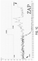
- the gas detector 3 installed in the indoor field unit A for detecting suspended particles PM2.5 is taken as an example. Before the user activates the indoor air pollution prevention system at 7:40, the PM2.5 value of suspended particulate matter detected in the indoor field unit A is similar to the PM2.5 value of suspended particulate matter detected in the outdoor field unit C.
- the gas detector 3 in the indoor field unit A detects the air pollution data of suspended particulate matter PM2.5
- the cloud computing service device B receives and compares at least two or more of the air pollution data detected by the plurality of gas detectors 3 in the indoor field unit A, intelligently calculates to position the location of the air pollution in the indoor field unit A, and intelligently selects to issue the control command to the air guiding device 1.
- the value of the air pollution data detected in the entire indoor field unit A is dropped rapidly, and the effect of air pollution complete purification is maintained thereafter.
- the air guiding device 1 in the indoor field unit A can be an air purifier 11 (including a circulating fan purifier) or a fan 12, and the filter screen 2 can also be directly disposed within the air guiding device 1 to filter the air pollution.
- the indoor field unit A is a kitchen field unit A8, and the cloud computing service device B receives and compares the air pollution data detected by the gas detector 3 in the indoor field unit A.
- the control command is intelligently selected and issued to the air guiding device 1 for the activation operation, and the air pollution is quickly guided to the filter screen 2 for filtering and removal, so that the air pollution in the indoor field unit A is cleaned to reach the gas state of complete purification.
- the air guiding device 1 in the indoor field unit A is a range hood 13.
- the filter screen 2 is directly disposed within the air guiding device 1 to the filter air pollution.
- the gas detector 3 is also directly disposed within the air guiding device 1.
- the indoor field unit A is a bathroom field unit A9
- the cloud computing service device B receives and compares the air pollution data detected by the gas detector 3 in the indoor field unit A.
- the control command is intelligently selected and issued to the air guiding device 1 for the activation operation, and the air pollution is quickly guided to the filter screen 2 for filtering and removal, so that the air pollution in the indoor field unit A is cleaned to reach the gas state of complete purification, and the temperature and the humidity of the indoor field unit A are controlled.
- the air guiding device 1 in the indoor field unit A is an exhaust fan 14, the filter screen 2 is directly disposed within the air guiding device 1 to filter the air pollution, and the gas detector 3 is also directly disposed on the air guiding device 1.
- the safety detection value includes at least one selected from the group consisting of a concentration of PM2.5 which is less than 15 ⁇ g/m 3 , a concentration of carbon dioxide which is less than 1000 ppm, a concentration of total volatile organic compounds (TVOC) which is less than 0.56 ppm, a concentration of formaldehyde (HCHO) which is less than 0.08 ppm, a colony-forming unit of bacteria which is less than 1500 CFU/m 3 , a colony-forming unit of fungi which is less than 1000 CFU/m 3 , a concentration of sulfur dioxide which is less than 0.075 ppm, a concentration of nitrogen dioxide which is less than 0.1 ppm, a concentration of carbon monoxide which is less than 9 ppm, a concentration of ozone which is less than 0.06 ppm, and a concentration of lead which is less than 0.15 ⁇ g/m 3 .
- a concentration of PM2.5 which is less than 15 ⁇ g/m 3
- a concentration of carbon dioxide which is
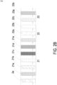
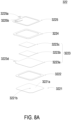
- the filter screen 2 is a filter screen to clean the air pollution through a physical way of blocking and absorbing.
- the filter screen is a high efficiency particulate air (HEPA) filter screen 2a, which is configured to absorb the chemical smoke, the bacteria, the dust particles and the pollen contained in the air pollution, so that the air pollution introduced is filtered and purified to achieve the effect of filtering and purification.
- the filter screen 2 is a high HEPA filter screen 2a coated with decomposition layer 21 to clean the air pollution through a chemical way.
- the decomposition layer 21 includes an activated carbon 21a configured to remove organic and inorganic substances in air pollution, and remove colored and odorous substances.
- the decomposition layer 21 includes a cleansing factor containing chlorine dioxide layer 21b configured to inhibit viruses, bacteria, fungi, influenza A, influenza B, enterovirus and norovirus in the air pollution, and the inhibition ratio can reach 99% and more, thereby reducing the cross-infection of viruses.
- the decomposition layer 21 includes an herbal protective layer 21c extracted from ginkgo and Japanese Rhus chinensis configured to resist allergy effectively and destroy a surface protein of influenza virus (such as H1N1 influenza virus) passing therethrough.
- the decomposition layer 21 includes a silver ion 21d configured to inhibit viruses, bacteria and fungi contained in the air pollution.
- the decomposition layer 21 includes a zeolite 21e configured to remove ammonia nitrogen, heavy metals, organic pollutants, Escherichia coli, phenol, chloroform and anionic surfactants.
- the filter screen 2 is a high HEPA filter screen 2a combined with a light irradiation element 22 to clean the air pollution through a chemical way.
- the light irradiation element 22 is a photo-catalyst unit including a photo catalyst 22a and an ultraviolet lamp 22b.
- the photo catalyst 22a When the photo catalyst 22a is irradiated by the ultraviolet lamp 22b, the light energy is converted into the chemical energy, thereby decomposes harmful gases and disinfects bacteria contained in the air pollution, so as to achieve the effects of filtering and purifying.
- the light irradiation element 22 is a photo-plasma unit including a nanometer irradiation tube 22c.
- the introduced air pollution is irradiated by the nanometer irradiation tube 22c
- the oxygen molecules and water molecules contained in the air pollution are decomposed into high oxidizing photo-plasma, and an ion flow capable of destroying organic molecules is generated.
- the filter screen 2 is a high HEPA filter screen 2a combined with a decomposition unit 23 to clean the air pollution through a chemical way.
- the decomposition unit is a negative ion unit 23a with s a dust collecting plate. It makes the suspended particles in the air pollution to carry with positive charge and adhered to the dust collecting plate carry with negative charges, so as to achieve the effects of filtering and purifying.
- the decomposition unit is a plasma ion unit 23b.
- the oxygen molecules and water molecules contained in the air pollution are decomposed into positive hydrogen ions (H + ) and negative oxygen ions (O 2- ) by the plasma ion.
- the substances attached with water around the ions are adhered on the surface of viruses and bacteria and converted into OH radicals with extremely strong oxidizing power, thereby removing hydrogen (H) from the protein on the surface of viruses and bacteria, and thus decomposing (oxidizing) the protein, so as to filter the introduced air pollution and achieve the effects of filtering and purifying.
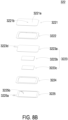
- the gas detector 3 includes a gas detection module disposed thereon.
- the gas detection module includes a controlling circuit board 31, a gas detection main part 32, a microprocessor 33 and a communicator 34.
- the gas detection main part 32, the microprocessor 33 and the communicator 34 are integrally packaged on the controlling circuit board 31 and electrically connected to the controlling circuit board 31.
- the microprocessor 33 and the communicator 34 are disposed on the controlling circuit board 31, and the microprocessor 33 controls the detection of the gas detection main part 32.
- the gas detection main part 32 detects the air pollution and outputs a detection signal
- the microprocessor 33 receives and processes the detection signal to generate air pollution data and provides the air pollution data to the communicator 34 for a wireless communication transmission externally to the cloud computing service device B.
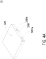
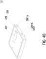
- the gas detection main part 32 includes a base 321, a piezoelectric actuator 322, a driving circuit board 323, a laser component 324, a particulate sensor 325, and an outer cover 326.
- the base 321 includes a first surface 3211, a second surface 3212, a laser loading region 3213, a gas-inlet groove 3214, a gas-guiding-component loading region 3215 and a gas-outlet groove 3216.
- the first surface 3211 and the second surface 3212 are two surfaces opposite to each other.
- the laser loading region 3213 is hollowed out from the first surface 3211 toward the second surface 3212.
- the outer cover 326 covers the base 321 and includes a side plate 3261.
- the side plate 3261 has an inlet opening 3261a and an outlet opening 3261b.
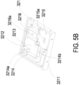
- the gas-inlet groove 3214 is concavely formed from the second surface 3212 and disposed adjacent to the laser loading region 3213.
- the gas-inlet groove 3214 includes a gas-inlet 3214a and two lateral walls.
- the gas-inlet 3214a is in communication with an environment outside the base 321, and is spatially corresponding in position to an inlet opening 3261a of the outer cover 326.
- Two transparent windows 3214b are opened on the two lateral walls of the gas-inlet groove 3214 and are in communication with the laser loading region 3213. Therefore, the first surface 3211 of the base 321 is covered and attached by the outer cover 326, and the second surface 3212 is covered and attached by the driving circuit board 323, so that an inlet path is defined by the gas-inlet groove 3214.
- the first section 3216b is concavely formed out from the first surface 3211 in a region spatially corresponding to a vertical projection area of the gas-guiding-component loading region 3215.
- the second section 3216c is hollowed out from the first surface 3211 to the second surface 3212 in a region where the first surface 3211 is extended from the vertical projection area of the gas-guiding-component loading region 3215.
- the first section 3216b and the second section 3216c are connected to form a stepped structure.
- the first section 3216b of the gas-outlet groove 3216 is in communication with the ventilation hole 3215a of the gas-guiding-component loading region 3215
- the second section 3216c of the gas-outlet groove 3216 is in communication with the gas-outlet 3216a.
- the laser component 324 and the particulate sensor 325 are disposed on and electrically connected to the driving circuit board 323 and located within the base 321.
- the driving circuit board 323 is intentionally omitted.
- the laser component 324 is accommodated in the laser loading region 3213 of the base 321
- the particulate sensor 325 is accommodated in the gas-inlet groove 3214 of the base 321 and is aligned to the laser component 324.
- the laser component 324 is spatially corresponding to the transparent window 3214b, therefore, a light beam emitted by the laser component 324 passes through the transparent window 3214b and is irradiated into the gas-inlet groove 3214.
- a light beam path emitted from the laser component 324 passes through the transparent window 3214b and extends in an orthogonal direction perpendicular to the gas-inlet groove 3214.
- a projecting light beam emitted from the laser component 324 passes through the transparent window 3214b and enters the gas-inlet groove 3214 to irradiate the suspended particles contained in the gas passing through the gas-inlet groove 3214.
- the scattered light spots are received and calculated by the particulate sensor 325 to obtain the gas detection data.
- the gas sensor 327 is positioned and disposed on the driving circuit board 323, electrically connected to the driving circuit board 323, and accommodated in the gas-outlet groove 3216, so as to detect the air pollution introduced into the gas-outlet groove 3216.
- the piezoelectric actuator 322 is accommodated in the square-shaped gas-guiding-component loading region 3215 of the base 321.
- the gas-guiding-component loading region 3215 of the base 321 is in fluid communication with the gas-inlet groove 3214.
- the piezoelectric actuator 322 is enabled, the gas in the gas-inlet groove 3214 is inhaled by the piezoelectric actuator 322, so that the gas flows into the piezoelectric actuator 322, and is transported into the gas-outlet groove 3216 through the ventilation hole 3215a of the gas-guiding-component loading region 3215.
- the driving circuit board 323 covers the second surface 3212 of the base 321, and the laser component 324 is disposed on the driving circuit board 323, and is electrically connected to the driving circuit board 323.
- the particulate sensor 325 is also disposed on the driving circuit board 323 and electrically connected to the driving circuit board 323.
- the inlet opening 3261a is spatially corresponding to the gas-inlet 3214a of the base 321
- the outlet opening 3261b is spatially corresponding to the gas-outlet 3216a of the base 321.
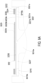
- the piezoelectric actuator 322 includes a gas-injection plate 3221, a chamber frame 3222, an actuator element 3223, an insulation frame 3224 and a conductive frame 3225.
- the gas-injection plate 3221 is made by a flexible material and includes a suspension plate 3221a and a hollow aperture 3221b.
- the suspension plate 3221a is a sheet structure and is permitted to undergo a bending deformation.
- the shape and the size of the suspension plate 3221a are accommodated in the inner edge of the gas-guiding-component loading region 3215, but not limited thereto.
- the hollow aperture 3221b passes through a center of the suspension plate 3221a, so as to allow the gas to flow therethrough.
- the shape of the suspension plate 3221a is selected from the group consisting of a square, a circle, an ellipse, a triangle and a polygon, but not limited thereto.
- the chamber frame 3222 is carried and stacked on the gas-injection plate 3221.
- the shape of the chamber frame 3222 is corresponding to the gas-injection plate 3221.
- the actuator element 3223 is carried and stacked on the chamber frame 3222.
- a resonance chamber 3226 is collaboratively defined by the actuator element 3223, the chamber frame 3222 and the suspension plate 3221a and is formed between the actuator element 3223, the chamber frame 3222 and the suspension plate 3221a.
- the insulation frame 3224 is carried and stacked on the actuator element 3223 and the appearance of the insulation frame 3224 is similar to that of the chamber frame 3222.
- the conductive frame 3225 is carried and stacked on the insulation frame 3224, and the appearance of the conductive frame 3225 is similar to that of the insulation frame 3224.
- the conductive frame 3225 includes a conducting pin 3225a and a conducting electrode 3225b.
- the conducting pin 3225a is extended outwardly from an outer edge of the conductive frame 3225
- the conducting electrode 3225b is extended inwardly from an inner edge of the conductive frame 3225.
- the actuator element 3223 further includes a piezoelectric carrying plate 3223a, an adjusting resonance plate 3223b and a piezoelectric plate 3223c.
- the piezoelectric carrying plate 3223a is carried and stacked on the chamber frame 3222.
- the adjusting resonance plate 3223b is carried and stacked on the piezoelectric carrying plate 3223a.
- the piezoelectric plate 3223c is carried and stacked on the adjusting resonance plate 3223b.
- the adjusting resonance plate 3223b and the piezoelectric plate 3223c are accommodated in the insulation frame 3224.
- the conducting electrode 3225b of the conductive frame 3225 is electrically connected to the piezoelectric plate 3223c.
- the piezoelectric carrying plate 3223a and the adjusting resonance plate 3223b are made by a conductive material.
- the piezoelectric carrying plate 3223a includes a piezoelectric pin 3223d.
- the piezoelectric pin 3223d and the conducting pin 3225a are electrically connected to a driving circuit (not shown) of the driving circuit board 323, so as to receive a driving signal, such as a driving frequency and a driving voltage.
- a circuit is formed by the piezoelectric pin 3223d, the piezoelectric carrying plate 3223a, the adjusting resonance plate 3223b, the piezoelectric plate 3223c, the conducting electrode 3225b, the conductive frame 3225 and the conducting pin 3225a for transmitting the driving signal.
- the insulation frame 3224 is insulated between the conductive frame 3225 and the actuator element 3223, so as to avoid the occurrence of a short circuit. Thereby, the driving signal is transmitted to the piezoelectric plate 3223c.
- the piezoelectric plate 3223c After receiving the driving signal such as the driving frequency and the driving voltage, the piezoelectric plate 3223c deforms due to the piezoelectric effect, and the piezoelectric carrying plate 3223a and the adjusting resonance plate 3223b are further driven to generate the bending deformation in the reciprocating manner.
- the adjusting resonance plate 3223b is located between the piezoelectric plate 3223c and the piezoelectric carrying plate 3223a and served as a cushion between the piezoelectric plate 3223c and the piezoelectric carrying plate 3223a.
- the vibration frequency of the piezoelectric carrying plate 3223a is adjustable.
- the thickness of the adjusting resonance plate 3223b is greater than the thickness of the piezoelectric carrying plate 3223a, and the vibration frequency of the actuator element 3223 can be adjusted by adjusting the thickness of the adjusting resonance plate 3223b.
- the gas-injection plate 3221, the chamber frame 3222, the actuator element 3223, the insulation frame 3224 and the conductive frame 3225 are stacked and positioned in the gas-guiding-component loading region 3215 sequentially, so that the piezoelectric actuator 322 is supported and positioned in the gas-guiding-component loading region 3215.
- a plurality of clearances 3221c are defined between the suspension plate 3221a of the gas-injection plate 3221 and an inner edge of the gas-guiding-component loading region 3215 for gas flowing therethrough.
- a flowing chamber 3227 is formed between the gas-injection plate 3221 and the bottom surface of the gas-guiding-component loading region 3215.
- the flowing chamber 3227 is in communication with the resonance chamber 3226 between the actuator element 3223, the chamber frame 3222 and the suspension plate 3221a through the hollow aperture 3221b of the gas-injection plate 3221.
- the gas is inhaled through the gas-inlet 3214a on the outer cover 326, flows into the gas-inlet groove 3214 of the base 321 through the gas-inlet 3214a, and is transported to the position of the particulate sensor 325.
- the piezoelectric actuator 322 is enabled continuously to inhale the gas into the inlet path, and facilitate the gas outside the gas detection module to be introduced rapidly, flow stably, and transported above the particulate sensor 325.
- a projecting light beam emitted from the laser component 324 passes through the transparent window 3214b to irritate the suspended particles contained in the gas flowing above the particulate sensor 325 in the gas-inlet groove 3214.
- the scattered light spots are received and calculated by the particulate sensor 325 for obtaining related information about the sizes and the concentration of the suspended particles contained in the gas.
- the gas above the particulate sensor 325 is continuously driven and transported by the piezoelectric actuator 322, flows into the ventilation hole 3215a of the gas-guiding-component loading region 3215, and is transported to the gas-outlet groove 3216.
- the gas is continuously transported into the gas-outlet groove 3216 by the piezoelectric actuator 322, and thus the gas in the gas-outlet groove 3216 is pushed to discharge through the gas-outlet 3216a and the outlet opening 3261b.
- the gas detector 3 of the present disclosure not only includes particulate sensor 325 for detecting the particulate matters (e.g., PM1 PM2.5 or PM10) in the gas, but also includes a gas sensor for detecting the gas characteristics of the introduced gas, for example, to determine whether the gas is formaldehyde, ammonia, carbon monoxide, carbon dioxide, oxygen, ozone, or the like. Therefore, in one or some embodiments, the gas detector 3 of the present disclosure further includes the gas sensor 327 positioned and disposed on the driving circuit board 323, electrically connected to the driving circuit board 323, and accommodated in the gas-outlet groove 3216, so as to detect the concentration or the characteristics of volatile organic compounds contained in the gas exported from the gas outlet path.
- particulate sensor 325 for detecting the particulate matters (e.g., PM1 PM2.5 or PM10) in the gas
- a gas sensor for detecting the gas characteristics of the introduced gas, for example, to determine whether the gas is formaldehyde, ammonia, carbon monoxide, carbon
- the present disclosure provides an indoor air pollution prevention system.
- the indoor air pollution prevention system of the present disclosure includes a plurality of gas detectors, at least one filter screen and at least one air guiding device arranged in various indoor fields.
- the gas detector determines a characteristic, a concentration and a location of an air pollution, and outputs to form air pollution data
- the cloud computing service device receives the air pollution data detected in the indoor field unit and the outdoor field unit, stores the air pollution data in an air pollution database, implements an artificial intelligence calculation to determine the location of the air pollution, and issues a control command to the air guiding device to control an activation operation of the air guiding device, so that a directional airflow is generated to quickly guide the air pollution to the filter screen for filtering and removal completely.
- the indoor air pollution treatment of positioning the air pollution-guiding the air pollution-purifying the air pollution completely is formed, and a clean and safe breathing gas state is achieved.
- the present disclosure includes the industrial applicability and the inventive steps.
Landscapes
- Engineering & Computer Science (AREA)
- Chemical & Material Sciences (AREA)
- Combustion & Propulsion (AREA)
- Mechanical Engineering (AREA)
- General Engineering & Computer Science (AREA)
- Chemical Kinetics & Catalysis (AREA)
- Health & Medical Sciences (AREA)
- General Chemical & Material Sciences (AREA)
- Life Sciences & Earth Sciences (AREA)
- Analytical Chemistry (AREA)
- General Health & Medical Sciences (AREA)
- Human Computer Interaction (AREA)
- Public Health (AREA)
- Epidemiology (AREA)
- Veterinary Medicine (AREA)
- Biomedical Technology (AREA)
- Animal Behavior & Ethology (AREA)
- Environmental & Geological Engineering (AREA)
- Oil, Petroleum & Natural Gas (AREA)
- Physics & Mathematics (AREA)
- Signal Processing (AREA)
- Immunology (AREA)
- Computer Networks & Wireless Communication (AREA)
- Pathology (AREA)
- General Physics & Mathematics (AREA)
- Molecular Biology (AREA)
- Biochemistry (AREA)
- Fuzzy Systems (AREA)
- Mathematical Physics (AREA)
- Ventilation (AREA)
- Air Conditioning Control Device (AREA)
- Disinfection, Sterilisation Or Deodorisation Of Air (AREA)
Applications Claiming Priority (1)
| Application Number | Priority Date | Filing Date | Title |
|---|---|---|---|
| TW112125910A TWI905522B (zh) | 2023-07-11 | 2023-07-11 | 室內空污防治系統 |
Publications (2)
| Publication Number | Publication Date |
|---|---|
| EP4491960A1 true EP4491960A1 (fr) | 2025-01-15 |
| EP4491960B1 EP4491960B1 (fr) | 2026-02-18 |
Family
ID=91481759
Family Applications (1)
| Application Number | Title | Priority Date | Filing Date |
|---|---|---|---|
| EP24181405.2A Active EP4491960B1 (fr) | 2023-07-11 | 2024-06-11 | Système de prévention de pollution d'air intérieur |
Country Status (5)
| Country | Link |
|---|---|
| US (1) | US20250020354A1 (fr) |
| EP (1) | EP4491960B1 (fr) |
| JP (1) | JP2025013187A (fr) |
| CN (1) | CN119309272A (fr) |
| TW (1) | TWI905522B (fr) |
Citations (4)
| Publication number | Priority date | Publication date | Assignee | Title |
|---|---|---|---|---|
| US11480351B2 (en) * | 2019-08-29 | 2022-10-25 | Lg Electronics Inc. | Air purifier and operating method of the same |
| WO2022266451A1 (fr) * | 2021-06-17 | 2022-12-22 | Research Products Corporation | Système de commande de la qualité de l'air d'un bâtiment entier |
| TWI796113B (zh) * | 2022-01-24 | 2023-03-11 | 研能科技股份有限公司 | 防治空污抽風機 |
| US11635221B2 (en) * | 2020-06-01 | 2023-04-25 | Energy Cloud Inc. | Cloud based HVAC management apparatus and system for air purification, indoor air quality monitoring, and methods for implementing the same |
Family Cites Families (12)
| Publication number | Priority date | Publication date | Assignee | Title |
|---|---|---|---|---|
| JP3408547B2 (ja) * | 1991-02-21 | 2003-05-19 | 松下電器産業株式会社 | 空気調和装置 |
| WO2006001368A1 (fr) * | 2004-06-24 | 2006-01-05 | Max Co., Ltd | Machine d'épuration d'air et système d'épuration d'air |
| JP2011002166A (ja) * | 2009-06-19 | 2011-01-06 | Panasonic Corp | 空気清浄システム |
| KR102439718B1 (ko) * | 2014-07-11 | 2022-09-02 | 지-콘 메뉴팩츄어링 인코포레이티드 | 유틸리티를 청정실, 격리 또는 봉쇄 큐비클, 포드 또는 모듈에 공급하는 모듈형 부품 |
| TWI620902B (zh) * | 2017-04-21 | 2018-04-11 | Chen Bing Jian | Outdoor air purification filter |
| CN207881086U (zh) * | 2018-02-09 | 2018-09-18 | 北京东方计量测试研究所 | 混风式新风净化系统 |
| EP3767402B1 (fr) * | 2019-07-19 | 2023-08-23 | Siemens Schweiz AG | Système de chauffage, de ventilation et de climatisation |
| CN114646115B (zh) * | 2020-12-21 | 2024-07-02 | 研能科技股份有限公司 | 智能室内空气污染防治解决方法 |
| TWI778474B (zh) * | 2020-12-21 | 2022-09-21 | 研能科技股份有限公司 | 室內氣體汙染過濾方法 |
| TWI839611B (zh) * | 2021-04-29 | 2024-04-21 | 研能科技股份有限公司 | 室內空汙防治系統 |
| JP7845643B2 (ja) * | 2021-11-30 | 2026-04-14 | シー・エイチ・シー・システム株式会社 | 施設内環境の遠隔集中制御システム |
| CN217383194U (zh) * | 2022-01-10 | 2022-09-06 | 陆逸远 | 一种工厂车间新风系统 |
-
2023
- 2023-07-11 TW TW112125910A patent/TWI905522B/zh active
-
2024
- 2024-01-08 CN CN202410027050.2A patent/CN119309272A/zh active Pending
- 2024-03-07 US US18/598,409 patent/US20250020354A1/en active Pending
- 2024-06-07 JP JP2024093342A patent/JP2025013187A/ja active Pending
- 2024-06-11 EP EP24181405.2A patent/EP4491960B1/fr active Active
Patent Citations (4)
| Publication number | Priority date | Publication date | Assignee | Title |
|---|---|---|---|---|
| US11480351B2 (en) * | 2019-08-29 | 2022-10-25 | Lg Electronics Inc. | Air purifier and operating method of the same |
| US11635221B2 (en) * | 2020-06-01 | 2023-04-25 | Energy Cloud Inc. | Cloud based HVAC management apparatus and system for air purification, indoor air quality monitoring, and methods for implementing the same |
| WO2022266451A1 (fr) * | 2021-06-17 | 2022-12-22 | Research Products Corporation | Système de commande de la qualité de l'air d'un bâtiment entier |
| TWI796113B (zh) * | 2022-01-24 | 2023-03-11 | 研能科技股份有限公司 | 防治空污抽風機 |
Also Published As
| Publication number | Publication date |
|---|---|
| TW202503206A (zh) | 2025-01-16 |
| EP4491960B1 (fr) | 2026-02-18 |
| CN119309272A (zh) | 2025-01-14 |
| US20250020354A1 (en) | 2025-01-16 |
| TWI905522B (zh) | 2025-11-21 |
| JP2025013187A (ja) | 2025-01-24 |
Similar Documents
| Publication | Publication Date | Title |
|---|---|---|
| US12013151B2 (en) | Method of filtering indoor air pollution | |
| US12435899B2 (en) | Air purifier for preventing air pollution | |
| US12485376B2 (en) | Exhaust fan for preventing air pollution | |
| EP4299996B1 (fr) | Contrôleur central pour le nettoyage complet de la pollution de l'air intérieur | |
| EP4445989A1 (fr) | Procédé de purification de pollution de l'air dans un espace intérieur à un niveau proche de zéro | |
| EP4446664A1 (fr) | Purificateur d'air | |
| US20240003563A1 (en) | Method for detecting and cleaning indoor air pollution | |
| US20250067459A1 (en) | Indoor air cleaning system | |
| EP4491960B1 (fr) | Système de prévention de pollution d'air intérieur | |
| EP4491959A2 (fr) | Système de prévention de pollution d'air intérieur | |
| US11988393B2 (en) | Range hood for preventing air pollution | |
| EP4498080A1 (fr) | Système de prévention de pollution d'air intérieur | |
| US20250155132A1 (en) | Air pollution prevention system for kitchen unit in indoor field | |
| US20250067451A1 (en) | Indoor air cleaning system | |
| US20250129963A1 (en) | Indoor air cleaning system | |
| US20250075929A1 (en) | Indoor air cleaning system | |
| US20250060121A1 (en) | Air pollution prevention system for bathroom space | |
| EP4299995A1 (fr) | Conception de la localisation et du nettoyage complet de la pollution de l'air intérieur | |
| US20250164137A1 (en) | Indoor air cleaning system with disconnection detecting and preventing mechanism | |
| EP4446665A1 (fr) | Ventilateur d'échappement | |
| US20260049728A1 (en) | Positive pressure control method of indoor air cleaning network mechanism system | |
| EP4446659A1 (fr) | Hotte de cuisine | |
| US20260022850A1 (en) | Indoor air cleaning network mechanism system | |
| US20260022851A1 (en) | Mountable fan filter assembly | |
| US20260022845A1 (en) | Mountable gas exchange device |
Legal Events
| Date | Code | Title | Description |
|---|---|---|---|
| PUAI | Public reference made under article 153(3) epc to a published international application that has entered the european phase |
Free format text: ORIGINAL CODE: 0009012 |
|
| STAA | Information on the status of an ep patent application or granted ep patent |
Free format text: STATUS: THE APPLICATION HAS BEEN PUBLISHED |
|
| AK | Designated contracting states |
Kind code of ref document: A1 Designated state(s): AL AT BE BG CH CY CZ DE DK EE ES FI FR GB GR HR HU IE IS IT LI LT LU LV MC ME MK MT NL NO PL PT RO RS SE SI SK SM TR |
|
| STAA | Information on the status of an ep patent application or granted ep patent |
Free format text: STATUS: REQUEST FOR EXAMINATION WAS MADE |
|
| 17P | Request for examination filed |
Effective date: 20250708 |
|
| GRAP | Despatch of communication of intention to grant a patent |
Free format text: ORIGINAL CODE: EPIDOSNIGR1 |
|
| STAA | Information on the status of an ep patent application or granted ep patent |
Free format text: STATUS: GRANT OF PATENT IS INTENDED |
|
| INTG | Intention to grant announced |
Effective date: 20251020 |
|
| GRAS | Grant fee paid |
Free format text: ORIGINAL CODE: EPIDOSNIGR3 |
|
| GRAA | (expected) grant |
Free format text: ORIGINAL CODE: 0009210 |
|
| STAA | Information on the status of an ep patent application or granted ep patent |
Free format text: STATUS: THE PATENT HAS BEEN GRANTED |
|
| AK | Designated contracting states |
Kind code of ref document: B1 Designated state(s): AL AT BE BG CH CY CZ DE DK EE ES FI FR GB GR HR HU IE IS IT LI LT LU LV MC ME MK MT NL NO PL PT RO RS SE SI SK SM TR |
|
| REG | Reference to a national code |
Ref country code: CH Ref legal event code: F10 Free format text: ST27 STATUS EVENT CODE: U-0-0-F10-F00 (AS PROVIDED BY THE NATIONAL OFFICE) Effective date: 20260218 Ref country code: GB Ref legal event code: FG4D |
|
| P01 | Opt-out of the competence of the unified patent court (upc) registered |
Free format text: CASE NUMBER: UPC_APP_0002184_4491960/2026 Effective date: 20260121 |
|
| REG | Reference to a national code |
Ref country code: DE Ref legal event code: R096 Ref document number: 602024002608 Country of ref document: DE |
|
| REG | Reference to a national code |
Ref country code: IE Ref legal event code: FG4D |