EP4491966A1 - Vorrichtung zum einstellen eines luftvolumenstroms - Google Patents
Vorrichtung zum einstellen eines luftvolumenstroms Download PDFInfo
- Publication number
- EP4491966A1 EP4491966A1 EP23184608.0A EP23184608A EP4491966A1 EP 4491966 A1 EP4491966 A1 EP 4491966A1 EP 23184608 A EP23184608 A EP 23184608A EP 4491966 A1 EP4491966 A1 EP 4491966A1
- Authority
- EP
- European Patent Office
- Prior art keywords
- throttle
- air
- flow
- flow element
- trailing edge
- Prior art date
- Legal status (The legal status is an assumption and is not a legal conclusion. Google has not performed a legal analysis and makes no representation as to the accuracy of the status listed.)
- Pending
Links
Images


Classifications
-
- F—MECHANICAL ENGINEERING; LIGHTING; HEATING; WEAPONS; BLASTING
- F24—HEATING; RANGES; VENTILATING
- F24F—AIR-CONDITIONING; AIR-HUMIDIFICATION; VENTILATION; USE OF AIR CURRENTS FOR SCREENING
- F24F13/00—Details common to, or for air-conditioning, air-humidification, ventilation or use of air currents for screening
- F24F13/02—Ducting arrangements
- F24F13/06—Outlets for directing or distributing air into rooms or spaces, e.g. ceiling air diffuser
- F24F13/062—Outlets for directing or distributing air into rooms or spaces, e.g. ceiling air diffuser having one or more bowls or cones diverging in the flow direction
-
- F—MECHANICAL ENGINEERING; LIGHTING; HEATING; WEAPONS; BLASTING
- F24—HEATING; RANGES; VENTILATING
- F24F—AIR-CONDITIONING; AIR-HUMIDIFICATION; VENTILATION; USE OF AIR CURRENTS FOR SCREENING
- F24F13/00—Details common to, or for air-conditioning, air-humidification, ventilation or use of air currents for screening
- F24F13/08—Air-flow control members, e.g. louvres, grilles, flaps or guide plates
- F24F13/10—Air-flow control members, e.g. louvres, grilles, flaps or guide plates movable, e.g. dampers
-
- F—MECHANICAL ENGINEERING; LIGHTING; HEATING; WEAPONS; BLASTING
- F24—HEATING; RANGES; VENTILATING
- F24F—AIR-CONDITIONING; AIR-HUMIDIFICATION; VENTILATION; USE OF AIR CURRENTS FOR SCREENING
- F24F11/00—Control or safety arrangements
- F24F11/70—Control systems characterised by their outputs; Constructional details thereof
- F24F11/72—Control systems characterised by their outputs; Constructional details thereof for controlling the supply of treated air, e.g. its pressure
- F24F11/74—Control systems characterised by their outputs; Constructional details thereof for controlling the supply of treated air, e.g. its pressure for controlling air flow rate or air velocity
-
- F—MECHANICAL ENGINEERING; LIGHTING; HEATING; WEAPONS; BLASTING
- F24—HEATING; RANGES; VENTILATING
- F24F—AIR-CONDITIONING; AIR-HUMIDIFICATION; VENTILATION; USE OF AIR CURRENTS FOR SCREENING
- F24F11/00—Control or safety arrangements
- F24F11/89—Arrangement or mounting of control or safety devices
-
- F—MECHANICAL ENGINEERING; LIGHTING; HEATING; WEAPONS; BLASTING
- F24—HEATING; RANGES; VENTILATING
- F24F—AIR-CONDITIONING; AIR-HUMIDIFICATION; VENTILATION; USE OF AIR CURRENTS FOR SCREENING
- F24F13/00—Details common to, or for air-conditioning, air-humidification, ventilation or use of air currents for screening
- F24F13/08—Air-flow control members, e.g. louvres, grilles, flaps or guide plates
- F24F13/10—Air-flow control members, e.g. louvres, grilles, flaps or guide plates movable, e.g. dampers
- F24F13/12—Air-flow control members, e.g. louvres, grilles, flaps or guide plates movable, e.g. dampers built up of sliding members
-
- F—MECHANICAL ENGINEERING; LIGHTING; HEATING; WEAPONS; BLASTING
- F24—HEATING; RANGES; VENTILATING
- F24F—AIR-CONDITIONING; AIR-HUMIDIFICATION; VENTILATION; USE OF AIR CURRENTS FOR SCREENING
- F24F7/00—Ventilation
- F24F7/04—Ventilation with ducting systems, e.g. by double walls; with natural circulation
Definitions
- the present invention relates to a device for adjusting an air volume flow, in particular an air supply valve.
- Air distribution networks are used in buildings in particular for ventilation and sometimes for air conditioning. Controlled residential and office ventilation systems are now sophisticated systems that use central or decentralized ventilation units.
- the wall, ceiling or floor openings of a building have air outlets with inserts that are connected to the air distribution network.
- air outlets change the shape of the air flow and/or regulate the air volume flow. They are called supply air valves or exhaust air valves depending on the direction of the flow into or out of the room. They limit the cross-section in the air duct, whereby the size of this limitation can be selected using throttles.
- WO 2022/101056 A1 discloses an air volume throttle valve with air guide bodies in the form of blades of a rotor.
- the air guide bodies are each formed from a first and a second air guide unit, which can be rotated relative to one another, so that the distance between the air guide bodies and thus the flow-through cross-section of an air duct can be changed.
- This device enables the free flow cross-section to be changed while the position of the narrowest flow cross-section remains the same. This makes it easier to control the valve.
- the device according to the invention for adjusting an air volume flow in particular in an air distribution network, has a flow-through air channel which defines a longitudinal central axis.
- the device has a throttle in order to change a size of a flow-through cross section of the air channel.
- a flow element is arranged in the air channel, wherein the flow element has a jacket whose cross section increases in a first direction away from the throttle.
- the jacket has an end region facing away from the throttle, which inclines in a second direction and forms a trailing edge, wherein the second direction is opposite to the first direction.
- the air flow is applied to the wall or ceiling early on, i.e. close to the supply air valve. This prevents backflow areas. This means that there is hardly any dirt or dust deposits on the wall or ceiling.
- the cross-section of the trailing edge is wedge-shaped.
- This upwardly inclined trailing edge can be used with throttles of different designs.
- the trailing edge is preferably designed to be circumferential. It preferably has no interruptions that could disrupt the homogeneous distribution of the outflowing air.
- the flow element is designed to be air-impermeable, so that all the air that is passed through the device flows along the outer surface of the flow element.
- the flow element is bell-shaped.
- the bell widens towards the exit, i.e. towards the inside of the building.
- the casing or at least the end area with the trailing edge is rotationally symmetrical.
- the air flow is optimized when the casing is curved inwards except for the end area facing away from the throttle.
- the outer surface of the casing is preferably flat, ie without elevations and depressions.
- the air flow can therefore spread unhindered.
- the device has a circumferential surface opposite the end region of the casing, which together with the end region forms the exit region, i.e. an exit opening of the air duct. If this circumferential surface also inclines in the second direction, the flow behavior is further optimized.
- the surrounding surface is flat in order to have no interfering elements.
- the outlet opening is preferably designed as an annular channel which is defined by the end region forming the trailing edge and by the circumferential surface, wherein the annular channel has a cross-sectional area which remains constant in the direction of the longitudinal central axis. This leads to a further optimization of the flow behavior.
- a further optimization occurs when the inclination of the end area in the area of the trailing edge and the inclination of the surrounding surface are the same.
- the device has a housing in which the throttle and the flow element are arranged.
- the peripheral surface is a flange of the housing, wherein the flange is designed to rest against a wall. This facilitates the installation of the device in a wall opening and also enables the outlet opening of the air duct to be arranged close to the ceiling or the wall.
- This local arrangement is also facilitated if the second direction leads towards the wall when the device is installed in the wall opening.
- the assembly and adjustment of the device is facilitated if the flow element is hollow and can be closed with a lid.
- the position of the flow element relative to the housing or relative to the wall surface does not change when the throttle setting is changed.
- the cross-section of the outlet channel or the outlet opening of the air channel preferably does not change when the throttle setting is changed.
- Figure 1 shows a valve V according to the invention, which is installed in a wall opening 10 of a wall 11.
- the wall opening 10 is preferably part of an air distribution network of a building.
- the terms "bottom” and “top” used in this text refer to the installation position of the valve in the wall opening of a building ceiling. If the wall opening is in another wall of a building, these terms are to be interpreted accordingly.
- the valve V is preferably a supply air valve which directs air from an air distribution network through a wall opening into a building room. However, it can also be used as an exhaust air valve which directs air from the building room into the wall opening 10.
- valve V is described as a supply air valve, although its function is identical to that of an exhaust air valve.
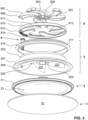
- the valve V has, as shown in the Figures 2 to 4 can be clearly seen, a housing 2, an inner flow element 3, a pivot pin 4, a cover 5 and a throttle 6.
- the housing 2 is preferably designed in two parts. It preferably has a round cross-section.
- a first housing part 20 has a hollow, circular-cylindrical base body 200, the lowermost end of which forms a radially outwardly projecting flange 201. With this flange 201, the valve V rests against the building wall 11, as shown in Figure 1
- the first flange 201 is preferably rigid and serves as a stop when inserting the valve V into the wall opening 10, as shown in Figure 1 can be seen. It forms a closure to cover irregularities in the surrounding wall 11.
- the first flange 201 also serves to delimit an outlet opening 80 of an air duct 8, as described further down in the text. For this purpose, the first flange 201 has an incline towards the wall 11.
- the incline is preferably achieved by continuously thinning the flange 201 towards its outer peripheral edge.
- the downward-facing surface of the flange 201 is flat, ie without elevations or depressions.
- the flange 201 is circumferential, closed and preferably without interruptions. Possible interruptions are holes for screwing the housing 2 into the wall opening 10.
- the housing 2 is fixed in the wall opening in another way.
- the base body 200 has a first step 202 and a second step 203 on its outer circumference.
- a circumferential upper end face 204 is preferably flat.
- the upper end face 204 has a recess 205 for the passage of the pivot pin 4.
- a third throttle part 22 is formed, which is described further below in the text together with a first and a second throttle part 60, 61 of the throttle 6.
- a second housing part 21 has a narrow, hollow cylindrical or ring-shaped base body 210. It is surrounded by a radially projecting second flange 211.
- the second flange 211 is preferably designed as a flexible sealing and/or clamping ring It serves to seal and detachably fix the valve V in the wall opening 10, as shown in Figure 1 can be seen.
- the wall opening 10 preferably has a round cross-section for this purpose.
- the second flange 211 can be sprayed on, formed in one piece or connected to the second base body 210 in another way.
- the second housing part 21 surrounds the upper region of the first housing part 20. It rests on the first step 202 and preferably extends to the second step 203.
- the housing 2 encloses a central air channel which defines a longitudinal central axis L and radial directions.
- the inner flow element 3 is arranged in the housing 2 and extends downwards towards the interior of the building, as shown in Figure 1 can be seen.
- the inner flow element 3 is preferably hollow and can be closed at the bottom with the cover 5.
- the flow element 3 is closed at the top except for a through opening 33 for the passage of the pivot pin 4.
- the flow element 3 is preferably designed to be substantially rotationally symmetrical. It has a bell-shaped configuration, with a cross-section that widens downwards and a casing 30 that curves inwards. The flow element 3 preferably extends to the outer edge of the first flange 201 or beyond.
- the flow element 3 is held fixed in the first housing part 20, preferably with a bayonet lock or with another detachable and re-establishable connection. These coupling elements are preferably arranged in the region of the longitudinal center axis L. In Figure 2 a second coupling element 220 of the first housing part 20 and a matching coupling element 34 of the flow element 3 are clearly visible. It is a plug-in and rotating connection in the form of a bayonet lock.
- a flow channel here called air channel 8
- air channel 8 is formed between the first housing part 20 and the flow element 3. It leads from the wall opening 10 through the throttle 6 and through an annular gap between the first flange 201 and the casing 30 of the flow element 3 into the Building interior.
- the annular gap forms the outlet opening 80 of the air duct 8.
- the gap is usually always the same size, regardless of the adjustability of the throttle 6 described further down in the text.
- the outflow cross-section of the valve V therefore remains the same even if the setting of the throttle 6 changes, and thus if the flow-through cross-section of the throttle 6 changes.
- the trailing edge 31 of the flow element 3 optimizes the outflow behavior, as shown in Figure 1 can be seen.
- the trailing edge 31 is formed by an end region of the casing 30 which is spaced apart from the throttle 6. It is circumferential and preferably uninterrupted.
- the casing 30 is flat at least in this end region, but preferably over the entire surface facing the throttle 6. The air flow flows over this surface.
- the outflow behavior is further optimized thanks to the first flange 201, which also inclines upwards.
- the inclinations are identical, so that the outlet opening has a constant cross-section in the direction of the longitudinal center axis L.
- the shell 30 has a slightly larger diameter than the second flange 201, as shown in Figure 1 is clearly visible.
- the flow element 3 has a lower annular edge which forms a flat lower end face 32 against which the cover 5 rests.
- the annular edge surrounds an inlet opening which leads into a hollow interior.
- the cover 5 has a base plate 50 with a preferably flat lower end face 51. It can be attached to and removed from the flow element 3 preferably without tools. Magnets are arranged in both components for this purpose.
- the magnets of the flow element 3 are in Figure 2 They are marked with the reference number 35.
- the magnets of the cover 5 are in the Figures 2 and 4 They are marked with the reference number 52.
- the flow element 3 is preferably arranged in a fixed position with respect to the housing 2 and is preferably not adjustable at least in the direction of the longitudinal center axis L, i.e. axially.
- the throttle 6 is arranged in the upper area of the valve V. Any throttle can be used. Preferably, it has adjustable elements for selectively narrowing the central air channel. In other embodiments, the throttle not adjustable or it only has an open and a closed position.
- the throttle shown here has a variable cross-section that determines the air flow that can flow through the central air duct. This variable cross-section determined by the throttle 6 is referred to in this text as the flow-through cross-section.
- the cross-section of the central air duct is preferably no longer adjustable. However, it is not necessarily the same size everywhere.
- This subsequent cross-section is preferably formed by the distance between the preferably inwardly curved inner wall of the housing 2 and the casing 30 of the flow element 3.
- the throttle 6 consists of three components.
- the first throttle part 60 is connected in a rotationally fixed manner to the housing 2 and/or to the third throttle part 22.
- the third throttle part 22 is formed in one piece with the housing 2 and is also rotationally fixed with respect to the first throttle part 60.
- the second throttle part 61 is arranged between the first and third throttle parts 60, 22 and can be pivoted or rotated about the longitudinal center axis L.
- the third throttle part 22 is also an independent component, which is preferably connected to the housing 2 in a rotationally fixed manner.
- the second throttle part 61 is preferably also designed with an optimized design of its inflow or outflow surface.
- the first throttle part 60 has locking elements in the form of rotor-like first vanes 601, which extend outwards from a common central part. This central part forms a first coupling element 600. In this example, five first vanes 601 are present. However, three, four, six or any other number of vanes can also be used.
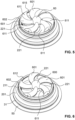
- hooks or lugs 602 are used for mounting exhaust air filters and/or hoods. They rest, for example, on the upper face of the second throttle part 61. This is shown in the Figures 1 , 5 and 6 clearly visible.
- the first wings 601 widen towards their free ends. Preferably, all wings 601 are of the same shape and size. The first wings 601 are curved in the radial direction. Preferably, the area left free between two wings 601 corresponds to the area of one wing 601.
- the upper flow surfaces of the first wings 601 are preferably curved so that an aerodynamically favorable body is formed.
- the third throttle part 22 has blocking elements in the form of third wings 221, which form geometric counterparts to the first wings 601. In this example, they are thus also designed to be curved in the radial direction. These third wings 221 do not end freely, but rather their peripheral ends are formed on the inner wall of the first housing part 20. Their central ends merge in one piece into a middle part, which is formed by the second coupling element 220.
- the first coupling element 600 has downwardly projecting hooks 603 which engage in receiving openings of the second coupling element 220. In this way, the first throttle part 60 is connected in a rotationally fixed manner to the third throttle part 22 and also to the housing 2.
- the first and third wings 601, 221 are aligned with one another.
- the first and third wings 601, 221 lie congruently on top of one another.
- the free surface of the third wings 221 is also curved.
- This outflow surface is thus also aerodynamically optimized.
- the flow surfaces of the first and third wings 601, 221 are identically curved, so that the valve V forms the same inflow and outflow surfaces and can therefore be used equally for supply and exhaust air.
- the intermediate second throttle part 61 has an outer ring 610.
- Inwardly projecting locking elements in the form of second wings 611 are formed on the upper end of the ring 610.
- the outer ring 610 rests with the free lower end of its casing on the second step 203 of the housing 2. It also rests with its inwardly projecting, upper peripheral edge on the upper face 204 of the housing 2. This is shown in the Figures 1 , 2 , 3 and 4 clearly visible.
- the ring 610 and thus the second throttle part 61 is rotatable about the longitudinal central axis L, wherein it is guided during rotation by the base body 210 of the second housing part 21 and is fixed in its axial position by the lugs 602 of the first throttle part 60.
- the second wings 611 of the second coupling part 61 end freely towards the longitudinal center axis L. They are also curved, and preferably have the same bending radii as the first and third wings 601, 221. There are the same number of second wings 611 as there are first and third wings 601, 221. There are preferably the same number of second wings 611 as there are first and third wings 601, 221.
- the second wings 611 can be flat. Other designs are possible.
- the second throttle disc 61 thus forms a flat disc with a circumferential guide casing, wherein the disc is arranged between the flat end faces of the first and third wings 601, 221 and can be rotated relative to these.
- the rotation is preferably continuous. In other embodiments it is step-by-step.
- optical, haptic and/or acoustic means are preferably present to indicate to the user that discrete positions of the throttle disc 61 have been reached. Furthermore, such means protect against unintentional adjustment.
- the rotation of the throttle disk 61 serves to adjust the valve V. This is preferably done manually. Alternatively or additionally, however, it can also be motor-driven.
- the adjustment can preferably also be carried out when the valve V is already mounted in the wall opening 10. This can be carried out in a simple embodiment by removing the flow element 3 and the cover 5. In a preferred embodiment, which is shown here as an example, only the cover 5 is removed, if at all.
- the through opening 33 in the casing 31 of the flow element 3 allows access to the adjustment element, here to the rotary pin 4. This is shown in the Figures 1 to 4 clearly visible.
- the pivot pin 4 has a pin 40, a head 41 designed as a gear and a knurling 42 on the circumference of the free end of the pin 40.
- the knurling 42 increases the grip when the pivot pin 4 is turned by hand, without using any other tools. However, tools can also be used for this purpose.
- the pivot pin 4 passes through the recess 205 of the first housing part 20, as shown in the Figures 1 and 2 can be seen.
- the head 41 rests on the first housing part 20.
- the second throttle part 61 has a toothing 612 in an area of its inner circumference.
- the gear of the head 41 engages in this toothing 612 thanks to the recess 205.
- the second throttle part 61 can be rotated about the longitudinal center axis L. The position of the second wings 611 relative to the first and third wings 601, 221 can thus be adjusted manually.
- the first housing part 20 has a scale 222 next to the recess, which interacts with a reference 614 of the second throttle part 61. This allows the setting of the throttle to be noted and the rotational position of the blades relative to each other to be recognized. This is shown in the Figures 2 and 3 recognizable.
- the device according to the invention for adjusting a volume flow optimizes the outflow behavior.
Landscapes
- Engineering & Computer Science (AREA)
- Chemical & Material Sciences (AREA)
- Combustion & Propulsion (AREA)
- Mechanical Engineering (AREA)
- General Engineering & Computer Science (AREA)
- Physics & Mathematics (AREA)
- Fluid Mechanics (AREA)
- Air-Flow Control Members (AREA)
Abstract
Eine Vorrichtung zum Einstellen eines Luftvolumenstroms, insbesondere in einem Luftverteilnetz, weist einen durchströmbaren Luftkanal auf, der eine Längsmittelachse definiert. Die Vorrichtung weist eine Drossel (6) auf, um eine Grösse eines durchströmbaren Querschnitts des Luftkanals zu verändern. Ein Strömungselement (3) ist im Luftkanal angeordnet, wobei das Strömungselement (3) einen Mantel (30) aufweist, dessen Querschnitt sich in einer ersten Richtung von der Drossel (6) weg vergrössert. Der Mantel (30) weist einen der Drossel (6) abgewandten Endbereich auf, der sich in eine zweite Richtung neigt und der eine Abströmkante (31) bildet, wobei die zweite Richtung der ersten Richtung entgegen gesetzt ist. Die Vorrichtung optimiert das Ausströmverhalten.
Description
- Die vorliegende Erfindung betrifft eine Vorrichtung zum Einstellen eines Luftvolumenstroms, insbesondere ein Zuluftventil.
- Luftverteilnetze sind insbesondere in Gebäuden für die Be- und Entlüftung und teilweise für die Klimatisierung der Räume im Einsatz. Kontrollierte Wohnungs- und Bürolüftungsanlagen sind mittlerweile ausgereifte Systeme, die zentrale oder dezentrale Lüftungsgeräte verwenden.
- Die Wand-, Decken- oder Bodenöffnungen eines Gebäudes weisen Luftdurchlässe mit Einsätzen auf, die mit dem Luftverteilnetz verbunden sind. Derartige Luftdurchlässe verändern die Form des Luftstroms und/oder sie regulieren den Luftvolumenstrom. Sie werden je nach Richtung der Strömung in den Raum oder aus dem Raum als Zuluftventile oder Abluftventile bezeichnet. Sie begrenzen den Querschnitt im Luftkanal, wobei die Grösse dieser Begrenzung mittels Drosseln wählbar ist.
- Leider lassen sich derartige Zuluft- und Abluftventile im eingebauten Zustand oft nicht oder nur mit einem relativ grossen Aufwand einstellen. Ein weiterer Nachteil ist, dass einzelne Bauteile des Ventils je nach Einstellgrad des Ventils unterschiedlich weit in den Raum hineinragen, sich von der Gebäudewand abheben und das optische Erscheinungsbild des Raums beeinträchtigen.
- Zuluftventile, d.h. Ventile, durch die Luft in einen Raum strömt, weisen zudem oft den Nachteil auf, dass sie die ausströmende Luft nicht gleichmässig verteilen. Eine sitzende oder liegende Person, die der ausströmenden Luft unmittelbar ausgesetzt ist, kann dies als unangenehm empfinden. Ferner ergeben sich dadurch Streifen von Schmutzablagerungen, die besser sichtbar sind als eine gleichmässige Ablagerung. Ein inhomogenes Ausströmverhalten führt zudem zu erhöhter Geräuschbildung.
- Ein weiterer Nachteil ist, dass Abluftventile, d.h. Ventile, durch die Luft aus einem Raum strömt, oft eine andere Form aufweisen als Zuluftventile. Dies führt zu einem eher unruhigen Erscheinungsbild im Raum.
-
WO 2022/101056 A1 offenbart ein Luftvolumen-Drosselventil mit Luftleitkörpern in Form von Flügeln eines Rotors. Die Luftleitkörper sind aus je einer ersten und einer zweiten Luftleiteinheit gebildet, die sich relativ zueinander verdrehen lassen, so dass der Abstand zwischen den Luftleitkörpern und somit der durchströmbare Querschnitt eines Luftkanals veränderbar ist. Diese Vorrichtung ermöglicht eine Veränderung des freien Strömungsquerschnitts bei gleichbleibender Stelle des engsten Strömungsquerschnitts. Dies erleichtert die Regelung des Ventils. - Es ist deshalb eine Aufgabe der Erfindung, eine verbesserte Vorrichtung zum Einstellen eines Volumenstroms zu schaffen.
- Diese Aufgabe löst eine Vorrichtung mit den Merkmalen des Anspruchs 1.
- Die erfindungsgemässe Vorrichtung zum Einstellen eines Luftvolumenstroms, insbesondere in einem Luftverteilnetz, weist einen durchströmbaren Luftkanal auf, der eine Längsmittelachse definiert. Die Vorrichtung weist eine Drossel auf, um eine Grösse eines durchströmbaren Querschnitts des Luftkanals zu verändern. Ein Strömungselement ist im Luftkanal angeordnet, wobei das Strömungselement einen Mantel aufweist, dessen Querschnitt sich in einer ersten Richtung von der Drossel weg vergrössert. Der Mantel weist einen der Drossel abgewandten Endbereich auf, der sich in eine zweite Richtung neigt und der eine Abströmkante bildet, wobei die zweite Richtung der ersten Richtung entgegen gesetzt ist.
- Die Anordnung des Endbereichs mit der Abströmkante und des zweiten Flansches führt dazu, dass aus dem Ventil ausströmende Luft in Richtung Decke bzw. Wand gelenkt wird.
- Der Luftstrom legt sich bereits früh, d.h. nahe beim Zuluftventil, an die Wand bzw. an die Decke an. Dadurch werden Rückströmgebiete vermieden. Es gibt somit kaum Schmutz- oder Staubablagerungen an der Wand bzw. der Decke.
- Dank der geschwungenen Form des Ausgangsbereichs des Luftkanals, erzeugt durch die geneigte Abströmkante, werden Wirbel gebildet. Die Wirbel mischen sich mit dem nachfolgenden Luftstrom, der durch die Drossel strahlenförmig ausgerichtet ist. Dadurch wird eine homogene Abströmung über 360° ermöglicht.
- Vorzugsweise ist der Querschnitt der Abströmkante keilförmig.
- Diese nach oben geneigte Abströmkante lässt sich mit in unterschiedlich ausgebildeten Drosseln verwenden.
- Vorzugsweise ist die Abströmkante umlaufend ausgebildet. Sie weist vorzugsweise keine Unterbrechungen auf, die die homogene Verteilung der ausströmenden Luft unterbrechen könnten.
- Vorzugsweise ist das Strömungselement luftundurchlässig ausgebildet, so dass die gesamte Luft, die durch die Vorrichtung durchgeführt wird, entlang der Mantelfläche des Strömungselements strömt.
- Vorzugsweise ist das Strömungselement glockenförmig ausgebildet. Vorzugsweise erweitert sich die Glocke zum Ausgang, d.h. zur Gebäudeinnenseite hin.
- Vorzugsweise ist der Mantel oder mindestens der Endbereich mit der Abströmkante, rotationssymmetrisch ausgebildet. Die Luftströmung ist optimiert, wenn der Mantel bis auf den der Drossel abgewandten Endbereich nach innen gewölbt ist.
- Die äussere Oberfläche des Mantels ist vorzugsweise flach, d.h. ohne Erhebungen und Vertiefungen. Der Luftstrom kann sich dadurch unbehindert ausbreiten. Vorzugsweise sind zumindest im Ausgangbereich des Luftkanals, d.h. im Bereich der Abströmkante, keinerlei Schikanen oder Hindernissse vorhanden, die in den Luftkanal hineinragen.
- Vorzugsweise weist die Vorrichtung eine dem Endbereich des Mantels gegenüberliegende umlaufende Fläche auf, die gemeinsam mit dem Endbereich den Ausgangsbereich, d.h. eine Ausgangsöffnung des Luftkanals, bildet. Wenn diese umlaufende Fläche sich ebenfalls in die zweite Richtung neigt, ist das Strömungsverhalten weiter optimiert.
- Vorzugsweise ist die umlaufende Fläche flach ausgebildet, um keinerlei Störelemente aufzuweisen.
- Die Ausgangsöffnung ist vorzugsweise als ringförmiger Kanal ausgebildet, der durch den die Abströmkante ausbildenden Endbereich und durch die umlaufende Fläche definiert ist, wobei der ringförmige Kanal eine in Richtung der Längsmittelachse gleichbleibende Querschnittfläche aufweist. Dies führt zu einer weiteren Optimierung des Strömungsverhaltens.
- Eine weitere Optimierung liegt vor, wenn die Neigung des Endbereichs im Bereich der Abströmkante und die Neigung der umlaufenden Fläche gleich sind.
- In bevorzugten Ausführungsformen weist die Vorrichtung ein Gehäuse auf, in welchem die Drossel und das Strömungselement angeordnet sind. Die umlaufende Fläche ist ein Flansch des Gehäuses, wobei der Flansch zur Anlage an eine Wand ausgebildet ist. Dies erleichtert die Montage der Vorrichtung in einer Wandöffnung und ermöglicht zudem eine der Decke bzw. der Wand nahe Anordnung der Ausgangsöffnung des Luftkanals.
- Diese ortsnahe Anordnung ist zudem erleichtert, wenn im in der Wandöffnung eingebauten Zustand der Vorrichtung die zweite Richtung zur Wand hin führt.
- Die Montage und Einstellung der Vorrichtung ist erleichtert, wenn das Strömungselement hohl ausgebildet ist und mit einem Deckel verschliessbar ist.
- Vorzugsweise verändert sich die Lage des Strömungselements relativ zum Gehäuse bzw. relativ zur Wandoberfläche bei Veränderung der Einstellung der Drossel nicht. Ebenso verändert sich vorzugsweise der Querschnitt des Ausgangskanals bzw. der Ausgangsöffnung des Luftkanals bei Veränderung der Einstellung der Drossel nicht.
- Weitere Ausführungsformen sind in den abhängigen Ansprüchen angegeben.
- Bevorzugte Ausführungsformen der Erfindung werden im Folgenden anhand der Zeichnungen beschrieben, die lediglich zur Erläuterung dienen und nicht einschränkend auszulegen sind. In den Zeichnungen zeigen:
- Figur 1
- einen Längsschnitt durch eine erfindungsgemässe Vorrichtung, eingebaut in einer Wandöffnung;
- Figur 2
- eine Explosionsdarstellung der Vorrichtung gemäss
Figur 1 von oben; - Figur 3
- eine erste Explosionsdarstellung der Vorrichtung gemäss
Figur 1 von unten; - Figur 4
- eine zweite Explosionsdarstellung der Vorrichtung gemäss
Figur 1 von unten; - Figur 5
- eine perspektivische Ansicht der Vorrichtung gemäss
Figur 1 von oben in teilweise geschlossener Position der Drossel und - Figur 6
- eine perspektivische Ansicht der Vorrichtung gemäss
Figur 5 in einer vollständig offenen Position der Drossel. -
Figur 1 zeigt ein erfindungsgemässes Ventil V, das in einer Wandöffnung 10 einer Wand 11 eingebaut ist. Die Wandöffnung 10 ist vorzugsweise Teil eines Luftverteilnetzes eines Gebäudes. Die in diesem Text verwendeten Begriffe "unten" und "oben" beziehen sich auf die Einbaulage des Ventils in der Wandöffnung einer Gebäudedecke. Befindet sich die Wandöffnung in einer anderen Wand eines Gebäudes, sind diese Begriffe entsprechend auszulegen. - Das Ventil V ist ein vorzugsweise ein Zuluftventil, welches Luft von einem Luftverteilnetz durch eine Wandöffnung in einen Gebäuderaum hineinleitet. Es lässt sich jedoch auch als Abluftventil einsetzen, welches Luft aus dem Gebäuderaum in die Wandöffnung 10 leitet.
- Nachfolgend wird das Ventil V als Zuluftventil beschrieben, wobei es in seiner Funktion als Abluftventil identisch ausgebildet ist.
- Das Ventil V weist, wie in den
Figuren 2 bis 4 gut erkennbar ist, ein Gehäuse 2, ein inneres Strömungselement 3, einen Drehstift 4, einen Deckel 5 und eine Drossel 6 auf. - Das Gehäuse 2 ist vorzugsweise zweiteilig ausgebildet. Es weist vorzugsweise einen runden Querschnitt auf. Ein erstes Gehäuseteil 20 weist einen hohlen, kreiszylinderförmigen Grundkörper 200 auf, dessen unterstes Ende einen radial nach aussen vorstehenden Flansch 201 ausbildet. Mit diesem Flansch 201 liegt das Ventil V an der Gebäudewand 11 an, wie in
Figur 1 erkennbar ist. Der erste Flansch 201 ist vorzugsweise steif ausgebildet und dient als Anschlag bei Einschieben des Ventils V in die Maueröffnung 10, wie inFigur 1 erkennbar ist. Er bildet einen Abschluss zur Überdeckung von Unregelmässigkeiten in der umliegenden Wand 11. Der erste Flansch 201 dient ferner Begrenzung einer Ausgangsöffnung 80 eines Luftkanals 8, wie weiter unten im Text beschrieben ist. Der erste Flansch 201 weist hierfür eine Neigung hin zur Wand 11 auf. Vorzugsweise wird die Neigung durch stetige Verdünnung des Flansches 201 zu seiner äusseren umlaufenden Kante hin erreicht. Die nach unten gerichtete Oberfläche des Flansches 201 ist flach, d.h. ohne Erhebungen oder Vertiefungen, ausgebildet. Der Flansch 201 ist umlaufend, geschlossen und vorzugsweise ohne Unterbrechungen ausgebildet. Mögliche Unterbrechungen sind Löcher zum Festschrauben des Gehäuses 2 in der Wandöffnung 10. Vorzugsweise ist das Gehäuse 2 jedoch auf andere Art und Weise in der Wandöffnung fixiert. - Der Grundkörper 200 weist an seinem äusseren Umfang eine erste Stufe 202 und eine zweite Stufe 203 auf. Eine umlaufende obere Stirnfläche 204 ist vorzugsweise plan ausgebildet. Die obere Stirnfläche 204 weist eine Ausnehmung 205 zur Durchführung des Drehstiftes 4 auf.
- Im oberen Bereich des ersten Gehäuseteils 20 ist ein drittes Drosselteil 22 ausgebildet, das weiter unten im Text gemeinsam mit einem ersten und einem zweiten Drosselteil 60, 61 der Drossel 6 beschrieben ist.
- Ein zweites Gehäuseteil 21 weist einen schmalen, hohlzylinderförmigen bzw. ringförmigen Grundkörper 210 auf. Er ist von einem radial vorstehenden zweiten Flansch 211 umgeben. Der zweite Flansch 211 ist vorzugsweise als flexibler Dichtungs- und/oder Klemmring ausgebildet. Er dient zur Dichtung und lösbaren Befestigung des Ventil V in der Wandöffnung 10, wie in
Figur 1 erkennbar ist. Die Wandöffnung 10 weist hierfür vorzugsweise einen runden Querschnitt auf. Der zweite Flansch 211 kann aufgespritzt sein, einteilig angeformt sein oder auf andere Art und Weise mit dem zweiten Grundkörper 210 verbunden sein. - Das zweite Gehäuseteil 21 umgibt den oberen Bereich des ersten Gehäuseteils 20. Es liegt auf der ersten Stufe 202 auf und erstreckt sich vorzugsweise bis zur zweiten Stufe 203.
- Das Gehäuse 2 umschliesst einen zentralen Luftkanal, der eine Längsmittelachse L und radiale Richtungen definiert.
- Im Gehäuse 2 ist das innere Strömungselement 3 angeordnet, das sich nach unten zum Gebäudeinnenraum hin erstreckt, wie in
Figur 1 erkennbar ist. Das innere Strömungselement 3 ist vorzugsweise hohl ausgebildet und gegen unten mit dem Deckel 5 verschliessbar. Das Strömungselement 3 ist bis auf eine Durchgangsöffnung 33 zur Durchführung des Drehstifts 4 nach oben geschlossen ausgebildet. - Das Strömungselement 3 ist vorzugsweise im Wesentlichen rotationssymmetrisch ausgebildet. Es weist eine glockenförmige Gestalt auf, mit einem sich nach unten erweiterndem Querschnitt und nach innen gewölbten Mantel 30. Das Strömungselement 3 erstreckt sich vorzugsweise bis zum äusseren Rand des ersten Flansches 201 oder darüber hinaus.
- Das Strömungselement 3 ist im ersten Gehäuseteil 20 fixiert gehalten, vorzugsweise mit einem Bajonettverschluss oder mit einer anderen lösbaren und wieder herstellbaren Verbindung. Diese Kopplungselemente sind vorzugsweise im Bereich der Längsmittelachse L angeordnet. In
Figur2 ist ein zweites Kopplungselement 220 des ersten Gehäuseteils 20 sowie ein dazu passendes Kopplungselement 34 des Strömungselements 3 gut erkennbar. Es ist eine Steck- und Drehverbindung in Form eines Bajonettverschlusses. - Wie in
Figur 1 erkennbar ist, ist zwischen dem ersten Gehäuseteil 20 und dem Strömungselement 3 ein Strömungskanalausgebildet, hier Luftkanal 8 genannt. Er führt von der Wandöffnung 10 durch die Drossel 6 und durch einen ringförmigen Spalt zwischen dem ersten Flansch 201 und dem Mantel 30 des Strömungselements 3 in den Gebäudeinnenraum. Der ringförmige Spalt bildet die Ausgangsöffnung 80 des Luftkanals 8. Der Spalt ist üblicherweise stets gleich gross, unabhängig von der weiter unten im Text beschriebenen Einstellbarkeit der Drossel 6. Der Ausströmungsquerschnitt des Ventils V bleibt somit auch bei Veränderung der Einstellung der Drossel 6 gleich, und somit bei Veränderung des durchströmbaren Querschnitts der Drossel 6. - Eine nach oben gebogene Abströmkante 31 des Strömungselements 3 optimiert das Abströmungsverhalten, wie in
Figur 1 erkennbar ist. Die Abströmkante 31 sich durch einen der Drossel 6 beabstandeten Endbereich des Mantels 30 gebildet. Sie ist umlaufend und vorzugsweise ununterbrochen. Der Mantel 30 ist mindestens in diesem Endbereich, vorzugsweise jedoch über die gesamte, der Drossel 6 zugewandten Oberfläche flach ausgebildet. Diese Oberfläche wird vom Luftstrom überströmt. - Das Abströmungsverhalten ist dank des sich ebenfalls nach oben neigenden ersten Flansches 201 weiter optimiert. Vorzugsweise sind die Neigungen identisch, so dass die Ausgangsöffnung in Richtung der Längsmittelachse L einen gleichbleibenden Querschnitt aufweist.
- Vorzugsweise weist der Mantel 30 einen leicht grösseren Durchmesser auf als der zweite Flansch 201, wie dies in
Figur 1 gut erkennbar ist. - Das Strömungselement 3 weist einen unteren ringförmigen Rand auf, der eine plane untere Stirnfläche 32 ausbildet, an die der Deckel 5 anliegt. Der ringförmige Rand umgibt eine Eingangsöffnung, die in einen hohlen Innenraum führt. Der Deckel 5 weist eine Grundplatte 50 mit einer vorzugsweise planen unteren Stirnfläche 51 auf. Er lässt sich vorzugsweise werkzeugfrei an das Strömungselement 3 anbringen und von ihm entfernen. Hierzu sind Magnete in beiden Bauteilen angeordnet. Die Magnete des Strömungselements 3 sind in
Figur 2 erkennbar. Sie sind mit dem Bezugszeichen 35 versehen. Die Magnete des Deckels 5 sind in denFiguren 2 und4 erkennbar. Sie sind mit den Bezugszeichen 52 versehen. - Das Strömungselement 3 ist vorzugsweise lagefixiert bezüglich des Gehäuses 2 angeordnet und vorzugsweise mindestens in Richtung der Längsmittelachse L, d.h. axial, nicht verstellbar.
- Im oberen Bereich des Ventils V ist die Drossel 6 angeordnet. Es lassen sich beliebige Drosseln verwenden. Vorzugsweise weist sie einstellbare Elemente zur wahlweisen Verengung des zentralen Luftkanals auf. In anderen Ausführungsformen ist die Drossel nicht einstellbar oder sie weist lediglich eine offene und eine geschlossene Stellung auf.
- Die hier dargestellte Drossel weist einen veränderbaren Querschnitt auf, der den Luftstrom bestimmt, der durch den zentralen Luftkanal fliessen kann. Dieser von der Drossel 6 bestimmte veränderbare Querschnitt ist in diesem Text als durchströmbarer Querschnitt bezeichnet.
- In Strömungsrichtung der Drossel 6 nachfolgend, d.h. zum Gebäudeinnenraum hingewandt, ist der Querschnitt des zentralen Luftkanals vorzugsweise nicht mehr einstellbar. Er ist jedoch nicht zwingend überall gleich gross. Dieser nachfolgende Querschnitt ist vorzugsweise durch den Abstand zwischen der vorzugsweise nach innen gewölbten Innenwandung des Gehäuses 2 und dem Mantel 30 des Strömungselements 3 gebildet.
- Die Drossel 6 besteht in dieser Ausführungsform aus drei Bauteilen. Das erste Drosselteil 60 ist drehfest mit dem Gehäuse 2 und/oder mit dem dritten Drosselteil 22 verbunden. Das dritte Drosselteil 22 ist einteilig mit dem Gehäuse 2 ausgebildet und ebenfalls drehfest bezüglich dem ersten Drosselteil 60. Das zweite Drosselteil 61 ist zwischen dem ersten und dem dritten Drosselteil 60, 22 angeordnet und um die Längsmittelachse L schwenk- oder drehbar.
- In anderen Ausführungsformen ist auch das dritte Drosselteil 22 ein eigenständiges Bauteil, das vorzugsweise drehfest mit dem Gehäuse 2 verbunden ist. In anderen Ausführungsformen sind lediglich das erste und das zweite Drosselteil 60, 61 vorhanden, jedoch kein drittes Drosselteil 22, bzw. es sind lediglich das zweite und das dritte Drosselteil 61, 22 vorhanden, jedoch kein erstes Drosselteil 60. Sind nur zwei Drosselteile vorhanden, so ist vorzugsweise auch das zweite Drosselteil 61 mit einer optimierten Ausbildung seiner An- oder Abströmfläche ausgebildet.
- Das erste Drosselteil 60 weist Sperrelemente in Form von rotorähnlichen ersten Flügeln 601 auf, die sich von einem gemeinsamen Mittelteil nach aussen erstrecken. Dieses Mittelteil bildet ein erstes Kopplungselement 600. In diesem Beispiel sind fünf erste Flügel 601 vorhanden. Es lassen sich jedoch auch drei, vier, sechs oder eine andere Anzahl Flügel verwenden.
- An den Stirnseiten der freien Enden der ersten Flügel 601 sind Haken oder Nasen 602 angeformt. Sie dienen der Montage von Abluftfiltern und/oder Hauben. Sie liegen beispielsweise auf der oberen Stirnfläche des zweiten Drosselteils 61 auf. Dies ist in den
Figuren 1 ,5 und 6 gut erkennbar. - Die ersten Flügel 601 erweitern sich zu ihren freien Enden hin. Vorzugsweise sind alle Flügel 601 gleich geformt und gleich gross. Die ersten Flügel 601 sind in radialer Richtung gebogen ausgebildet. Vorzugsweise entspricht die zwischen zwei Flügeln 601 freigelassene Fläche der Fläche eines Flügels 601.
- Die oberen Anströmflächen der ersten Flügel 601 sind vorzugsweise gebogen ausgebildet, so dass ein aerodynamisch günstiger Körper ausgebildet ist.
- Das dritte Drosselteil 22 weist Sperrelemente in Form von dritten Flügeln 221 auf, die geometrische Gegenstücke zu den ersten Flügeln 601 bilden. Sie sind somit in diesem Beispiel ebenfalls in radialer Richtung gebogen ausgebildet. Diese dritten Flügel 221 enden nicht frei, sondern ihre peripheren Enden sind an der Innenwand des ersten Gehäuseteils 20 angeformt. Ihre zentralen Enden gehen einteilig in ein Mittelteil über, das durch das zweite Kopplungselement 220 gebildet ist.
- Das erste Kopplungselement 600 weist nach unten ragende Haken 603 auf, die in Aufnahmeöffnungen des zweiten Kopplungselements 220 eingreifen. Auf diese Weise ist das erste Drosselteil 60 drehfest mit dem dritten Drosselteil 22 und auch mit dem Gehäuse 2 verbunden.
- Bei zusammengesetzten Ventil V fluchten die ersten und dritten Flügel 601, 221 miteinander. Die ersten und dritten Flügel 601, 221 liegen deckungsgleich übereinander. Vorzugsweise ist auch die freie Oberfläche der dritten Flügel 221 gebogen ausgebildet. Diese Abströmfläche ist somit ebenfalls aerodynamisch optimiert. Vorzugsweise sind die Strömungsflächen der ersten und dritten Flügel 601, 221 identisch gebogen, so dass das Ventil V gleiche An- und Abströmflächen ausbildet und somit für Zu- und Abluft gleichermassen verwendet werden kann.
- Das dazwischenliegende zweite Drosselteil 61 weist äusseren Ring 610 auf. Am oberen Ende des Rings 610 sind nach innen ragende Sperrelemente in Form von zweiten Flügeln 611 angeformt. Der äussere Ring 610 liegt mit dem freien unteren Ende seines Mantels auf der zweiten Stufe 203 des Gehäuses 2 auf. Er liegt zudem mit seinem nach innen ragenden, oberen umlaufenden Rand auf der oberen Stirnfläche 204 des Gehäuses 2 auf. Dies ist in den
Figuren 1 ,2 ,3 und4 gut erkennbar. - Der Ring 610 und somit das zweite Drosselteil 61 ist um die Längsmittelachse L drehbar, wobei es bei der Drehung vom Grundkörper 210 des zweiten Gehäuseteils 21 geführt ist und durch die Nasen 602 des ersten Drosselteils 60 in seiner axialen Position fixiert ist.
- Die zweiten Flügel 611 des zweiten Kopplungsteils 61 enden zur Längsmittelachse L hin frei. Sie sind ebenfalls gebogen ausgebildet, wobei sie vorzugsweise dieselben Biegeradien aufweisen wie die ersten und dritten Flügel 601, 221. Es ist dieselbe Anzahl zweite Flügel 611 vorhanden wie es erste und dritte Flügel 601 , 221. Es ist vorzugsweise dieselbe Anzahl zweite Flügel 611 vorhanden wie es erste und dritte Flügel 601, 221 gibt. Die zweiten Flügel 611 lassen sich flach ausbilden. Andere Ausbildungen sind möglich.
- Die zweite Drosselscheibe 61 bildet somit eine flache Scheibe mit einem umlaufenden Führungsmantel, wobei die Scheibe zwischen den planen Stirnflächen der ersten und dritten Flügel 601, 221 angeordnet ist und sich relativ zu diesen drehen lässt. Die Drehung ist vorzugsweise kontinuierlich. In anderen Ausführungsformen ist sie schrittweise. In allen Fällen sind vorzugsweise optische, haptische und/oder akustische Mittel vorhanden, um dem Benützer das Erreichen von diskreten Positionen der Drosselscheibe 61 anzuzeigen. Ferner schützen derartige Mittel gegen eine unbeabsichtigte Verstellung.
- Die Drehung der Drosselscheibe 61 dient der Einstellung des Ventils V. Sie erfolgt vorzugsweise manuell. Alternativ oder zusätzlich kann sie jedoch auch motorbetrieben erfolgen.
- Die Einstellung lässt sich vorzugsweise auch bei bereits in die Wandöffnung 10 montiertem Ventil V durchführen. Dies lässt sich in einer einfachen Ausführungsform durchführen, indem das Strömungselement 3 und der Deckel 5 entfernt werden. In einer bevorzugten Ausführungsform, die hier beispielhaft dargestellt ist, wird, wenn überhaupt, lediglich der Deckel 5 entfernt. Die Durchgangsöffnung 33 im Mantel 31 des Strömungselements 3 ermöglicht einen Zugang zum Einstellelement, hier zum Drehstift 4. Dies ist in den
Figuren 1 bis 4 gut erkennbar. - Der Drehstift 4 weist einen Stift 40, einen als Zahnrad ausgebildeten Kopf 41 sowie eine Rändelung 42 am Umfang des freien Endes des Stiftes 40 auf. Die Rändelung 42 erhöht die Griffigkeit, wenn der Drehstift 4 von Hand, ohne Verwendung von weiteren Werkzeugen, gedreht wird. Es lassen sich hierzu jedoch auch Werkzeuge verwenden.
- Der Drehstift 4 durchsetzt die Ausnehmung 205 des ersten Gehäuseteils 20, wie dies in den
Figuren 1 und2 erkennbar ist. Dabei liegt der Kopf 41 auf dem ersten Gehäuseteil 20 auf. - Das zweite Drosselteil 61 weist in einem Bereich seines inneren Umfangs eine Zahnung 612 auf. Das Zahnrad des Kopfes 41 greift dank der Ausnehmung 205 in diese Verzahnung 612 ein. Durch Drehen des Drehstifts 4 lässt sich das zweite Drosselteil 61 um die Längsmittelachse L drehen. Die Position der zweiten Flügel 611 relativ zu den ersten und dritten Flügeln 601, 221 lässt sich somit manuell verstellen.
- Vorzugsweise weist das erste Gehäuseteil 20 neben der Ausnehmung eine Skala 222 auf, die mit einer Referenz 614 des zweiten Drosselteils 61 zusammenwirkt. Dadurch lässt sich die Einstellung der Drossel vermerken und die Drehposition der Flügel zueinander erkennen. Dies ist in den
Figuren 2 und3 erkennbar. - Die erfindungsgemässe Vorrichtung zum Einstellen eines Volumenstroms optimiert das Ausströmverhalten.
-
10 Wandöffnung 40 Stift 11 Wand 41 Kopf 42 Rändelung 2 Gehäuse 20 erstes Gehäuseteil 5 Deckel 200 Grundkörper 50 Grundplatte 201 erster Flansch 51 untere Stirnfläche 202 erste Stufe 52 Magnet 203 zweite Stufe 204 obere Stirnfläche 6 Drossel 205 Ausnehmung 60 erstes Drosselteil 21 zweites Gehäuseteil 600 erstes Kopplungselement 210 Grundkörper 601 erster Flügel 211 zweiter Flansch 602 Nase 22 drittes Drosselteil 603 Haken 220 zweites Kopplungselement 61 zweites Drosselteil 221 dritter Flügel 610 Ring 222 Skala 611 zweiter Flügel 612 Zahnung 3 Strömungselement 613 zentrale Durchgangsöffnung 30 Mantel 614 Referenz 31 Abströmkante 32 untere Stirnfläche 8 Luftkanal 33 Durchgangsöffnung 80 Ausgangsöffnung 34 Kopplungselement 35 Magnet V Ventil L Längsmittelachse 4 Drehstift
Claims (15)
- Vorrichtung zum Einstellen eines Luftvolumenstroms, insbesondere in einem Luftverteilnetz, wobei die Vorrichtung einen durchströmbaren Luftkanal aufweist, der eine Längsmittelachse definiert, und wobei die Vorrichtung eine Drossel (6) aufweist, um eine Grösse eines durchströmbaren Querschnitts des Luftkanals zu verändern,
dadurch gekennzeichnet,dass ein Strömungselement (3) im Luftkanal angeordnet ist, wobei das Strömungselement (3) einen Mantel (30) aufweist, dessen Querschnitt sich in einer ersten Richtung von der Drossel (6) weg vergrössert, unddass der Mantel (30) einen der Drossel (6) abgewandten Endbereich aufweist, der sich in eine zweite Richtung neigt und der eine Abströmkante (31) bildet, wobei die zweite Richtung der ersten Richtung entgegen gesetzt ist. - Vorrichtung nach Anspruch 1, wobei die Abströmkante (31) umlaufend ausgebildet ist.
- Vorrichtung nach einem der Ansprüche 1 oder 2, wobei das Strömungselement (3) luftundurchlässig ausgebildet ist.
- Vorrichtung nach einem der Ansprüche 1 bis 3, wobei das Strömungselement (3) glockenförmig ausgebildet ist.
- Vorrichtung nach einem der Ansprüche 1 bis 4, wobei der Mantel (30) bis auf das den der Drossel (6) abgewandten Endbereich nach innen gewölbt ist.
- Vorrichtung nach einem der Ansprüche 1 bis 5, wobei die Abströmkante (31) rotationssymmetrisch ausgebildet ist.
- Vorrichtung nach einem der Ansprüche 1 bis 6, wobei die äussere Oberfläche des Mantels (30) flach ist.
- Vorrichtung nach einem der Ansprüche 1 bis 7, wobei sie eine dem Endbereich des Mantels (30) gegenüberliegende umlaufende Fläche (201) aufweist, die gemeinsam mit dem Endbereich eine Ausgangsöffnung (80) des Luftkanals (8) bildet.
- Vorrichtung nach Anspruch 8, wobei sich die umlaufende Fläche (201) in die zweite Richtung neigt.
- Vorrichtung nach einem der Ansprüche 8 oder 9, wobei die umlaufende Fläche (201) flach ausgebildet ist.
- Vorrichtung nach einem der Ansprüche 8 bis 10, wobei die Ausgangsöffnung (80) als ringförmiger Kanal ausgebildet ist, der durch den die Abströmkante (31) ausbildenden Endbereich und durch die umlaufende Fläche (201) definiert ist, wobei der ringförmige Kanal eine in Richtung der Längsmittelachse gleichbleibende Querschnittfläche aufweist.
- Vorrichtung nach einem der Ansprüche 8 bis 11, wobei die Neigung des Endbereichs im Bereich der Abströmkante und die Neigung der umlaufenden Fläche (201) gleich ist.
- Vorrichtung nach einem der Ansprüche 8 bis 12, wobei die Vorrichtung ein Gehäuse (2) aufweist, in welchem die Drossel (6) und das Strömungselement (3) angeordnet sind und wobei die umlaufende Fläche (201) ein Flansch des Gehäuses (2) ist, wobei der Flansch (201) zur Anlage an eine Wand ausgebildet ist.
- Vorrichtung nach einem der Ansprüche 1 bis 10, wobei in einem in eine Wandöffnung eingebauten Zustand der Vorrichtung die zweite Richtung zur Wand hin führt.
- Vorrichtung nach einem der Ansprüche 1 bis 11, wobei das Strömungselement (3) hohl ausgebildet ist und mit einem Deckel (5) verschliessbar ist.
Priority Applications (3)
| Application Number | Priority Date | Filing Date | Title |
|---|---|---|---|
| EP23184608.0A EP4491966A1 (de) | 2023-07-11 | 2023-07-11 | Vorrichtung zum einstellen eines luftvolumenstroms |
| CN202410912270.3A CN119309305A (zh) | 2023-07-11 | 2024-07-09 | 用于调节空气体积流量的设备 |
| US18/768,720 US20250020361A1 (en) | 2023-07-11 | 2024-07-10 | Device for adjusting an air volume flow |
Applications Claiming Priority (1)
| Application Number | Priority Date | Filing Date | Title |
|---|---|---|---|
| EP23184608.0A EP4491966A1 (de) | 2023-07-11 | 2023-07-11 | Vorrichtung zum einstellen eines luftvolumenstroms |
Publications (1)
| Publication Number | Publication Date |
|---|---|
| EP4491966A1 true EP4491966A1 (de) | 2025-01-15 |
Family
ID=87245611
Family Applications (1)
| Application Number | Title | Priority Date | Filing Date |
|---|---|---|---|
| EP23184608.0A Pending EP4491966A1 (de) | 2023-07-11 | 2023-07-11 | Vorrichtung zum einstellen eines luftvolumenstroms |
Country Status (3)
| Country | Link |
|---|---|
| US (1) | US20250020361A1 (de) |
| EP (1) | EP4491966A1 (de) |
| CN (1) | CN119309305A (de) |
Citations (5)
| Publication number | Priority date | Publication date | Assignee | Title |
|---|---|---|---|---|
| DE4405738C1 (de) * | 1994-02-23 | 1995-06-08 | Schako Metallwarenfabrik | Drallauslaß |
| US20210302059A1 (en) * | 2017-01-30 | 2021-09-30 | Zehnder Group International Ag | Air Diffuser Device For Ventilating Rooms |
| US20220120467A1 (en) * | 2020-10-15 | 2022-04-21 | Air Distribution Technologies Ip, Llc | Diffuser assembly for an hvac system |
| WO2022101056A1 (de) | 2020-11-13 | 2022-05-19 | Viessmann Climate Solutions Se | Einrichtung zum einstellen eines luftvolumenstroms |
| DE102021204015A1 (de) * | 2021-04-22 | 2022-10-27 | Maico Elektroapparate-Fabrik Gesellschaft mit beschränkter Haftung | Stellventil, insbesondere für eine Lüftungseinrichtung, Verfahren zum Betreiben eines Stellventils sowie Lüftungseinrichtung mit einem Stellventil |
-
2023
- 2023-07-11 EP EP23184608.0A patent/EP4491966A1/de active Pending
-
2024
- 2024-07-09 CN CN202410912270.3A patent/CN119309305A/zh active Pending
- 2024-07-10 US US18/768,720 patent/US20250020361A1/en active Pending
Patent Citations (5)
| Publication number | Priority date | Publication date | Assignee | Title |
|---|---|---|---|---|
| DE4405738C1 (de) * | 1994-02-23 | 1995-06-08 | Schako Metallwarenfabrik | Drallauslaß |
| US20210302059A1 (en) * | 2017-01-30 | 2021-09-30 | Zehnder Group International Ag | Air Diffuser Device For Ventilating Rooms |
| US20220120467A1 (en) * | 2020-10-15 | 2022-04-21 | Air Distribution Technologies Ip, Llc | Diffuser assembly for an hvac system |
| WO2022101056A1 (de) | 2020-11-13 | 2022-05-19 | Viessmann Climate Solutions Se | Einrichtung zum einstellen eines luftvolumenstroms |
| DE102021204015A1 (de) * | 2021-04-22 | 2022-10-27 | Maico Elektroapparate-Fabrik Gesellschaft mit beschränkter Haftung | Stellventil, insbesondere für eine Lüftungseinrichtung, Verfahren zum Betreiben eines Stellventils sowie Lüftungseinrichtung mit einem Stellventil |
Also Published As
| Publication number | Publication date |
|---|---|
| US20250020361A1 (en) | 2025-01-16 |
| CN119309305A (zh) | 2025-01-14 |
Similar Documents
| Publication | Publication Date | Title |
|---|---|---|
| EP3000158B1 (de) | Lüfterträger für einen lüfter, insbesondere eines schaltschrankes | |
| DE102006043647B4 (de) | Steuerventilanordnung mit verbesserter Strömungscharakteristik | |
| DE102017115012B3 (de) | Belüftungskanal für eine Lüftungsvorrichtung eines Kraftfahrzeugs | |
| DE202004013430U1 (de) | Luftdüse | |
| DE3644590C2 (de) | ||
| EP3062002B1 (de) | Ventiloberteil | |
| DE3903999A1 (de) | Sanitaeres mischventil | |
| EP1634739B1 (de) | Luftausströmer, insbesondere für ein Fahrzeug | |
| DE102005012538B4 (de) | Luftdüse | |
| DE102004013171B3 (de) | Luftdüse | |
| EP2288854B1 (de) | T-förmiges abzweigstück, insbesondere für ein lüftungssystem | |
| EP0347650B1 (de) | Luftauslass für Innenräume, insbesondere für den Innenraum eines Kraftfahrzeuges | |
| EP4491966A1 (de) | Vorrichtung zum einstellen eines luftvolumenstroms | |
| EP1859329A1 (de) | Durchflussmengenregler | |
| DE60117162T2 (de) | Ventil für variable strömungen, feuerklappe und kombinierte feuerklappe und ventil für variable strömungen | |
| EP0606078B1 (de) | Quelluftdurchlass für raumlufttechnische Anlagen | |
| DE10232422A1 (de) | Luftklappenanordnung | |
| DE3410078A1 (de) | Deckenluftauslass fuer hohe raeume | |
| EP0269923B1 (de) | Quelluftauslass | |
| EP4491964A1 (de) | Vorrichtung zum einstellen eines luftvolumenstroms | |
| EP4491965A1 (de) | Vorrichtung zum einstellen eines luftvolumenstroms | |
| EP1661806A1 (de) | Luftauslassvorrichtung für den Innenraum eines Fahrzeuges | |
| DE102019115285A1 (de) | Luftausströmer | |
| DE3542389C2 (de) | ||
| EP1496318B1 (de) | Deckenluftauslass |
Legal Events
| Date | Code | Title | Description |
|---|---|---|---|
| PUAI | Public reference made under article 153(3) epc to a published international application that has entered the european phase |
Free format text: ORIGINAL CODE: 0009012 |
|
| STAA | Information on the status of an ep patent application or granted ep patent |
Free format text: STATUS: THE APPLICATION HAS BEEN PUBLISHED |
|
| AK | Designated contracting states |
Kind code of ref document: A1 Designated state(s): AL AT BE BG CH CY CZ DE DK EE ES FI FR GB GR HR HU IE IS IT LI LT LU LV MC ME MK MT NL NO PL PT RO RS SE SI SK SM TR |
|
| STAA | Information on the status of an ep patent application or granted ep patent |
Free format text: STATUS: REQUEST FOR EXAMINATION WAS MADE |
|
| RAP1 | Party data changed (applicant data changed or rights of an application transferred) |
Owner name: VIESSMANN HOLDING INTERNATIONAL GMBH |
|
| 17P | Request for examination filed |
Effective date: 20250618 |