EP4491969A1 - Appareil de congélation - Google Patents
Appareil de congélation Download PDFInfo
- Publication number
- EP4491969A1 EP4491969A1 EP23779888.9A EP23779888A EP4491969A1 EP 4491969 A1 EP4491969 A1 EP 4491969A1 EP 23779888 A EP23779888 A EP 23779888A EP 4491969 A1 EP4491969 A1 EP 4491969A1
- Authority
- EP
- European Patent Office
- Prior art keywords
- oil return
- compressor
- controller
- opening degree
- return valve
- Prior art date
- Legal status (The legal status is an assumption and is not a legal conclusion. Google has not performed a legal analysis and makes no representation as to the accuracy of the status listed.)
- Granted
Links
Images





Classifications
-
- F—MECHANICAL ENGINEERING; LIGHTING; HEATING; WEAPONS; BLASTING
- F25—REFRIGERATION OR COOLING; COMBINED HEATING AND REFRIGERATION SYSTEMS; HEAT PUMP SYSTEMS; MANUFACTURE OR STORAGE OF ICE; LIQUEFACTION SOLIDIFICATION OF GASES
- F25B—REFRIGERATION MACHINES, PLANTS OR SYSTEMS; COMBINED HEATING AND REFRIGERATION SYSTEMS; HEAT PUMP SYSTEMS
- F25B49/00—Arrangement or mounting of control or safety devices
- F25B49/02—Arrangement or mounting of control or safety devices for compression type machines, plants or systems
-
- F—MECHANICAL ENGINEERING; LIGHTING; HEATING; WEAPONS; BLASTING
- F25—REFRIGERATION OR COOLING; COMBINED HEATING AND REFRIGERATION SYSTEMS; HEAT PUMP SYSTEMS; MANUFACTURE OR STORAGE OF ICE; LIQUEFACTION SOLIDIFICATION OF GASES
- F25B—REFRIGERATION MACHINES, PLANTS OR SYSTEMS; COMBINED HEATING AND REFRIGERATION SYSTEMS; HEAT PUMP SYSTEMS
- F25B31/00—Compressor arrangements
- F25B31/002—Lubrication
- F25B31/004—Lubrication oil recirculating arrangements
-
- F—MECHANICAL ENGINEERING; LIGHTING; HEATING; WEAPONS; BLASTING
- F25—REFRIGERATION OR COOLING; COMBINED HEATING AND REFRIGERATION SYSTEMS; HEAT PUMP SYSTEMS; MANUFACTURE OR STORAGE OF ICE; LIQUEFACTION SOLIDIFICATION OF GASES
- F25B—REFRIGERATION MACHINES, PLANTS OR SYSTEMS; COMBINED HEATING AND REFRIGERATION SYSTEMS; HEAT PUMP SYSTEMS
- F25B43/00—Arrangements for separating or purifying gases or liquids; Arrangements for vaporising the residuum of liquid refrigerant, e.g. by heat
- F25B43/02—Arrangements for separating or purifying gases or liquids; Arrangements for vaporising the residuum of liquid refrigerant, e.g. by heat for separating lubricants from the refrigerant
-
- F—MECHANICAL ENGINEERING; LIGHTING; HEATING; WEAPONS; BLASTING
- F25—REFRIGERATION OR COOLING; COMBINED HEATING AND REFRIGERATION SYSTEMS; HEAT PUMP SYSTEMS; MANUFACTURE OR STORAGE OF ICE; LIQUEFACTION SOLIDIFICATION OF GASES
- F25B—REFRIGERATION MACHINES, PLANTS OR SYSTEMS; COMBINED HEATING AND REFRIGERATION SYSTEMS; HEAT PUMP SYSTEMS
- F25B49/00—Arrangement or mounting of control or safety devices
- F25B49/02—Arrangement or mounting of control or safety devices for compression type machines, plants or systems
- F25B49/022—Compressor control arrangements
-
- F—MECHANICAL ENGINEERING; LIGHTING; HEATING; WEAPONS; BLASTING
- F25—REFRIGERATION OR COOLING; COMBINED HEATING AND REFRIGERATION SYSTEMS; HEAT PUMP SYSTEMS; MANUFACTURE OR STORAGE OF ICE; LIQUEFACTION SOLIDIFICATION OF GASES
- F25B—REFRIGERATION MACHINES, PLANTS OR SYSTEMS; COMBINED HEATING AND REFRIGERATION SYSTEMS; HEAT PUMP SYSTEMS
- F25B13/00—Compression machines, plants or systems, with reversible cycle
-
- F—MECHANICAL ENGINEERING; LIGHTING; HEATING; WEAPONS; BLASTING
- F25—REFRIGERATION OR COOLING; COMBINED HEATING AND REFRIGERATION SYSTEMS; HEAT PUMP SYSTEMS; MANUFACTURE OR STORAGE OF ICE; LIQUEFACTION SOLIDIFICATION OF GASES
- F25B—REFRIGERATION MACHINES, PLANTS OR SYSTEMS; COMBINED HEATING AND REFRIGERATION SYSTEMS; HEAT PUMP SYSTEMS
- F25B2313/00—Compression machines, plants or systems with reversible cycle not otherwise provided for
- F25B2313/023—Compression machines, plants or systems with reversible cycle not otherwise provided for using multiple indoor units
- F25B2313/0233—Compression machines, plants or systems with reversible cycle not otherwise provided for using multiple indoor units in parallel arrangements
-
- F—MECHANICAL ENGINEERING; LIGHTING; HEATING; WEAPONS; BLASTING
- F25—REFRIGERATION OR COOLING; COMBINED HEATING AND REFRIGERATION SYSTEMS; HEAT PUMP SYSTEMS; MANUFACTURE OR STORAGE OF ICE; LIQUEFACTION SOLIDIFICATION OF GASES
- F25B—REFRIGERATION MACHINES, PLANTS OR SYSTEMS; COMBINED HEATING AND REFRIGERATION SYSTEMS; HEAT PUMP SYSTEMS
- F25B2313/00—Compression machines, plants or systems with reversible cycle not otherwise provided for
- F25B2313/025—Compression machines, plants or systems with reversible cycle not otherwise provided for using multiple outdoor units
- F25B2313/0253—Compression machines, plants or systems with reversible cycle not otherwise provided for using multiple outdoor units in parallel arrangements
-
- F—MECHANICAL ENGINEERING; LIGHTING; HEATING; WEAPONS; BLASTING
- F25—REFRIGERATION OR COOLING; COMBINED HEATING AND REFRIGERATION SYSTEMS; HEAT PUMP SYSTEMS; MANUFACTURE OR STORAGE OF ICE; LIQUEFACTION SOLIDIFICATION OF GASES
- F25B—REFRIGERATION MACHINES, PLANTS OR SYSTEMS; COMBINED HEATING AND REFRIGERATION SYSTEMS; HEAT PUMP SYSTEMS
- F25B2500/00—Problems to be solved
- F25B2500/16—Lubrication
-
- F—MECHANICAL ENGINEERING; LIGHTING; HEATING; WEAPONS; BLASTING
- F25—REFRIGERATION OR COOLING; COMBINED HEATING AND REFRIGERATION SYSTEMS; HEAT PUMP SYSTEMS; MANUFACTURE OR STORAGE OF ICE; LIQUEFACTION SOLIDIFICATION OF GASES
- F25B—REFRIGERATION MACHINES, PLANTS OR SYSTEMS; COMBINED HEATING AND REFRIGERATION SYSTEMS; HEAT PUMP SYSTEMS
- F25B2700/00—Sensing or detecting of parameters; Sensors therefor
- F25B2700/21—Temperatures
- F25B2700/2115—Temperatures of a compressor or the drive means therefor
- F25B2700/21152—Temperatures of a compressor or the drive means therefor at the discharge side of the compressor
Definitions
- the present disclosure relates to a refrigeration apparatus.
- Patent Document 1 Japanese Unexamined Patent Publication No. 0211-153784
- the measured value (the temperature of refrigerant discharged from the compressor) of the first temperature sensor and the measured value (the temperature of fluid having passed through the capillary tube of the connection pipe) of the second temperature sensor change due to different factors.
- a difference between the measured value by the first temperature sensor and the measured value by the second temperature sensor also varies due to a factor other than the "state of the fluid flowing through the connection pipe.” For this reason, there is a concern that it may not be possible to accurately determine whether or not mainly the gas refrigerant flows through the connection pipe only by comparing the difference between the measured value by the first temperature sensor and the measured value by the second temperature sensor with the single reference value.
- a first aspect of the present disclosure is directed to a refrigeration apparatus (10) including a refrigerant circuit (15) having a compressor unit (20) and configured to perform a refrigeration cycle, and the compressor unit (20) has a compressor (30) with a compression mechanism (32) configured to compress and discharge a refrigerant, an oil separator (40) configured to separate refrigerating machine oil from a gas refrigerant discharged from the compressor (30), an oil return pipe (45) connecting the oil separator (40) to a suction pipe (35) of the compressor (30), an oil return valve (46) provided for the oil return pipe (45), and a discharge temperature sensor (50) configured to measure the temperature of the gas refrigerant discharged from the compression mechanism (32).
- the refrigeration apparatus (10) includes a controller (60) configured to perform a detection operation of detecting whether or not the gas refrigerant is flowing through the oil return pipe (45) based on a change in the measured value by the discharge temperature sensor (50) after decreasing of the opening degree of the oil return valve (46) as compared to the measured value by the discharge temperature sensor (50) before decreasing of the opening degree of the oil return valve (46).
- the controller (60) performs the detection operation.
- the controller (60) decreases the opening degree of the oil return valve (46), and detects whether or not the gas refrigerant is flowing through the oil return pipe (45) based on the relative change in the measured value by the discharge temperature sensor (50) before and after the change in the opening degree of the oil return valve (46).
- the cause of the change in the measured value by the discharge temperature sensor (50) in the detection operation of the controller (60) is substantially only the "change in the opening degree of the oil return valve (46)."
- the controller (60) performs the detection operation, thereby accurately detecting whether or not the gas refrigerant is flowing through the oil return pipe (45).
- the decreasing the opening degree of the oil return valve (46) includes decreasing the opening degree of the oil return valve (46) to an opening degree greater than zero and setting the opening degree of the oil return valve (46) to zero (fully closing the oil return valve (46)).
- a second aspect of the present disclosure is an embodiment of the first aspect.
- the detection operation performed by the controller (60) includes an operation of determining that the gas refrigerant is flowing through the oil return pipe (45) when a first condition is satisfied, and the first condition is a condition that the measured value by the discharge temperature sensor (50) after decreasing of the opening degree of the oil return valve (46) is smaller, by a predetermined value or more, than the measured value by the discharge temperature sensor (50) before decreasing of the opening degree of the oil return valve (46).
- the detection operation of the controller (60) includes an operation of determining that the gas refrigerant is flowing through the oil return pipe (45) when the first condition is satisfied.
- a third aspect of the present disclosure is an embodiment of the second aspect.
- the controller (60) keeps the opening degree of the oil return valve (46) at the opening degree after the decreasing or further decreasing of the opening degree of the oil return valve (46) when the first condition is satisfied in the detection operation.
- the controller (60) keeps the opening degree of the oil return valve (46) at the opening degree after the decreasing or further decreasing of the opening degree of the oil return valve (46), the flow rate of the gas refrigerant flowing through the oil return pipe (45) is kept low.
- the amount of refrigerant discharged to the outside of the compressor unit (20) increases as compared to that before the decreasing of the opening degree of the oil return valve by the controller (60).
- a fourth aspect of the present disclosure is an embodiment of the first aspect.
- the detection operation performed by the controller (60) includes an operation of determining that the gas refrigerant is flowing through the oil return pipe (45) when a second condition is not satisfied, and the second condition is a condition that the measured value by the discharge temperature sensor (50) after the decreasing of the opening degree of the oil return valve (46) is greater, by a predetermined value or more, than the measured value by the discharge temperature sensor (50) before the decreasing of the opening degree of the oil return valve (46).
- the detection operation of the controller (60) includes an operation of determining that the gas refrigerant is flowing through the oil return pipe (45) when the second condition is not satisfied.
- a fifth aspect of the present disclosure is an embodiment of the fourth aspect.
- the controller (60) returns the opening degree of the oil return valve (46) to the opening degree before the decreasing or increasing of the opening degree of the oil return valve (46) as compared to the opening degree before the decreasing when the second condition is satisfied in the detection operation.
- the controller (60) when the controller (60) returns the opening degree of the oil return valve (46) to the opening degree before the decreasing or increasing of the opening degree of the oil return valve (46) as compared to the opening degree before the decreasing, the flow rate of refrigerating machine oil flowing through the oil return pipe (45) becomes equal to or higher than that before the decreasing of the opening degree of the oil return valve (46) by the controller (60).
- a sixth aspect of the present disclosure is an embodiment of any one of the first to fifth aspects.
- the compressor (30) has an electric motor (33) configured to drive the compression mechanism (32), and a casing (31) housing the compression mechanism (32) and the electric motor (33), and the discharge temperature sensor (50) measures the temperature of gas refrigerant discharged from the compression mechanism (32) into the internal space of the casing (31) before passing by the electric motor (33).
- the discharge temperature sensor (50) measures the temperature of the gas refrigerant discharged from the compression mechanism (32) into the internal space of the casing (31) before passing by the electric motor (33). Thus, a difference between the measured value by the discharge temperature sensor (50) and the temperature of refrigerant actually discharged from the compression mechanism (32) is reduced.
- a seventh aspect of the present disclosure is an embodiment of any one of the first to sixth aspects.
- the compressor unit (20) of the refrigerant circuit (15) includes a plurality of compressor units (20a, 20b), and the controller (60) performs the detection operation for each of the plurality of compressor units (20a, 20b).
- the controller (60) performs the detection operation individually for each of the plurality of compressor units (20a, 20b).
- the plurality of compressor units provided for the refrigerant circuit (15) includes a first compressor unit (20a) and a second compressor unit (20b), and the controller (60) performs a transfer operation of transferring refrigerating machine oil from the first compressor unit (20a) to the second compressor unit (20b) when the controller (60) determines, in the detection operation, that the gas refrigerant is flowing through the oil return pipe (45) only in the second compressor unit (20b) out of the first compressor unit (20a) and the second compressor unit (20b).
- the controller (60) performs the transfer operation, the refrigerating machine oil moves from the first compressor unit (20a) to the second compressor unit (20b), and the amount of refrigerating machine oil stored in the compressor (30b) of the second compressor unit (20b) increases.
- a ninth aspect of the present disclosure is an embodiment of the eighth aspect.
- the controller (60) performs, as the transfer operation, an operation of increasing the rotational speed of a compressor (30a) of the first compressor unit (20a) and decreasing the rotational speed of the compressor (30b) of the second compressor unit (20b).
- the controller (60) performs the transfer operation.
- the transfer operation when the controller (60) increases the rotational speed of the compressor (30a) of the first compressor unit (20a), the flow rate of the refrigerating machine oil discharged from the compressor (30a) together with the refrigerant increases.
- the controller (60) decreases the rotational speed of the compressor (30b) of the second compressor unit (20b), the flow rate of the refrigerating machine oil discharged from the compressor (30b) together with the refrigerant decreases.
- the controller (60) performs the transfer operation, the amount of refrigerating machine oil stored in the compressor (30a) of the first compressor unit (20a) decreases, and the amount of refrigerating machine oil stored in the compressor (30b) of the second compressor unit (20b) increases.
- a tenth aspect of the present disclosure is an embodiment of any one of the first to sixth aspects.
- the controller (60) determines that the gas refrigerant is flowing through the oil return pipe (45) in the detection operation in a case where the rotational speed of the compressor (30) is a predetermined value or more, the controller (60) performs a recovery operation of returning refrigerating machine oil staying outside the compressor unit (20) to the compressor unit (20).
- the controller (60) performs the recovery operation.
- the controller (60) performs the recovery operation of returning the refrigerating machine oil staying outside the compressor unit (20) to the compressor unit (20) in order to increase the amount of refrigerating machine oil stored in the compressor (30).
- An eleventh aspect of the present disclosure is an embodiment of any one of the first to sixth aspects.
- the controller (60) performs a recovery operation of returning refrigerating machine oil staying outside the compressor unit (20) to the compressor unit (20) in a case where a predetermined recovery condition is satisfied, and does not perform the recovery operation even if the recovery condition is satisfied in a case where it is not determined in the detection operation that the gas refrigerant is flowing through the oil return pipe (45) when the rotational speed of the compressor (30) is a predetermined value or less.
- the controller (60) performs the recovery operation when the predetermined recovery condition is satisfied.
- the rotational speed of the compressor (30) is low, the amount of refrigerating machine oil flowing out of the compressor (30) together with the refrigerant is small.
- the controller (60) does not perform the recovery operation even if the recovery condition is satisfied.
- the first embodiment is an air conditioner (10).
- the air conditioner (10) is a refrigeration apparatus that performs a refrigeration cycle.
- the air conditioner (10) includes a single outdoor unit (11) and a plurality of indoor units (12).
- the air conditioner (10) includes a refrigerant circuit (15).
- the refrigerant circuit (15) is formed by connecting each of the indoor units (12) to the outdoor unit (11) through pipes.
- the indoor units (12) is connected in parallel to each other.
- the air conditioner (10) further includes a controller (60).
- the outdoor unit (11) includes a compressor unit (20), a four-way switching valve (21), an outdoor heat exchanger (22), and an outdoor expansion valve (24).
- the compressor unit (20) includes a compressor (30) and an oil separator (40).
- the outdoor unit (11) includes an outdoor fan.
- a first port of the four-way switching valve (21) is connected to the oil separator (40), and a second port of the four-way switching valve (21) is connected to the compressor (30).
- a third port of the four-way switching valve (21) is connected to the gas-side end of the outdoor heat exchanger (22), and a fourth port of the four-way switching valve (21) is connected to the gas-side end of each of the indoor units (12) through a gas-side connection pipe (17).
- the gas-side end of the outdoor heat exchanger (22) is connected to one end of the outdoor expansion valve (24), and the other end of the outdoor expansion valve (24) is connected to the liquid-side end of each of the indoor units (12) through a liquid-side connection pipe (16).
- the four-way switching valve (21) is a switching valve including four ports.
- the four-way switching valve (21) switches between a first state in which the first port communicates with the third port and the second port communicates with the fourth port (indicated by solid lines in FIG. 1 ) and a second state in which the first port communicates with the fourth port and the second port communicates with the third port (indicated by broken lines in FIG. 1 ).
- the outdoor heat exchanger (22) is a heat exchanger that allows heat exchange between refrigerant and outdoor air.
- the outdoor expansion valve (24) is an electric expansion valve.
- the compressor unit (20) includes the compressor (30) and the oil separator (40).
- the compressor unit (20) further includes an oil return pipe (45), an oil return valve (46), a capillary tube (47), and a discharge temperature sensor (50).
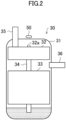
- the compressor (30) is a hermetic scroll compressor.
- the type of compressor (30) is not limited to the scroll type.
- the compressor (30) includes a casing (31), a compression mechanism (32), an electric motor (33), and a drive shaft (34).
- the casing (31) is a standing cylindrical member.
- the compression mechanism (32) is a scroll fluid machine that sucks and compresses the refrigerant.
- the compression mechanism (32) discharges the compressed refrigerant to the internal space of the casing (31) through a discharge port (32a).
- the electric motor (33) is coupled to the compression mechanism (32) through the drive shaft (34) to drive the compression mechanism (32).
- the casing (31) is provided with a suction pipe (35) and a discharge pipe (36). Through the suction pipe (35), the low-pressure refrigerant is introduced into the compression mechanism (32). Through the discharge pipe (36), the high-pressure refrigerant discharged from the compression mechanism (32) is discharged to the outside of the casing (31).
- Refrigerating machine oil is stored on the bottom in the casing (31) of the compressor (30). This refrigerating machine oil is supplied to the compression mechanism (32) through an oil passage (not illustrated) formed in the drive shaft (34), and lubricates the compression mechanism (32). Part of the refrigerating machine oil supplied to the compression mechanism (32) is discharged from the compression mechanism (32) together with the compressed refrigerant. Thus, the gas refrigerant flowing out of the casing (31) through the discharge pipe (36) contains the refrigerating machine oil in the form of mist.
- the refrigerant compressed in the compression mechanism (32) is discharged into the internal space of the casing (31) through the discharge port (32a).
- the refrigerant discharged from the compression mechanism (32) into the internal space of the casing (31) is guided downward of the electric motor (33), then flows upward, and flows out of the casing (31) through the discharge pipe (36).
- the oil separator (40) is a member for separating the refrigerating machine oil from the gas refrigerant discharged from the compressor (30).
- the oil separator (40) is formed in a standing cylindrical shape.
- the discharge pipe (36) of the compressor (30) is connected to the side of the oil separator (40).
- the first port of the four-way switching valve (21) is connected to the top of the oil separator (40).
- One end of the oil return pipe (45) is connected to the bottom of the oil separator (40).
- the refrigerating machine oil is separated from the gas refrigerant having flowed in from the compressor (30).
- the refrigerating machine oil separated from the gas refrigerant falls by the force of gravity, and stays on the bottom in the oil separator (40).
- the oil return pipe (45) is a pipe connecting the oil separator (40) and the suction pipe (35) of the compressor (30) to each other.
- One end of the oil return pipe (45) is connected to the bottom of the oil separator (40), and communicates with the internal space of the oil separator (40).
- the other end of the oil return pipe (45) is connected to the suction pipe (35) of the compressor (30).
- the oil return pipe (45) is provided with the capillary tube (47) and the oil return valve (46).
- the capillary tube (47) and the oil return valve (46) are arranged in this order from one end to the other end of the oil return pipe (45).
- the oil return valve (46) is an electromagnetic valve switchable between an open state and a closed state.
- the discharge temperature sensor (50) is a sensor for measuring the temperature of the refrigerant discharged from the compression mechanism (32) of the compressor (30).
- the discharge temperature sensor (50) is attached to the outer surface of the casing (31) of the compressor (30).
- the discharge temperature sensor (50) is attached to a portion of the top of the casing (31) facing the discharge port (32a) of the compression mechanism (32) (see FIG. 2 ).
- the measured value by the discharge temperature sensor (50) is substantially the temperature of the refrigerant discharged from the compression mechanism (32) before passing by the electric motor (33).
- the discharge temperature sensor (50) may be disposed in the internal space of the casing (31). In this case, the discharge temperature sensor (50) directly contacts the refrigerant discharged from the compression mechanism (32), and measures the temperature of the refrigerant.
- Each of the indoor units (12) includes an indoor heat exchanger (23) and an indoor expansion valve (25).
- the indoor heat exchanger (23) and the indoor expansion valve (25) are arranged in this order from the gas-side end to the liquid-side end of the indoor unit (12).
- each indoor unit (12) includes an indoor fan.
- the indoor heat exchanger (23) is a heat exchanger that allows heat exchange between the refrigerant and indoor air.
- the indoor expansion valve (25) is an electric expansion valve.
- the controller (60) includes a single outdoor controller (61) and a plurality of indoor controllers (64).
- the outdoor controller (61) is provided for the outdoor unit (11).
- One indoor controller (64) is provided for each indoor unit (12).
- the outdoor controller (61) and each indoor controller (64) communicate with each other via wires.
- the outdoor controller (61) includes a microcomputer (62) mounted on a control board, and a memory device (63) storing software for operating the microcomputer (62).
- the memory device (63) is a semiconductor memory.
- the outdoor controller (61) receives measured values from various sensors provided for the outdoor unit (11).
- the outdoor controller (61) controls components provided for the outdoor unit (11).
- the outdoor controller (61) of this embodiment controls the oil return valve (46) based on the measured value by the discharge temperature sensor (50).
- the indoor controller (64) includes a microcomputer and a memory device, as in the outdoor controller (61).
- the indoor controller (64) receives measured values from various sensors provided for the indoor unit (12).
- the indoor controller (64) controls components provided for the indoor unit (12).
- the air conditioner performs a cooling operation and a heating operation.
- the four-way switching valve (21) is set to the first state, and the refrigeration cycle is performed in the refrigerant circuit (15).
- the outdoor heat exchanger (22) functions as a condenser
- the indoor heat exchanger (23) functions as an evaporator.
- the indoor unit (12) blows air cooled in the indoor heat exchanger (23) into an indoor space.
- the four-way switching valve (21) is set to the second state, and the refrigeration cycle is performed in the refrigerant circuit (15).
- the indoor heat exchanger (23) functions as a condenser
- the outdoor heat exchanger (22) functions as an evaporator.
- the indoor unit (12) blows air heated in the indoor heat exchanger (23) into the indoor space.
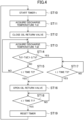
- the outdoor controller (61) performs an operation shown in a flowchart of FIG. 4 as an operation of controlling the oil return valve (46).
- the outdoor controller (61) repeats the operation shown in the flowchart of FIG. 4 at predetermined time intervals T1 (15 minutes in this embodiment).
- Step ST10 in FIG. 4 the outdoor controller (61) starts counting up by a timer.
- the outdoor controller (61) acquires the measured value by the discharge temperature sensor (50), and stores the acquired measured value as a discharge temperature Td1 in the memory device (63).
- the discharge temperature Td1 is the measured value by the discharge temperature sensor (50) before closing of the oil return valve (46) (in other words, in a state of the oil return valve (46) being open).
- Step ST12 the outdoor controller (61) closes the oil return valves (46).
- the outdoor controller (61) acquires the measured value by the discharge temperature sensor (50), and stores the acquired measured value as a discharge temperature Td2 in the memory device (63).
- the discharge temperature Td2 is the measured value by the discharge temperature sensor (50) after closing of the oil return valve (46).
- the outdoor controller (61) determines whether or not a first condition is satisfied.
- the first condition is a condition that a difference (Td1 - Td2) between the discharge temperature Td1 and the discharge temperature Td2 exceeds a predetermined value ⁇ Td (Td1 - Td2 > ⁇ Td).
- the predetermined value ⁇ Td is, for example, 2°C. If the first condition is satisfied, the outdoor controller (61) performs the processing of Step ST17. If the first condition is not satisfied, the outdoor controller (61) performs the processing of Step ST15.
- the outdoor controller (61) determines whether or not the measured time t by the timer has reached a predetermined time T2. If the measured time t is less than the time T2 (t ⁇ T2), the outdoor controller (61) performs the processing of Step ST13. If the measured time t is the time T2 or more (t >_ T2), the outdoor controller (61) performs the processing of Step ST16.
- the time T2 is, for example, 10 seconds.
- a series of processing from Step ST10 to Step ST15 is a detection operation performed by the outdoor controller (61).
- This detection operation is an operation of decreasing the opening degree of the oil return valve (46) and detecting whether or not the gas refrigerant is flowing through the oil return pipe (45) based on a change in the measured value by the discharge temperature sensor (50) after decreasing of the opening degree of the oil return valve (46) as compared to the measured value by the discharge temperature sensor (50) before decreasing of the opening degree of the oil return valve (46).
- the temperature difference (Td1 - Td2) does not reach ⁇ Td even after a lapse of the time T2 since the oil return valve (46) has been closed.
- Td1 - Td2 the temperature difference
- the outdoor controller (61) opens the oil return valve (46).
- the oil return valve (46) is open, the refrigerating machine oil stayed in the oil separator (40) flows into the compressor (30) through the oil return pipe (45).
- Step ST14 if the first condition is satisfied in the processing of Step ST14, it can be determined that mainly the gas refrigerant is flowing through the oil return pipe (45). In this state, part of the refrigerant having flowed out through the discharge pipe (36) of the compressor (30) flows into the suction pipe (35) of the compressor (30) through the oil return pipe (45). Thus, the flow rate of the refrigerant sent from the compressor unit (20) to the four-way switching valve (21) is lower than the flow rate of the refrigerant flowing out through the discharge pipe (36) of the compressor (30).
- Step ST17 the outdoor controller (61) stands by until the measured time t by the timer reaches a predetermined time T3. As a result, the oil return valve (46) is kept closed until the measured time t reaches the time T3.
- the time T3 is, for example, 8 minutes.
- the outdoor controller (61) When the measured time t reaches the time T3 in the processing of Step ST17, the outdoor controller (61) performs the processing of Step ST16. When the measured time t reaches the time T3, the outdoor controller (61) temporarily opens the oil return valve (46) to determine again whether or not the gas refrigerant is flowing through the oil return pipe (45).
- Step ST18 the outdoor controller (61) stands by until the measured time t by the timer reaches the predetermined time T1.
- the time T1 is, for example, 15 minutes.
- the outdoor controller (61) performs the processing of Step ST19.
- Step ST19 the outdoor controller (61) resets the measured time t by the timer. Thereafter, the outdoor controller (61) performs the processing of Step ST10 again.
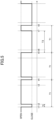
- the outdoor controller (61) starts the detection operation.
- the outdoor controller (61) performs the processing of Step ST12, thereby closing the oil return valve (46).
- the first condition is not satisfied in the processing of Step ST14.
- the outdoor controller (61) performs the processing of Step ST16, thereby opening the oil return valve (46).
- the time t2 is a time when the time T2 has substantially elapsed from the time t1.
- the outdoor controller (61) performs the processing of Step ST18, whereby the oil return valve (46) is kept open until a time t4.
- the time t4 is a time when the time T1 has substantially elapsed from the time 11.
- the outdoor controller (61) starts the next detection operation.
- the outdoor controller (61) starts the detection operation.
- the outdoor controller (61) performs the processing of Step ST12, thereby closing the oil return valve (46).
- the first condition is satisfied in the processing of Step ST14.
- the outdoor controller performs the processing of Step ST17, whereby the oil return valve (46) is kept closed until a time t7.
- the time t7 is a time when the time T3 has substantially elapsed from the time t5.
- the outdoor controller (61) performs the processing of Step ST16, thereby opening the oil return valve (46).
- the outdoor controller (61) performs the processing of Step ST18, whereby the oil return valve (46) is kept open until a time t8.
- the time t8 is a time when the time T1 has substantially elapsed from the time t5.
- the outdoor controller (61) starts the next detection operation.
- the outdoor controller (61) of the controller (60) performs a recovery operation when a predetermined recovery condition is satisfied.
- the recovery operation is an operation of returning the refrigerating machine oil staying outside the compressor unit (20) to the compressor unit (20).
- the recovery condition is, for example, a condition that the cumulative operation time of the air conditioner (10) reaches a predetermined value (e.g., two hours).
- the outdoor controller (61) performs an operation of temporarily maximizing the rotational speed of the compressor (30) as the recovery operation.
- the outdoor controller (61) performs the recovery operation, the flow velocity of the refrigerant flowing through the refrigerant circuit (15) increases, and the refrigerating machine oil staying outside the compressor unit (20) is washed away by the refrigerant and returns to the compressor unit (20) together with the refrigerant.
- the outdoor controller (61) may be configured to perform, as the recovery operation, an operation of increasing the opening degree of the indoor expansion valve (25) during the cooling operation or an operation of increasing the opening degree of the outdoor expansion valve (24) during the heating operation.
- the opening degree of the indoor expansion valve (25) is increased during the cooling operation
- the opening degree of the outdoor expansion valve (24) is increased during the heating operation
- the refrigerant sucked into the compressor (30) is in a wet state.
- the refrigerating machine oil staying outside the compressor unit (20) returns to the compressor unit (20) in a state of being dissolved in the liquid refrigerant.
- the outdoor controller (61) of the controller (60) determines that the gas refrigerant is flowing through the oil return pipe (45) in the detection operation in a case where the rotational speed of the compressor (30) is a predetermined value (e.g., 80% of the maximum rotational speed) or more, the outdoor controller (61) performs the recovery operation even if the recovery condition is not satisfied.
- a predetermined value e.g., 80% of the maximum rotational speed
- the outdoor controller (61) performs the recovery operation of returning the refrigerating machine oil staying outside the compressor unit (20) to the compressor unit (20) regardless of whether or not the recovery condition is satisfied in order to quickly increase the amount of refrigerating machine oil stored in the compressor (30).
- the outdoor controller (61) of the controller (60) does not determine that the gas refrigerant is flowing through the oil return pipe (45) in the detection operation in a case where the rotational speed of the compressor (30) is a predetermined value (e.g., 30% of the maximum rotational speed) or less, the outdoor controller (61) does not perform the recovery operation even if the recovery condition is satisfied. That is, in this case, the recovery operation of the outdoor controller (61) is inhibited.
- a predetermined value e.g. 30% of the maximum rotational speed
- a process from a point A to a point B indicates a compression phase of the compressor (30) in a case where the oil return valve (46) is closed.
- the compression mechanism (32) of the compressor (30) sucks and compresses the refrigerant in the state of the point A, and discharges the refrigerant compressed into the state of the point B.
- the oil return valve (46) is open and mainly the gas refrigerant flows through the oil return pipe (45).
- the gas refrigerant in the state of the point B which has flowed from the oil separator (40) into the oil return pipe (45), is adiabatically expanded into the state of the point C when passing through the capillary tube (47).
- the refrigerant in the state of the point C is sucked into the compression mechanism (32) together with the refrigerant in the state of the point A.
- the refrigerant mixture of the refrigerant in the state of the point A and the refrigerant in the state of the point C is in the state of a point D.
- the compression mechanism (32) sucks and compresses the refrigerant in the state of the point D.
- the refrigerant in the state of the point D is compressed into the state of a point E in the compression mechanism (32).
- the compression phase of the compressor (30) is a process from the point D to the point E (indicated by a broken line).
- the outdoor controller (61) starts the detection operation to close the oil return valve (46) in a state in which mainly the gas refrigerant is flowing through the oil return pipe (45).
- the compression phase of the compressor (30) changes from the process from the point D to the point E to the process from the point A to the point B.
- the state of the refrigerant discharged from the compressor (30) changes from the state of the point E to the state of the point B.
- the temperature of the refrigerant in the state of the point B is lower than the temperature of the refrigerant in the state of the point E.
- the outdoor controller (61) of this embodiment determines that the gas refrigerant is flowing through the oil return pipe (45) when the first condition that "the measured value Td2 of the discharge temperature sensor (50) after the oil return valve (46) has been closed is smaller than the measured value Td1 of the discharge temperature sensor (50) before the oil return valve (46) is closed by the predetermined value ( ⁇ Td) or more" is satisfied.
- the outdoor controller (61) of the controller (60) performs the detection operation.
- the outdoor controller (61) decreases the opening degree of the oil return valve (46), and detects whether or not the gas refrigerant is flowing through the oil return pipe (45) based on the change in the measured value by the discharge temperature sensor (50) after the decreasing of the opening degree of the oil return valve (46) as compared to the measured value by the discharge temperature sensor (50) before the decreasing of the opening degree of the oil return valve (46).
- the outdoor controller (61) detects whether or not the gas refrigerant is flowing through the oil return pipe (45) based on the relative change in the measured value by the discharge temperature sensor (50) before and after the change in the opening degree of the oil return valve (46).
- the cause of the change in the measured value by the discharge temperature sensor (50) in the detection operation of the outdoor controller (61) is substantially only the "change in the opening degree of the oil return valve (46)."
- the outdoor controller (61) performs the detection operation, thereby accurately detecting whether or not the gas refrigerant is flowing through the oil return pipe (45).
- the outdoor controller (61) of the controller (60) determines, in the detection operation, that the gas refrigerant is flowing through the oil return pipe (45)
- the outdoor controller (61) keeps the oil return valve (46) closed for the predetermined time.
- the oil return valve (46) is in the closed state, all the refrigerant discharged from the compressor (30) flows out of the compressor unit (20) to the four-way switching valve (21).
- the flow rate of the refrigerant having flowed out of the compressor unit (20) and circulating in the refrigerant circuit (15) can be kept high, and the air conditioning capacity of the air conditioner (10) can be kept high.
- the outdoor controller (61) of the controller (60) determines that the gas refrigerant is flowing through the oil return pipe (45) in the detection operation in a case where the rotational speed of the compressor (30) is relatively high, the outdoor controller (61) performs the recovery operation even if the recovery condition is not satisfied. This makes it possible to quickly increase the amount of refrigerating machine oil stored in the compressor (30) and prevent damage to the compressor (30) due to poor lubrication.
- the outdoor controller (61) of the controller (60) when the outdoor controller (61) of the controller (60) does not determine that the gas refrigerant is flowing through the oil return pipe (45) in the detection operation in a case where the rotational speed of the compressor (30) is relatively low, the outdoor controller (61) does not perform the recovery operation even if the recovery condition is satisfied. This makes it possible to prevent unnecessary execution of the recovery operation in advance.
- An air conditioner (10) of this embodiment is a modified version of the air conditioner (10) of the first embodiment, in which the controller (60) is changed.
- the controller (60) of this embodiment is different from the controller (60) of the first embodiment in the control of the oil return valve (46) performed by the outdoor controller (61).
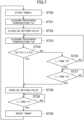
- the control of the oil return valve (46) performed by the outdoor controller (61) of this embodiment will be described with reference to a flowchart of FIG. 7 .
- the outdoor controller (61) repeats the operation shown in the flowchart of FIG. 7 at predetermined time intervals T1 (15 minutes in this embodiment).
- Step ST20 to Step ST23 in the flowchart of FIG. 7 is the same as the processing from Step ST10 to Step ST13 in the flowchart of FIG. 4 .
- the processing in Steps ST28, ST29 in the flowchart of FIG. 7 is the same as the processing in Steps ST18, ST19 in the flowchart of FIG. 4 .
- the processing from Step ST24 to Step ST27 will be described.
- the outdoor controller (61) determines whether or not a second condition is satisfied.
- the second condition is a condition that a difference (Td2 - Td1) between the discharge temperature Td2 and the discharge temperature Td1 exceeds the predetermined value ⁇ Td (Td2 - Td1 > ⁇ Td).
- the predetermined value ⁇ Td is, for example, 2°C. If the second condition is satisfied, the outdoor controller (61) performs the processing of Step ST26. If the second condition is not satisfied, the outdoor controller (61) performs the processing of Step ST25.
- Step ST24 If the second condition is satisfied in the processing of Step ST24, it can be determined that no gas refrigerant is flowing through the oil return pipe (45) (in other words, only the refrigerating machine oil substantially is flowing through the oil return pipe (45)).
- the outdoor controller (61) opens the oil return valve (46).
- the oil return valve (46) is open, the refrigerating machine oil stayed in the oil separator (40) flows into the compressor (30) through the oil return pipe (45).
- the outdoor controller (61) determines whether or not the measured time t of the timer has reached the predetermined time T2. If the measured time t is less than the time T2 (t ⁇ T2), the outdoor controller (61) performs the processing of Step ST23. If the measured time t is the time T2 or more (t > T2), the outdoor controller (61) performs the processing of Step ST27.
- the time T2 is, for example, 10 seconds.
- the temperature difference (Td2 - Td1) does not reach ⁇ Td even after a lapse of the time T2 since the oil return valve (46) was closed. Thus, it can be determined that the gas refrigerant is flowing through the oil return pipe (45).
- Step ST27 the outdoor controller (61) stands by until the measured time t of the timer reaches the predetermined time T3. As a result, the oil return valve (46) is kept closed until the measured time t reaches the time T3.
- the time T3 is, for example, 8 minutes.
- the outdoor controller (61) When the measured time t reaches the time T3 in the processing of Step ST27, the outdoor controller (61) performs the processing of Step ST26. When the measured time t reaches the time T3, the outdoor controller (61) temporarily opens the oil return valve (46) to determine again whether or not the gas refrigerant is flowing through the oil return pipe (45).
- a process from a point A to a point B indicates the compression phase of the compressor (30) when the oil return valve (46) is closed.
- the compression mechanism (32) sucks and compresses the refrigerant in the state of the point A, and discharges the refrigerant compressed into the state of the point B.
- the oil return valve (46) is open and mainly the refrigerating machine oil flows through the oil return pipe (45).
- the temperature of the refrigerating machine oil flowing from the oil separator (40) into the oil return pipe (45) is substantially equal to the temperature of the refrigerant discharged from the compressor (30) (i.e., the refrigerant in the state of the point B).
- the refrigerating machine oil is not adiabatically expanded when passing through the capillary tube (47). Thus, the temperature of the refrigerating machine oil does not decrease while the refrigerating machine oil is passing through the capillary tube (47).
- the refrigerant When the high-temperature refrigerating machine oil having passed through the oil return pipe (45) joins the refrigerant in the state of the point A, the refrigerant is brought into the state of a point F.
- the compression mechanism (32) sucks and compresses the refrigerant in the state of the point F.
- the refrigerant in the state of the point F is compressed into the state of a point G in the compression mechanism (32).
- the compression phase of the compression mechanism (32) the refrigerating machine oil does not receive the compression work. For this reason, part of heat held by the compressed refrigerant is consumed to increase the temperature of the refrigerating machine oil.
- the refrigerant in the state of the point G has a lower specific enthalpy than that of the refrigerant in the state of the point B.
- the compression phase of the compressor (30) is a process from the point F to the point G (indicated by a broken line).
- the outdoor controller (61) starts the detection operation to close the oil return valve (46) in a state in which mainly the refrigerating machine oil is flowing through the oil return pipe (45).
- the compression phase of the compressor (30) changes from the process from the point F to the point G to the process from the point A to the point B.
- the state of the refrigerant discharged from the compression mechanism (32) changes from the state of the point G to the state of the point B.
- the temperature of the refrigerant in the state of the point B is higher than the temperature of the refrigerant in the state of the point G.
- the outdoor controller (61) of this embodiment determines that the gas refrigerant is flowing through the oil return pipe (45) in a case where the second condition that "the measured value Td2 by the discharge temperature sensor (50) after the oil return valve (46) has been closed is greater than the measured value Td1 by the discharge temperature sensor (50) before the oil return valve (46) is closed by the predetermined value ( ⁇ Td) or more" is not satisfied.
- a third embodiment will be described. Thus, the following description will be focused on differences between an air conditioner (10) of this embodiment and the air conditioner (10) of the first embodiment.
- the air conditioner (10) of this embodiment includes two outdoor units (11a, 11b).
- the two outdoor units (11a, 11b) are connected in parallel to each other.
- Each of the outdoor units (11a, 11b) has the same configuration as that of the outdoor unit (11) of the first embodiment.
- Each outdoor unit (11a, 11b) includes a single compressor unit (20a, 20b).
- the first outdoor unit (11a) includes the first compressor unit (20a), and the second outdoor unit (11b) includes the second compressor unit (20b).
- each of the compressor units (20a, 20b) includes a compressor (30a, 30b), an oil separator (40a, 40b), an oil return pipe (45a, 45b), and a discharge temperature sensor (50a, 50b)
- the oil return pipe (45a, 45b) of each compressor unit (20a, 20b) is provided with a capillary tube (47a, 47b) and an oil return valve (46a, 46b).
- Each outdoor unit (11a, 11b) includes a single outdoor controller (61a, 61b).
- the controller (60) of this embodiment includes the outdoor controllers (61a, 61b) of the outdoor units (11a, 11b) and the indoor controllers (64) of the indoor units (12).
- Each of the outdoor controllers (61a, 61b) performs the operation shown in the flowchart of FIG. 4 for the corresponding compressor unit (20a, 20b).
- the outdoor controller (61a) performs the operation shown in the flowchart of FIG. 4 for the first compressor unit (20a).
- the outdoor controller (61a) performs the detection operation using the measured value by the discharge temperature sensor (50a).
- the outdoor controller (61b) performs the operation shown in the flowchart of FIG. 4 for the second compressor unit (20b).
- the outdoor controller (61b) performs the detection operation using the measured value by the discharge temperature sensor (50b).
- the controller (60) of this embodiment performs a transfer operation.
- the transfer operation is an operation of transferring the refrigerating machine oil from the compressor unit (20a, 20b) in which the storage amount of the refrigerating machine oil is relatively great to the compressor unit (20a, 20b) in which the storage amount of the refrigerating machine oil is relatively small.
- the controller (60) performs a transfer operation of transferring the refrigerating machine oil from the first compressor unit (20a) to the second compressor unit (20b).
- the controller (60) performs a transfer operation of transferring the refrigerating machine oil from the second compressor unit (20b) to the first compressor unit (20a).
- the transfer operation of the controller (60) will be described by taking, as an example, a case where the storage amount of the refrigerating machine oil of the first compressor unit (20a) is relatively great and the storage amount of the refrigerating machine oil of the second compressor unit (20b) is relatively small.
- the outdoor controller (61b) of the second outdoor unit (11b) performs the detection operation based on the measured value by the discharge temperature sensor (50b), and determines that mainly the gas refrigerant is flowing through the oil return pipe (45b) of the second compressor unit (20b). Then, the outdoor controller (61b) outputs an oil shortage signal.
- the outdoor controller (61a) by the first outdoor unit (11a) performs the detection operation based on the measured value by the discharge temperature sensor (50a), and determines that no gas refrigerant is flowing through the oil return pipe (45a) of the first compressor unit (20a).
- the outdoor controller (61a) performs the transfer operation when receiving the oil shortage signal output from the outdoor controller (61b) of the second outdoor unit (11b).
- the outdoor controller (61a) of the first outdoor unit (11a) increases the rotational speed of the compressor (30a) of the first compressor unit (20a) by a predetermined value. Moreover, in the transfer operation, the outdoor controller (61a) sends, to the outdoor controller (61b) of the second outdoor unit (11b), a command signal for decreasing the rotational speed of the compressor (30b) of the second compressor unit (20b). The outdoor controller (61b) having received the command signal decreases the rotational speed of the compressor (30b) of the second compressor unit (20b) by the predetermined value.
- the rotational speed of the compressor (30a) of the first compressor unit (20a) increases, whereas the rotational speed of the compressor (30b) of the second compressor unit (20b) decreases.
- the flow rate of the refrigerant circulating in the refrigerant circuit (15) during execution of the transfer operation is equal to the flow rate of the refrigerant circulating in the refrigerant circuit (15) before the start of the transfer operation.
- the air conditioning capacity exhibited by the air conditioner (10) during execution of the transfer operation is kept equal to the air conditioning capacity exhibited by the air conditioner (10) before the start of the transfer operation.
- the controller (60) performs the transfer operation, and this makes it possible to transfer the refrigerating machine oil from the compressor unit (20a, 20b) in which the storage amount of the refrigerating machine oil is relatively great to the compressor unit (20a, 20b) in which the storage amount of the refrigerating machine oil is relatively small. This makes it possible to equalize the storage amount of the refrigerating machine oil in all the compressor units (20a, 20b) and to ensure the reliability of the compressor (30a, 30b) of each of the compressor units (20a, 20b).
- the oil return valve (46) may be an electric valve with a variable opening degree.
- the air conditioner (10) of this variation will be described by taking, as an example, a case where this variation is applied to the air conditioner (10) of the first embodiment.
- the outdoor controller (61) provided for the air conditioner (10) of this variation may change the opening degree of the oil return valve (46) from the maximum opening degree (fully opened) to the minimum opening degree (fully closed) or may decrease the opening degree of the oil return valve (46) from a first opening degree to a second opening degree in the processing of Step ST12 in FIG. 4 .
- the first opening degree and the second opening degree satisfy a relationship of (the minimum opening degree ⁇ the second opening degree ⁇ the first opening degree ⁇ the maximum opening degree).
- the outdoor controller (61) may increase the opening degree of the oil return valve (46) from the second opening degree to a third opening degree in the processing of Step ST16 in FIG. 4 .
- the third opening degree is greater than the first opening degree.
- the first opening degree and the third opening degree satisfy a relationship of (the first opening degree ⁇ the third opening degree ⁇ the maximum opening degree).
- the outdoor controller (61) may perform the processing of Step ST17 after having decreased the opening degree of the oil return valve (46) from the second opening degree to a fourth opening degree when the first condition is satisfied in Step ST14 of FIG. 4 .
- the second opening degree and the fourth opening degree satisfy a relationship of (the minimum opening degree ⁇ the fourth opening degree ⁇ the second opening degree).
- the present disclosure is useful for an air conditioner.
Landscapes
- Engineering & Computer Science (AREA)
- Physics & Mathematics (AREA)
- Mechanical Engineering (AREA)
- Thermal Sciences (AREA)
- General Engineering & Computer Science (AREA)
- Chemical & Material Sciences (AREA)
- Analytical Chemistry (AREA)
- Power Engineering (AREA)
- Air Conditioning Control Device (AREA)
Applications Claiming Priority (2)
| Application Number | Priority Date | Filing Date | Title |
|---|---|---|---|
| JP2022059480A JP7299540B1 (ja) | 2022-03-31 | 2022-03-31 | 冷凍装置 |
| PCT/JP2023/011069 WO2023189874A1 (fr) | 2022-03-31 | 2023-03-22 | Appareil de congélation |
Publications (3)
| Publication Number | Publication Date |
|---|---|
| EP4491969A1 true EP4491969A1 (fr) | 2025-01-15 |
| EP4491969A4 EP4491969A4 (fr) | 2025-05-21 |
| EP4491969B1 EP4491969B1 (fr) | 2026-01-14 |
Family
ID=86900699
Family Applications (1)
| Application Number | Title | Priority Date | Filing Date |
|---|---|---|---|
| EP23779888.9A Active EP4491969B1 (fr) | 2022-03-31 | 2023-03-22 | Appareil de congélation |
Country Status (5)
| Country | Link |
|---|---|
| US (1) | US20250020374A1 (fr) |
| EP (1) | EP4491969B1 (fr) |
| JP (1) | JP7299540B1 (fr) |
| CN (1) | CN118922675B (fr) |
| WO (1) | WO2023189874A1 (fr) |
Families Citing this family (1)
| Publication number | Priority date | Publication date | Assignee | Title |
|---|---|---|---|---|
| WO2025141717A1 (fr) * | 2023-12-26 | 2025-07-03 | 三菱電機株式会社 | Dispositif à cycle de réfrigération |
Family Cites Families (13)
| Publication number | Priority date | Publication date | Assignee | Title |
|---|---|---|---|---|
| JP2006207917A (ja) * | 2005-01-27 | 2006-08-10 | Mitsubishi Heavy Ind Ltd | 空気調和装置およびその運転方法 |
| JP2006214602A (ja) * | 2005-02-01 | 2006-08-17 | Matsushita Electric Ind Co Ltd | 冷凍サイクル装置 |
| JP4996645B2 (ja) * | 2009-03-31 | 2012-08-08 | サンデン株式会社 | 冷却システム |
| JP5414482B2 (ja) * | 2009-12-01 | 2014-02-12 | 日立アプライアンス株式会社 | 空気調和機 |
| JP5418253B2 (ja) * | 2010-01-28 | 2014-02-19 | パナソニック株式会社 | 冷凍サイクル装置 |
| JP2013204821A (ja) * | 2012-03-27 | 2013-10-07 | Fujitsu General Ltd | 空気調和機 |
| JP6286844B2 (ja) * | 2013-03-21 | 2018-03-07 | アイシン精機株式会社 | 空調装置 |
| CN103743157B (zh) * | 2014-01-09 | 2016-08-31 | 广东美的制冷设备有限公司 | 压缩机系统、空调器和压缩机的回油控制方法 |
| GB2552432B (en) * | 2015-03-27 | 2020-08-05 | Mitsubishi Electric Corp | Refrigeration cycle apparatus |
| JP6390688B2 (ja) * | 2016-11-24 | 2018-09-19 | ダイキン工業株式会社 | 冷凍装置 |
| JP2019078440A (ja) * | 2017-10-24 | 2019-05-23 | パナソニックIpマネジメント株式会社 | 空気調和機 |
| CN109357439A (zh) * | 2018-10-17 | 2019-02-19 | 宁波奥克斯电气股份有限公司 | 一种压缩机排气温度的控制方法及空调器 |
| CN113939700A (zh) * | 2019-05-31 | 2022-01-14 | 大金工业株式会社 | 制冷装置 |
-
2022
- 2022-03-31 JP JP2022059480A patent/JP7299540B1/ja active Active
-
2023
- 2023-03-22 WO PCT/JP2023/011069 patent/WO2023189874A1/fr not_active Ceased
- 2023-03-22 EP EP23779888.9A patent/EP4491969B1/fr active Active
- 2023-03-22 CN CN202380029418.2A patent/CN118922675B/zh active Active
-
2024
- 2024-09-30 US US18/901,301 patent/US20250020374A1/en active Pending
Also Published As
| Publication number | Publication date |
|---|---|
| JP7299540B1 (ja) | 2023-06-28 |
| JP2023150385A (ja) | 2023-10-16 |
| EP4491969B1 (fr) | 2026-01-14 |
| EP4491969A4 (fr) | 2025-05-21 |
| CN118922675A (zh) | 2024-11-08 |
| US20250020374A1 (en) | 2025-01-16 |
| WO2023189874A1 (fr) | 2023-10-05 |
| CN118922675B (zh) | 2025-03-07 |
Similar Documents
| Publication | Publication Date | Title |
|---|---|---|
| EP2320159A1 (fr) | Dispositif de réfrigération | |
| EP1942306B1 (fr) | Appareil de climatisation, procédé de remplissage de réfrigerant dans un appareil de climatisation et procédé de nettoyage de remplissage/conduite de réfrigerant pour climatiseur | |
| EP3279580B1 (fr) | Dispositif de climatisation | |
| EP2196746B1 (fr) | Appareil de réfrigération | |
| EP2402681B1 (fr) | Unité de réfrigération | |
| EP3859247B1 (fr) | Dispositif de climatisation | |
| EP2511630B1 (fr) | Climatiseur et procédé de détection de la quantité de fluide frigorigène pour le climatiseur | |
| EP2068101A1 (fr) | Climatiseur | |
| EP2012075A1 (fr) | Dispositif de réfrigération | |
| EP3358276B1 (fr) | Système de climatisation | |
| EP3059521A1 (fr) | Dispositif de climatisation | |
| EP2256435A1 (fr) | Climatiseur multi-type et son procédé d'opération de retour d'huile | |
| US11874039B2 (en) | Refrigeration cycle apparatus | |
| EP4343215B1 (fr) | Dispositif à cycle frigorifique | |
| EP4491969A1 (fr) | Appareil de congélation | |
| EP3101372B1 (fr) | Unité de congélation | |
| EP3967950A1 (fr) | Dispositif de réfrigération | |
| KR100614364B1 (ko) | 냉동 장치 | |
| CN108954501B (zh) | 空调机 | |
| EP4166873B1 (fr) | Dispositif à cycle de réfrigération | |
| JPWO2017094172A1 (ja) | 空気調和装置 | |
| JP2005037052A (ja) | 空気調和機 | |
| KR20080089962A (ko) | 공기조화기 | |
| EP4286768B1 (fr) | Dispositif à cycle frigorifique | |
| EP3486578A1 (fr) | Dispositif de réfrigération |
Legal Events
| Date | Code | Title | Description |
|---|---|---|---|
| STAA | Information on the status of an ep patent application or granted ep patent |
Free format text: STATUS: THE INTERNATIONAL PUBLICATION HAS BEEN MADE |
|
| PUAI | Public reference made under article 153(3) epc to a published international application that has entered the european phase |
Free format text: ORIGINAL CODE: 0009012 |
|
| STAA | Information on the status of an ep patent application or granted ep patent |
Free format text: STATUS: REQUEST FOR EXAMINATION WAS MADE |
|
| 17P | Request for examination filed |
Effective date: 20241010 |
|
| AK | Designated contracting states |
Kind code of ref document: A1 Designated state(s): AL AT BE BG CH CY CZ DE DK EE ES FI FR GB GR HR HU IE IS IT LI LT LU LV MC ME MK MT NL NO PL PT RO RS SE SI SK SM TR |
|
| A4 | Supplementary search report drawn up and despatched |
Effective date: 20250422 |
|
| RIC1 | Information provided on ipc code assigned before grant |
Ipc: F25B 13/00 20060101ALI20250414BHEP Ipc: F25B 31/00 20060101ALI20250414BHEP Ipc: F25B 49/02 20060101ALI20250414BHEP Ipc: F24F 11/89 20180101ALI20250414BHEP Ipc: F25B 1/00 20060101AFI20250414BHEP |
|
| DAV | Request for validation of the european patent (deleted) | ||
| DAX | Request for extension of the european patent (deleted) | ||
| GRAP | Despatch of communication of intention to grant a patent |
Free format text: ORIGINAL CODE: EPIDOSNIGR1 |
|
| STAA | Information on the status of an ep patent application or granted ep patent |
Free format text: STATUS: GRANT OF PATENT IS INTENDED |
|
| P01 | Opt-out of the competence of the unified patent court (upc) registered |
Free format text: CASE NUMBER: UPC_APP_3799_4491969/2025 Effective date: 20250820 |
|
| INTG | Intention to grant announced |
Effective date: 20250916 |
|
| GRAS | Grant fee paid |
Free format text: ORIGINAL CODE: EPIDOSNIGR3 |
|
| GRAA | (expected) grant |
Free format text: ORIGINAL CODE: 0009210 |
|
| STAA | Information on the status of an ep patent application or granted ep patent |
Free format text: STATUS: THE PATENT HAS BEEN GRANTED |
|
| AK | Designated contracting states |
Kind code of ref document: B1 Designated state(s): AL AT BE BG CH CY CZ DE DK EE ES FI FR GB GR HR HU IE IS IT LI LT LU LV MC ME MK MT NL NO PL PT RO RS SE SI SK SM TR |
|
| REG | Reference to a national code |
Ref country code: CH Ref legal event code: F10 Free format text: ST27 STATUS EVENT CODE: U-0-0-F10-F00 (AS PROVIDED BY THE NATIONAL OFFICE) Effective date: 20260114 Ref country code: GB Ref legal event code: FG4D |
|
| REG | Reference to a national code |
Ref country code: DE Ref legal event code: R096 Ref document number: 602023010820 Country of ref document: DE |
|
| REG | Reference to a national code |
Ref country code: IE Ref legal event code: FG4D |
|
| PGFP | Annual fee paid to national office [announced via postgrant information from national office to epo] |
Ref country code: DE Payment date: 20260319 Year of fee payment: 4 |
|
| PGFP | Annual fee paid to national office [announced via postgrant information from national office to epo] |
Ref country code: AT Payment date: 20260301 Year of fee payment: 4 |
|
| PGFP | Annual fee paid to national office [announced via postgrant information from national office to epo] |
Ref country code: FR Payment date: 20260323 Year of fee payment: 4 |