EP4491996A1 - Vorrichtung zum messen eines laserbandes - Google Patents
Vorrichtung zum messen eines laserbandes Download PDFInfo
- Publication number
- EP4491996A1 EP4491996A1 EP24181765.9A EP24181765A EP4491996A1 EP 4491996 A1 EP4491996 A1 EP 4491996A1 EP 24181765 A EP24181765 A EP 24181765A EP 4491996 A1 EP4491996 A1 EP 4491996A1
- Authority
- EP
- European Patent Office
- Prior art keywords
- housing
- tapeline
- laser
- casing
- cavity
- Prior art date
- Legal status (The legal status is an assumption and is not a legal conclusion. Google has not performed a legal analysis and makes no representation as to the accuracy of the status listed.)
- Pending
Links
Images
Classifications
-
- G—PHYSICS
- G01—MEASURING; TESTING
- G01B—MEASURING LENGTH, THICKNESS OR SIMILAR LINEAR DIMENSIONS; MEASURING ANGLES; MEASURING AREAS; MEASURING IRREGULARITIES OF SURFACES OR CONTOURS
- G01B3/00—Measuring instruments characterised by the use of mechanical techniques
- G01B3/10—Measuring tapes
- G01B3/1041—Measuring tapes characterised by casings
-
- G—PHYSICS
- G01—MEASURING; TESTING
- G01S—RADIO DIRECTION-FINDING; RADIO NAVIGATION; DETERMINING DISTANCE OR VELOCITY BY USE OF RADIO WAVES; LOCATING OR PRESENCE-DETECTING BY USE OF THE REFLECTION OR RERADIATION OF RADIO WAVES; ANALOGOUS ARRANGEMENTS USING OTHER WAVES
- G01S7/00—Details of systems according to groups G01S13/00, G01S15/00, G01S17/00
- G01S7/48—Details of systems according to groups G01S13/00, G01S15/00, G01S17/00 of systems according to group G01S17/00
- G01S7/51—Display arrangements
-
- G—PHYSICS
- G01—MEASURING; TESTING
- G01B—MEASURING LENGTH, THICKNESS OR SIMILAR LINEAR DIMENSIONS; MEASURING ANGLES; MEASURING AREAS; MEASURING IRREGULARITIES OF SURFACES OR CONTOURS
- G01B3/00—Measuring instruments characterised by the use of mechanical techniques
- G01B3/10—Measuring tapes
- G01B3/1005—Means for controlling winding or unwinding of tapes
-
- G—PHYSICS
- G01—MEASURING; TESTING
- G01B—MEASURING LENGTH, THICKNESS OR SIMILAR LINEAR DIMENSIONS; MEASURING ANGLES; MEASURING AREAS; MEASURING IRREGULARITIES OF SURFACES OR CONTOURS
- G01B3/00—Measuring instruments characterised by the use of mechanical techniques
- G01B3/10—Measuring tapes
- G01B3/1084—Tapes combined with arrangements for functions other than measuring lengths
- G01B3/1092—Tapes combined with arrangements for functions other than measuring lengths for performing length measurements and at least one other measurement of a different nature, e.g. bubble-type level
-
- G—PHYSICS
- G01—MEASURING; TESTING
- G01S—RADIO DIRECTION-FINDING; RADIO NAVIGATION; DETERMINING DISTANCE OR VELOCITY BY USE OF RADIO WAVES; LOCATING OR PRESENCE-DETECTING BY USE OF THE REFLECTION OR RERADIATION OF RADIO WAVES; ANALOGOUS ARRANGEMENTS USING OTHER WAVES
- G01S17/00—Systems using the reflection or reradiation of electromagnetic waves other than radio waves, e.g. lidar systems
- G01S17/02—Systems using the reflection of electromagnetic waves other than radio waves
- G01S17/06—Systems determining position data of a target
- G01S17/08—Systems determining position data of a target for measuring distance only
-
- G—PHYSICS
- G01—MEASURING; TESTING
- G01B—MEASURING LENGTH, THICKNESS OR SIMILAR LINEAR DIMENSIONS; MEASURING ANGLES; MEASURING AREAS; MEASURING IRREGULARITIES OF SURFACES OR CONTOURS
- G01B11/00—Measuring arrangements characterised by the use of optical techniques
- G01B11/02—Measuring arrangements characterised by the use of optical techniques for measuring length, width or thickness
- G01B11/026—Measuring arrangements characterised by the use of optical techniques for measuring length, width or thickness by measuring distance between sensor and object
-
- G—PHYSICS
- G01—MEASURING; TESTING
- G01B—MEASURING LENGTH, THICKNESS OR SIMILAR LINEAR DIMENSIONS; MEASURING ANGLES; MEASURING AREAS; MEASURING IRREGULARITIES OF SURFACES OR CONTOURS
- G01B3/00—Measuring instruments characterised by the use of mechanical techniques
- G01B3/10—Measuring tapes
- G01B3/1005—Means for controlling winding or unwinding of tapes
- G01B2003/1023—Winding mechanisms
-
- G—PHYSICS
- G01—MEASURING; TESTING
- G01B—MEASURING LENGTH, THICKNESS OR SIMILAR LINEAR DIMENSIONS; MEASURING ANGLES; MEASURING AREAS; MEASURING IRREGULARITIES OF SURFACES OR CONTOURS
- G01B3/00—Measuring instruments characterised by the use of mechanical techniques
- G01B3/10—Measuring tapes
- G01B3/1041—Measuring tapes characterised by casings
- G01B3/1043—Details of internal structure thereof, e.g. means for coupling separately moulded casing halves
Definitions
- Tapelines and laser ranging devices are common distance measuring tools. They have found applications in the fields of building construction, interior decoration, traffic accident disposition, and the like.
- the tape end part and the measuring terminal end of the tape need to be respectively level with the starting end and the terminal end of the object to be measured.
- the person making the measurement needs to use his/her hands or other auxiliary equipment to keep the tape on the object to be measured.
- an ordinary tapeline is inconvenient to operate and has lower measurement accuracy. For example, in the field of measurement at hazardous locations, the practicality of the ordinary tapeline is relatively poor.
- the ordinary tapeline usually has a measurement range of 5 meters, 7. 5 meters or 10 meters.
- Some specially made tapelines may have a measurement range of up to 15 meters or 20 meters.
- the larger the measurement range of the tapeline the larger the volume of the tapeline.
- the laser ranging device of the prior art has higher measurement accuracy than a tapeline, it also has a larger volume and higher cost, and is inconvenient to carry and use. After being used over a long period, the light-emitting surface of the laser light source and the light-receiving surface of the light-sensitive device will experience relatively large abrasion, thereby affecting light ray feedback sensitivity and distance measuring accuracy. Moreover, the laser ranging device has larger errors in short-distance measurements, which greatly limits its use in some fields such as interior decoration. Further, it difficult to use in large-scale applications.
- US Patent No. 11,143,494 discloses a distance measuring device that combines a tapeline measurement device and a laser measuring device in a single case.
- the case is comprised of a first housing and a second housing with a third housing arranged between the first housing and the second housing, The third housing and the second housing together from a tapeline cavity where the edges of the third housing surround part of the cavity and extend into the second housing completely around the cavity.
- a measuring tape is provided inside the tapeline cavity.
- the third housing of US Patent No. 11,143,494 is difficult to manufacture because of its side walls that completely surround the tapeline cavity and extend into the second housing. Also, being one piece, it makes assembly of the device complicated. In particular, both the tapeline wheel and the laser ranging devices, which sit in the first and second housing, have to be completely assembled before the third housing can be installed between the other two housing and all three are fastened together.
- a laser tape measurement device has both a tape measure in at tapeline cavity and a laser measuring device in an adjacent cavity.
- it is somewhat like that described in US Patent No. 11,143,494 .
- it does not have a third housing with end walls that surround all of the tapeline cavity and also form part of an enclosure for the laser measuring device.
- the third housing of the prior art is required to have side walls that are perpendicular to a vertical wall or bottom face. These side walls are received within the second housing in order to completely surround the tapeline cavity in conjunction with the second housing
- the laser tape measurement device of the present invention has left and right housings or shells.
- the interior of the device is divided into a laser ranging device on one side and a tapeline structure located in a cavity on the other side.
- a tapeline wheel with measuring tape wrapped about it is located in the tapeline cavity.
- a lower plate covers approximately the bottom third of the tapeline cavity. It has a side wall that extend only into and is fasten to the lower part of the right housing.
- There is an upper plate which has no end walls extending to the right housing. Instead, it has a flat surface facing the tapeline cavity and covering two-thirds of its height. The other side of the upper housing is fastened to the left housing which contains the laser ranging device.
- the present invention uses lower and upper housings instead of a single third housing. These housings are much similar in design than the prior third housing and thus are easier to mold. Further, because they attach to the tapeline and laser ranging portions respectively, the device is earlier to assemble.
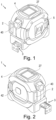
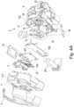
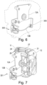
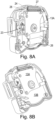
- the laser tape measuring device of the present invention has an external casing 1 that includes a first shell or housing 11 and a second shell or housing 12.
- the device includes a laser ranging device 2 and a tapeline structure 3, a sheath 4 and a clip 5.
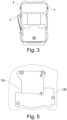
- Clip 5 is used to clip the distance measuring device on the waistband of the user, which is convenient to carry the device.
- the device includes a viewing panel 27 through which the measurements from the laser ranging device can be viewed. The viewing panel is parallel to the bottom surface of the casing, i.e., it is horizonal and not as some angle.
- there is a tape retraction bottom 40 on the front that allows an extended tape to be withdrawn into the casing and a laser on/off switch on the left side of the device.
- the first housing 11 includes a first housing bottom face 111 ( FIG. 4B ) and a first housing side wall 112.
- the second housing 12 includes a second housing bottom face 121 and a second housing side wall 122.
- the second housing side wall 122 is connected to the first housing side wall 112, together forming the side wall and bottom face of the casing 1.
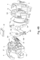
- upper interior plate 13A and a lower interior plate 13B that divide the interior into the laser ranging device 2 and the tapeline structure 3 as shown in FIGS. 4A & 4B .
- the tapeline structure there is a cavity 14 in which a tapeline wheel 31 is located.
- upper interior plate 13A has small side walls 301 along its top that project to the left toward the laser ranging device 2. Otherwise it has no significant side walls.
- the lower interior plate 13B has side walls primarily at the front 303 and back 305 that project toward the tapeline structure. See FIGS. 4B & 6 . See FIG. 7 .
- the upper interior plate 13A covers part of the tapeline cavity 14, it does not wrap around or enclose it because of the lack of side walls extending from it into cavity 14.
- the lower interior plate 13B has only partial side walls at the front, back that extend into cavity 14. However, they do so only so as to enclose the bottom third of tape wheel 31.
- the device of the present invention may further include a sheath 4 which can be made of elastic material or soft material, partially or fully covering the first housing side wall 112 and the second housing side wall 122, and/or partially or fully covering the joint between the first housing bottom face 111 and the first housing side wall 112.
- the sheath 4 serves to enhance the feel of the device in the hand of the user, increasing the friction coefficient between the device and the user's hand, which helps to prevent the device from sliding out of the user's hand. Further, if the device slides out of the user's hand, the sheath has a certain cushioning effect, and increases the potential protection of the internal electronic devices and mechanical structures from breakage.
- the tapeline structure 3 includes tapeline wheel 31, a tape 32 (shown in dotted line in FIG. 4A ), a tape outlet 33 and a press block 34.
- the tapeline wheel 31 is rotatably mounted in the tapeline cavity 14 and the tape 32 is fully or partially wound onto the tapeline wheel 31, i.e., one end of the tape 32 is fixed to the tapeline wheel 31.
- a spring device (not shown) is mounted on the wheel and seeks to wind up the tape completely on the wheel so it is in an original position.
- the other end to the tape extends pass the press block 34 and through outlet 33 to a tapeline end portion 36.
- the press block forms a locking mechanism for locking a length of the tape extending out of the casing 1 through the tape outlet 33. A user can overcome the spring force of the wheel and the press block to withdraw the tape from the device while making a measurement.
- the press block 34 presses against the tape 32 due to an attached spring force, such that the length of the tape 32 outside the casing 1 is held constant against being drawn back into the casing by the spring force on the wheel 31 seeking to wind up the tape. While the tape remains stationary due to the press block it can be read by the user.
- the tape retraction button 40 is pressed, the press block is lifted from the tape and it is wound back onto the wheel to restore it to its original position.
- the laser ranging device 2 includes a laser beam generator, a photodetector, a circuit board 23 with a processor, a display means 24 and a power supply in the form of batteries 26.
- the laser beam generator and the photodetector can be arranged side by side, or one above the other, and they are integrally combined. In one embodiment the laser generator and photodetector are arranged next to each other and are both recessed in the first housing side wall 112.
- the processor on circuit board 23 is connected to the laser generator and the photodetector, which acquires the feedback electrical signal.
- the processor uses the feedback signal from the photodetector to calculate the distance from an object to be measured to the distance measuring device.
- the processor issues a control signal to command the laser beam generator to emit laser beams toward the object to be measured.
- the measurement light beams are reflected from the surface of the object to be measured and generate reflective light rays. At least the reflected light rays parallel with the measurement light beams are captured by the photodetector and are converted into the electrical feedback signal that is provided to the processer.
- the processor has a timer to record a time point when the laser generator emits laser beams due to the user operating button 42 and a time point when the feedback electric signal is obtained. Based on the time difference between the two time points, the distance from the object to be measured to the distance measuring device can be calculated. During this period of time, the laser beam goes back and forth between the object to be measured and the distance measuring device at the light velocity. Half of the product of the time difference and the light velocity is the distance to be measured between the object to he measured and the distance measuring device.
- the measuring device of the present invention further includes a display 24, a viewing panel 27 and a display mounting bracket 28.
- the viewing panel 27 is made of transparent material and arranged at the surface of the first housing 11 and/or the second housing 12, for protecting the display 24.
- the display mounting bracket 28 inwardly protrudes from the first housing bottom face 111 and the first housing side wall 112 and is arranged opposite to and parallel with the viewing panel 27.
- the display 24 is preferably a display screen connected to the processor for displaying the distance from the object to the distance measuring device.
Landscapes
- Physics & Mathematics (AREA)
- General Physics & Mathematics (AREA)
- Engineering & Computer Science (AREA)
- Electromagnetism (AREA)
- Computer Networks & Wireless Communication (AREA)
- Radar, Positioning & Navigation (AREA)
- Remote Sensing (AREA)
- Optical Radar Systems And Details Thereof (AREA)
Applications Claiming Priority (1)
| Application Number | Priority Date | Filing Date | Title |
|---|---|---|---|
| US18/340,801 US20240426993A1 (en) | 2023-06-23 | 2023-06-23 | Laser tape measure device |
Publications (1)
| Publication Number | Publication Date |
|---|---|
| EP4491996A1 true EP4491996A1 (de) | 2025-01-15 |
Family
ID=91530345
Family Applications (1)
| Application Number | Title | Priority Date | Filing Date |
|---|---|---|---|
| EP24181765.9A Pending EP4491996A1 (de) | 2023-06-23 | 2024-06-12 | Vorrichtung zum messen eines laserbandes |
Country Status (3)
| Country | Link |
|---|---|
| US (1) | US20240426993A1 (de) |
| EP (1) | EP4491996A1 (de) |
| CA (1) | CA3242067A1 (de) |
Citations (6)
| Publication number | Priority date | Publication date | Assignee | Title |
|---|---|---|---|---|
| CN207020310U (zh) * | 2017-06-21 | 2018-02-16 | 杭州巨星科技股份有限公司 | 一种测距装置 |
| CN208269762U (zh) * | 2018-05-18 | 2018-12-21 | 宁波长城精工实业有限公司 | 附带激光测距功能的卷尺 |
| AU2016427468A1 (en) * | 2016-10-25 | 2019-05-16 | Hangzhou Great Star Industrial Co., Ltd. | Distance measuring device |
| CN209371910U (zh) * | 2018-11-15 | 2019-09-10 | 北京顺科达科技有限公司 | 一种激光卷尺 |
| US11143404B2 (en) | 2016-03-30 | 2021-10-12 | Mitsubishi Power, Ltd. | Combustor and gas turbine |
| US11143494B2 (en) | 2017-06-21 | 2021-10-12 | Hangzhou Great Star Industrial Co., Ltd. | Distance measuring device |
Family Cites Families (22)
| Publication number | Priority date | Publication date | Assignee | Title |
|---|---|---|---|---|
| US5182863A (en) * | 1990-10-22 | 1993-02-02 | Spectra-Physics Laserplane, Inc. | Automatic plumb and level tool with acoustic measuring capability |
| US6612046B1 (en) * | 2001-06-11 | 2003-09-02 | Nci Engineering Technologies, Ltd | Marking device |
| US6868620B2 (en) * | 2002-08-01 | 2005-03-22 | Solar Wide Industrial, Ltd. | Digital measuring instrument having flexible measuring line |
| US20040221470A1 (en) * | 2003-05-09 | 2004-11-11 | Index Measuring Tape Co., Ltd. | Tape rule having laser indicating mechanism |
| US20040237326A1 (en) * | 2003-05-27 | 2004-12-02 | Chien-Kuo Wang | Multifunctional measuring tape assembly |
| US7024791B2 (en) * | 2004-01-12 | 2006-04-11 | Black & Decker Inc. | Tape measure with laser beam |
| US7377050B2 (en) * | 2006-04-03 | 2008-05-27 | Irwin Industrial Tool Company | Tape measure |
| KR20080103494A (ko) * | 2008-11-05 | 2008-11-27 | 조성빈 | 다기능 줄자 |
| US8356419B2 (en) * | 2009-04-29 | 2013-01-22 | Peter Maxwell Lord | Digital measuring device |
| US8407909B2 (en) * | 2010-09-03 | 2013-04-02 | James Scullion Lindsay | Tape measure carrier and gauge |
| US8863399B2 (en) * | 2011-08-26 | 2014-10-21 | Milwaukee Electric Tool Corporation | Tape measure |
| TWM447982U (zh) * | 2012-09-28 | 2013-03-01 | Precaster Entpr Co Ltd | 雙系統量測裝置 |
| CN105627857B (zh) * | 2014-11-04 | 2018-08-07 | 南京德朔实业有限公司 | 卷尺 |
| US10563968B2 (en) * | 2016-12-09 | 2020-02-18 | Richard Mrozinski | Tape measure and recorder device |
| CN114485309B (zh) * | 2017-03-24 | 2024-08-02 | 米沃奇电动工具公司 | 具有基于流体的收回速度控制器的卷尺 |
| US10634476B1 (en) * | 2017-04-21 | 2020-04-28 | Bautista Innovations, Llc | Measuring tool |
| US11402192B2 (en) * | 2018-07-12 | 2022-08-02 | Apex Brands, Inc. | Measuring tape with improved case durability |
| CN208443280U (zh) * | 2018-07-26 | 2019-01-29 | 启东市石力机电有限公司 | 一种模块化的激光卷尺 |
| WO2020160598A1 (en) * | 2019-02-06 | 2020-08-13 | Whitehead Peter Edward | Laser distance measurement apparatus |
| CN218120787U (zh) * | 2022-06-29 | 2022-12-23 | 杭州巨星科技股份有限公司 | 卷尺 |
| US11906296B1 (en) * | 2023-02-27 | 2024-02-20 | Mileseey Technology (US) Inc. | Distance measuring device and method |
| CN116294882A (zh) * | 2023-02-27 | 2023-06-23 | 深圳市迈测科技股份有限公司 | 测距装置 |
-
2023
- 2023-06-23 US US18/340,801 patent/US20240426993A1/en active Pending
-
2024
- 2024-06-12 EP EP24181765.9A patent/EP4491996A1/de active Pending
- 2024-06-19 CA CA3242067A patent/CA3242067A1/en active Pending
Patent Citations (6)
| Publication number | Priority date | Publication date | Assignee | Title |
|---|---|---|---|---|
| US11143404B2 (en) | 2016-03-30 | 2021-10-12 | Mitsubishi Power, Ltd. | Combustor and gas turbine |
| AU2016427468A1 (en) * | 2016-10-25 | 2019-05-16 | Hangzhou Great Star Industrial Co., Ltd. | Distance measuring device |
| CN207020310U (zh) * | 2017-06-21 | 2018-02-16 | 杭州巨星科技股份有限公司 | 一种测距装置 |
| US11143494B2 (en) | 2017-06-21 | 2021-10-12 | Hangzhou Great Star Industrial Co., Ltd. | Distance measuring device |
| CN208269762U (zh) * | 2018-05-18 | 2018-12-21 | 宁波长城精工实业有限公司 | 附带激光测距功能的卷尺 |
| CN209371910U (zh) * | 2018-11-15 | 2019-09-10 | 北京顺科达科技有限公司 | 一种激光卷尺 |
Also Published As
| Publication number | Publication date |
|---|---|
| CA3242067A1 (en) | 2025-10-30 |
| US20240426993A1 (en) | 2024-12-26 |
Similar Documents
| Publication | Publication Date | Title |
|---|---|---|
| EP3998497B1 (de) | Abstandsmesser | |
| JP2021144059A (ja) | 距離測定装置 | |
| CN206274346U (zh) | 一种测距装置 | |
| US12392900B2 (en) | Distance measuring device | |
| CN109633673B (zh) | 传感器模块 | |
| CN207020310U (zh) | 一种测距装置 | |
| EP4491996A1 (de) | Vorrichtung zum messen eines laserbandes | |
| CN208269762U (zh) | 附带激光测距功能的卷尺 | |
| HK40120301A (en) | Laser tape measure device | |
| CN107976682A (zh) | 一种测距装置 | |
| CN116294882A (zh) | 测距装置 | |
| JP7197081B2 (ja) | 距離測定装置 | |
| CN119881921A (zh) | 一种测距装置 | |
| CN208443280U (zh) | 一种模块化的激光卷尺 | |
| CN217820826U (zh) | 一种防水激光测距仪 | |
| CN220064364U (zh) | 一种测距装置 | |
| US20040221470A1 (en) | Tape rule having laser indicating mechanism | |
| CA3041368C (en) | Distance measuring device | |
| CN207423118U (zh) | 一种手持式激光测高仪 | |
| CN215326352U (zh) | 一种手持非接触测量梯级与裙板间隙的装置 | |
| CN218380877U (zh) | 一种用于盾构机盾尾间隙的单线激光测量系统和装置 | |
| CN213301225U (zh) | 一种房产测绘用手持测绘仪 | |
| CN212253878U (zh) | 一种激光卷尺 | |
| CN210513429U (zh) | 一种红外侦拍仪结构 | |
| CN209783743U (zh) | 一种可投影的红外测温仪 |
Legal Events
| Date | Code | Title | Description |
|---|---|---|---|
| PUAI | Public reference made under article 153(3) epc to a published international application that has entered the european phase |
Free format text: ORIGINAL CODE: 0009012 |
|
| STAA | Information on the status of an ep patent application or granted ep patent |
Free format text: STATUS: THE APPLICATION HAS BEEN PUBLISHED |
|
| AK | Designated contracting states |
Kind code of ref document: A1 Designated state(s): AL AT BE BG CH CY CZ DE DK EE ES FI FR GB GR HR HU IE IS IT LI LT LU LV MC ME MK MT NL NO PL PT RO RS SE SI SK SM TR |
|
| STAA | Information on the status of an ep patent application or granted ep patent |
Free format text: STATUS: REQUEST FOR EXAMINATION WAS MADE |
|
| 17P | Request for examination filed |
Effective date: 20250701 |
|
| REG | Reference to a national code |
Ref country code: HK Ref legal event code: DE Ref document number: 40120301 Country of ref document: HK |
|
| GRAP | Despatch of communication of intention to grant a patent |
Free format text: ORIGINAL CODE: EPIDOSNIGR1 |
|
| STAA | Information on the status of an ep patent application or granted ep patent |
Free format text: STATUS: GRANT OF PATENT IS INTENDED |
|
| INTG | Intention to grant announced |
Effective date: 20251103 |
|
| GRAJ | Information related to disapproval of communication of intention to grant by the applicant or resumption of examination proceedings by the epo deleted |
Free format text: ORIGINAL CODE: EPIDOSDIGR1 |
|
| STAA | Information on the status of an ep patent application or granted ep patent |
Free format text: STATUS: REQUEST FOR EXAMINATION WAS MADE |
|
| GRAS | Grant fee paid |
Free format text: ORIGINAL CODE: EPIDOSNIGR3 |
|
| STAA | Information on the status of an ep patent application or granted ep patent |
Free format text: STATUS: GRANT OF PATENT IS INTENDED |
|
| GRAJ | Information related to disapproval of communication of intention to grant by the applicant or resumption of examination proceedings by the epo deleted |
Free format text: ORIGINAL CODE: EPIDOSDIGR1 |
|
| GRAP | Despatch of communication of intention to grant a patent |
Free format text: ORIGINAL CODE: EPIDOSNIGR1 |
|
| STAA | Information on the status of an ep patent application or granted ep patent |
Free format text: STATUS: REQUEST FOR EXAMINATION WAS MADE |
|
| INTC | Intention to grant announced (deleted) | ||
| GRAP | Despatch of communication of intention to grant a patent |
Free format text: ORIGINAL CODE: EPIDOSNIGR1 |
|
| STAA | Information on the status of an ep patent application or granted ep patent |
Free format text: STATUS: GRANT OF PATENT IS INTENDED |