EP4492018A1 - Interféromètres opto-acoustiques sur puce - Google Patents
Interféromètres opto-acoustiques sur puce Download PDFInfo
- Publication number
- EP4492018A1 EP4492018A1 EP23184785.6A EP23184785A EP4492018A1 EP 4492018 A1 EP4492018 A1 EP 4492018A1 EP 23184785 A EP23184785 A EP 23184785A EP 4492018 A1 EP4492018 A1 EP 4492018A1
- Authority
- EP
- European Patent Office
- Prior art keywords
- membrane
- waveguide
- primary
- auxiliary
- transducer element
- Prior art date
- Legal status (The legal status is an assumption and is not a legal conclusion. Google has not performed a legal analysis and makes no representation as to the accuracy of the status listed.)
- Withdrawn
Links
Images


Classifications
-
- G—PHYSICS
- G01—MEASURING; TESTING
- G01H—MEASUREMENT OF MECHANICAL VIBRATIONS OR ULTRASONIC, SONIC OR INFRASONIC WAVES
- G01H9/00—Measuring mechanical vibrations or ultrasonic, sonic or infrasonic waves by using radiation-sensitive means, e.g. optical means
- G01H9/004—Measuring mechanical vibrations or ultrasonic, sonic or infrasonic waves by using radiation-sensitive means, e.g. optical means using fibre optic sensors
-
- A—HUMAN NECESSITIES
- A61—MEDICAL OR VETERINARY SCIENCE; HYGIENE
- A61B—DIAGNOSIS; SURGERY; IDENTIFICATION
- A61B5/00—Measuring for diagnostic purposes; Identification of persons
- A61B5/0093—Detecting, measuring or recording by applying one single type of energy and measuring its conversion into another type of energy
- A61B5/0097—Detecting, measuring or recording by applying one single type of energy and measuring its conversion into another type of energy by applying acoustic waves and detecting light, i.e. acousto-optic measurements
-
- A—HUMAN NECESSITIES
- A61—MEDICAL OR VETERINARY SCIENCE; HYGIENE
- A61B—DIAGNOSIS; SURGERY; IDENTIFICATION
- A61B5/00—Measuring for diagnostic purposes; Identification of persons
- A61B5/68—Arrangements of detecting, measuring or recording means, e.g. sensors, in relation to patient
- A61B5/6846—Arrangements of detecting, measuring or recording means, e.g. sensors, in relation to patient specially adapted to be brought in contact with an internal body part, i.e. invasive
- A61B5/6847—Arrangements of detecting, measuring or recording means, e.g. sensors, in relation to patient specially adapted to be brought in contact with an internal body part, i.e. invasive mounted on an invasive device
- A61B5/6852—Catheters
-
- G—PHYSICS
- G02—OPTICS
- G02B—OPTICAL ELEMENTS, SYSTEMS OR APPARATUS
- G02B6/00—Light guides; Structural details of arrangements comprising light guides and other optical elements, e.g. couplings
- G02B6/10—Light guides; Structural details of arrangements comprising light guides and other optical elements, e.g. couplings of the optical waveguide type
- G02B6/12—Light guides; Structural details of arrangements comprising light guides and other optical elements, e.g. couplings of the optical waveguide type of the integrated circuit kind
- G02B6/122—Basic optical elements, e.g. light-guiding paths
- G02B6/125—Bends, branchings or intersections
Definitions
- the present disclosure relates to an on-chip opto-acoustic transducer element for converting an acoustic pressure wave into a modulation of a property of light.
- the present disclosure further relates to an ultrasound receiver, an imager assembly comprising said transducer element and to a method of manufacturing.
- the basic principle is that one or more acoustic source sends out an ultrasound signal into a sample, e.g. tissue.
- Ultrasound receivers are used to detect an output signal in the form of amplitude and/or phase.
- Tomography allows the construction of a three-dimensional image of the tissue.
- multiple emitters and/or receivers are used, and advanced signal optimization and processing to optimize results.
- Opto-acoustic receivers comprising a resonator supporting an optical wave guide for converting an acoustic pressure wave into a modulation of a property of light are known.
- the mechanical resonance frequency of the receiver is typically matched to the frequency of the ultrasound signal, so that mechanical amplification of the modulation can be obtained.
- optical waveguide loops which fit on a particular membrane. Even if it does fit, for small membranes the optical waveguides are not necessarily located on optimal sites on the membrane.
- the minimal bend radius of the optical wave guides also limits the minimal membrane diameter and therefore upper resonance frequency.
- WO2021145766A1 discloses a photonic device having a sensing waveguide that extends across a plurality of membranes.
- WO2021145766A1 relates to a photonic integrated device that comprises a substrate, a plurality of mechanical resonator structures on a surface of the substrate, exposed to receive sound waves from outside the device; a plurality of sensing optical waveguides, each sensing optical waveguide at least partly mechanically coupled to at least one of the mechanical resonator structures, or a sensing optical waveguide that is at least partly mechanically coupled to all of the mechanical resonator structures.
- US2020319019A1 discloses a ring resonator comprising an optical waveguide that extends over a plurality of membranes.
- aspects of the present disclosure relate to an on-chip integrated opto-acoustic transducer element; an on-chip ultrasound receiver device comprising the transducer element; and to an ultrasound imager assembly comprising the transducer element as disclosed herein. Further aspects relate to a process of manufacturing an opto-acoustic transducer element, preferably the opto-acoustic transducer element as disclosed herein.
- the opto-acoustic transducer element and/or the receiver can be embodied as an on chip device, e.g. a fully integrated on chip device.
- the presented opto-acoustic transducer element can particularly be used for opto-acoustic imaging with one or more of: improved sensitivity, improved resolution, decreased form factor, and for imaging at comparatively higher acoustic frequencies than known devices with a comparable signal to noise level.
- the on-chip integrated opto-acoustic transducer element comprises at least a carrier substrate having a membrane layer extending over an aperture in a surface of the substrate.
- the aperture may be fully etched through the substrate, or may be a recess.
- the membrane is configured to deflect in response to a received acoustic pressure wave, typically an external acoustic pressure wave.
- the transducer further comprises at least a primary photonic waveguide disposed at the membrane, and an auxiliary photonic waveguide disposed at the membrane, wherein the primary waveguide and the auxiliary photonic waveguide follow a respective primary and auxiliary trajectory which extend over a respective first zone (z1) of the membrane and a respective second zone (z2) of the membrane providing opposite sign expansion/contraction of the waveguide due to a deflection of the membrane in response to the acoustic pressure wave.
- Positioning the primary photonic waveguide and the auxiliary photonic waveguide along zones providing opposite sign expansion/contraction of the waveguide due to a deflection of the membrane can effectively double an output (e.g. a phase difference or light intensity) of the transducer element.
- the waveguide is typically a so-called single mode waveguide. It will be appreciated that the concepts as disclosed herein can be applied to multimode waveguides, unless clear from context or stated to the contrary,
- the opto-acoustic transducer can be used to advantage for converting an acoustic pressure wave into a modulation of a property of light, e.g. for the detection of ultrasound and/or for the construction of an image, e.g. as in ultrasound imaging devices such as medical ultrasound imagers.
- the transducer can be configured to operate according to known sensing principles.
- the primary and auxiliary waveguide can be arranged according to interference based sensing principles (e.g. as in a Mach Zehnder interferometer configuration) or according to optical resonance principles (e.g. as in in a ring resonator).
- the properties of the waveguides can be less restricted by the properties/dimensioning of the membrane (e.g. shape, dimension, resonance properties).
- the present disclosure allows guiding the waveguide along comparatively smaller membranes (higher resonance frequencies) than conventional resonators wherein the waveguide follows a spiraling trajectory at the membrane.
- the waveguides follow a largely (>50%) curved trajectory at the membrane, more preferably the trajectories follow predominately (>75%) curved trajectory where in contact with the membrane, or even a trajectory that is curved over >95% of its length , e.g. up to essentially its entire length (>99% or even 100%), at the membrane.
- the improved S/N can be attributed to a larger total integrated absolute effect (positive or negative) on the light path properties within the waveguide due to deflection of the membrane as compared to waveguides following a straight trajectory.
- the primary and auxiliary curved trajectory each have a radius of curvature larger than a radius of curvature of the membrane, at least where in contact with the membrane. Extending the waveguides across a plurality of membranes can be especially relevant for small membranes (for high frequency imaging) which, due to their small dimension, cannot accommodate long waveguides (e.g. a spiral shaped section).
- the membranes are provided in an array spanning an area having a size equal or smaller than half the wavelength of the acoustic wave squared. If the pitch is larger than 0.5*wavelength, the transducer may not adhere to the spatial sampling criterion, which may impart sensitivity to sound incoming from unwanted directions.
- the first and second zones are at opposing sides of the membrane across a neutral bending plane (N) of the resonator membrane.
- Positioning the primary photonic waveguide and the auxiliary photonic waveguide at opposing sides of the membrane can advantageously provide a configuration wherein light propagating within the waveguides experience an opposite signal response, for each out of plane deflection of the membrane (e.g. a fundamental resonance mode).
- Positioning the primary photonic waveguide and the auxiliary photonic waveguide along opposing sides of the membrane zones can effective provide an up to double interferometric output of the transducer element.
- first zone and the second zone are laterally spaced along the same side of the membrane at positions having an out of phase deflection in accordance with a higher harmonic resonance mode of the membrane.
- positions having an out of phase deflection in accordance with a higher harmonic resonance mode can be determined experimentally for a given membrane (e.g. by optical microscopy and/or modelling).
- having an out of phase deflection e.g.
- n ⁇ ⁇ phase shift, in accordance with a higher harmonic resonance mode can be determined in accordance with a method as disclosed herein and/or by providing anisotropy within the membrane and/or an anisotropy between adjacent membranes. Positioning the primary photonic waveguide and the auxiliary photonic waveguide at positions experiencing an out of phase deflection in accordance with a higher harmonic resonance mode of the membrane can up to double an interferometric output of the transducer element.
- At least one of the primary curved trajectory and auxiliary curved trajectory extend along a plurality of membranes, each membrane having a lateral dimension smaller than a maximum radius of curvature of the primary curved and auxiliary curved trajectory at the membrane.
- the plurality of membranes are organized in an area smaller than half of the wavelength ( ⁇ p) of the acoustic pressure wave squared, i.e. ( ⁇ p/2) 2 .
- the membrane can be provided with an anisotropic pre-stress.
- an anisotropic pre-stress can advantageously realize a preorientation of higher order resonance modes of the membrane (e.g. 2 nd order resonance). Preorientation can advantageously ease a manufacturing of the device as the preorientation can be used as a priori input for the relative and/or absolute position/orientation of the waveguide(s) at the membrane.
- preorientation can be realized by providing (or inducing) a membrane having a crystalline anisotropy.
- preorientation can be realized by providing a coupled membrane array, e.g. an array of membranes with anisotropic spacing between adjacent ones.
- the membrane is comprised in an array of membranes whereby a spacing between adjacent membranes along orthogonal directions within the array differs by an amount providing directional coupling of second or higher order harmonic resonance modes of the membranes.
- the array can be a two dimensional grid (e.g. an mxn grid) whereby the spacing along columns differs from the spacing along rows.
- predictable directionality of membrane resonance modes can be provided by providing a specific shape having anisotropic resonant behavior (e.g. elliptical, rectangular, or other shapes as known in the field).
- one or more of the waveguide can physically, or at least conceptually, be considered to comprise a configuration having a first waveguide portion, a second waveguide portion, and a waveguide coupler.
- the waveguide coupler is disposed between the first and the second waveguide portions and interconnects the portions to provide an extended light path.
- the two waveguide portions can effectively be interpreted as a continuous elongated waveguide.
- the waveguide can be embodied as a sensing arm of interferometric measurement configuration, including but not limited to a so-called Mach-Zender interferometric configuration (MZI) or a Fabry-Perot-interferometer.
- MZI Mach-Zender interferometric configuration
- the waveguide can be embodied as part of a ring resonator measurement configuration.
- the interconnected configuration as disclosed herein advantageously allows for increased sensitivity for a membrane as compared to devices having a conventional waveguide for the same membrane.
- the coupler can be realized as what is also referred to herein as a merged coupler, or a merged interconnect.
- an on-chip opto-acoustic transducer element for converting an acoustic pressure wave into a modulation of a property of light, the transducer element comprising: a membrane extending over an aperture in a surface of the carrier substrate; and a waveguide layer structure disposed at the membrane, the waveguide layer structure comprising a waveguide providing a light path extending between an input and an output, the waveguide comprising: a first waveguide portion; a second waveguide portion, and wherein the first waveguide portion continues into the second waveguide portion under an abrupt angle forming a merged interconnect.
- the interconnect terminates at a mirror element configured to reflect light traveling along one of the first and the second portion section to the other.
- the mirror element can be an upstanding sidewall of the waveguide, whereby the sidewall and waveguide portions are arranged to reflect a propagating wave by total internal reflection.
- the transducer element as disclosed wherein at least one of the primary photonic waveguide and the auxiliary photonic waveguide comprises a first curved waveguide section and a second curved waveguide section that are interconnected by a coupler, wherein the first waveguide section continues into the second waveguide section under an abrupt angle forming a merged interconnect, the interconnect terminating at a mirror element configured to reflect light traveling along one of the first and the second section to the other, forming the coupler.
- this advantageously increase sensitivity.
- the conventional S-shaped coupler can be entirely dispensed with while realizing a comparable or even increased overall length of the waveguide along a given membrane.
- the present disclosure can realize beneficial waveguide routing along the membrane without in plane waveguide crossings.
- the primary photonic waveguide and the auxiliary photonic waveguide are spiral shaped, each having a first spiral section and a second spiral waveguide section that spiral inwardly, respectively outwardly, about a center of the first zone, respectively the second zone.
- the first and the second spiral waveguide section are interconnected by the coupler element. As compared to a spiral comprising a conventional S-Shaped section the interconnected coupler can realize a more dense coverage along the membrane.
- an ultrasound receiver device According to a further aspect there is provided an ultrasound receiver device.
- the opto-acoustic transducer element and/or the opto-acoustic receiver can be embodied as an on-chip device, e.g. a fully integrated on-chip device.
- the receiver comprises: an on-chip opto-acoustic transducer element according to the present disclosure.
- the receiver further includes: at least one light input and one or more light output operably connected to the primary photonic waveguide and the auxiliary photonic waveguide, and readout circuitry including one or more light detector operably connected to the one or more light output and configured to provide as, electrical signals, an output based on a detected light intensity and/or phase shift.
- an ultrasound imager system comprises: the on-chip ultrasound receiver element as disclosed herein; an ultrasound transmitter; a light source operably connected to the one or more on-chip ultrasound receiver element, a processing unit configured for controlling the ultrasound source, photo acoustic receiver, the light source and the readout circuitry, and a signal processor for construction an image using the output of the readout circuitry.
- the method further comprises a step of determining characteristics of the primary and auxiliary trajectory.
- the parameter space can comprise one or more of a length, a radius of curvature, and a relative position of the first and the second trajectory for a given membrane.
- the determining can comprise modelling process, e.g. a finite element modelling, comprising: maximizing a pathlength difference between the primary and auxiliary waveguide by, for both the primary and auxiliary waveguide, integrating local contributions to contraction/expansions over the length of the waveguide due to the deflection of the membrane.
- the method further comprises a step of fixing an orientation of a second or higher order harmonic resonance mode of the membrane by one or more of: providing an anisotropic pre-stress to the membrane; forming the membrane of a layer having a crystalline anisotropy; and/or providing the membrane in an array of membranes whereby a spacing between adjacent membrane along orthogonal directions within the array differs by an amount providing directional coupling.
- the present disclosure in a broad sense relates to ultrasound receivers.
- the disclosure aims to provide an improved sensitivity and/or to enable imaging at comparatively higher acoustic frequencies over known IPUTs.
- the acoustic operating frequency can advantageously be ⁇ 10 MHz e.g. ⁇ 100 MHz.
- a primary application of ultrasound receivers is in medical imaging systems. For example, for imaging of (human) tissue and organs.
- the basic principle involves that an acoustic source sends out an ultrasound signal into the tissue.
- the signal is picked up by a receiver element.
- the receiver includes a transducer for converting an acoustic pressure wave into a modulation of a property of light.
- the amplitude and/or phase of light as detected by an ultrasound receiver can allow the construction of a three-dimensional image.
- Multiple emitters and/or receivers can be used, in combination with advanced signal optimization and processing to optimize results. Operating at higher frequencies can advantageously increase imaging resolution.
- An objective of the present disclosure is to increase the receiver sensitivity per unit area.
- Increasing the sensitivity can advantageously improve a signal-to-noise ratio and therefore a better image quality, which can be particularly relevant in view of medical regulations on the limitation of the emitted acoustic energy of the acoustic emitter.
- increasing sensitivity can advantageously compensate for attenuation of the ultrasound signals, e.g. during propagation through tissue, so that features can be imaged from a comparatively increased distance.
- increased sensitivity can advantageously improve imaging resolution by enabling imaging at comparatively shorter acoustic wavelengths, where the ultrasound attenuation is generally higher.
- a small receiver can, for example, be fitted into catheters for in-vivo imaging.
- the size of the transducer aperture/recess is determined by the acoustic wavelength (spatial sampling). So for an array transducer, the size of the individual elements would become smaller with IPUTs in accordance with the present disclosure, but the pitch can still be the same.
- a mechanical resonance frequency of the receiver is typically matched to the frequency of the ultrasound signal, so that mechanical amplification is obtained. Short acoustic wavelengths for high-resolution imaging thus benefit from small receivers having high mechanical resonance frequencies.
- the present disclosure pertains to opto-acoustic ultrasound receivers.
- a membrane is excited by the ultrasound signal.
- photonic waveguide-based devices provided such as ring resonators or interferometer devices such as Mach Zehnder Interferometers (MZIs).
- MZIs Mach Zehnder Interferometers
- the optical wavelength response of the photonic device is altered as the ultrasound signal deflects the membrane.
- the photonic device transmission is generally observed at one optical wavelength, and the transmitted optical power is representative for the ultrasound signal.
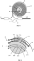
- FIG 1 illustrates an ultra sound receiver concept redrawn from a publication by S.M. Leinders, et al in Nature Scientific Reports, 14328, (2015 ).
- the receiver comprises a carrier substrate 9 and a membrane layer 5.
- the membrane spans across an aperture (or recess) 6 in the substrate.
- the membrane deflects in response to an acoustic pressure wave (P).
- P acoustic pressure wave
- the mechanical resonance frequency of the membrane is matched to the frequency of the ultrasound signal as emitted by emitter 150.
- the device comprises a pair of optical waveguides.
- the waveguides include a primary waveguide 1 embodied as a ring resonator and an auxiliary waveguide 2 including a coupling section 2a.
- the waveguide can be embodied as an interferometer.
- the waveguide structure 4 typically also includes at least a primary waveguide 1 and an auxiliary waveguide 2, whereby the primary waveguide 1 (also referred to as sensing waveguide) extends along the membrane and the auxiliary waveguide 2 (typically not at the membrane) is referred to as a reference waveguide.
- the sensing waveguide 1 can be provided as a double spiral, e.g. as shown in FIG 2A .
- the waveguide makes a 180 degree turn (see e.g. Figure 4A and B ).
- spiral can conceptually be interpreted as including a first waveguide portion 1a and a second waveguide portion 1b that are interconnected at a coupler element 8 and that combinedly provide a light path extending between an input 20 and an output 30.
- the conventional turn (8t) occupies a large area of the membrane due to the minimum bending radius (r min ) of the waveguide, below which optical losses within the waveguide rapidly increase. This large area does not add to sensitivity, and sets a limit to the minimum membrane size and therefore to the maximum mechanical resonance frequency.
- the plurality of the membranes can be organized at the carrier substrate 9 in an area smaller than half of the wavelength ( ⁇ p) of the acoustic pressure wave squared.
- FIGs 2A and 2B provide a top view image and a partial cross-section side view illustrating aspects of an ultrasound imager assembly 200 according to the present disclosure.
- the imager assembly 200 includes a receiver device 100, an on-chip transducer element 10, and one or more of a light source 110, a readout circuitry 40, and a processing unit 120.
- the ultrasound imager assembly 200 can also include one or more ultrasound transmitter 150 (see figure 2B ).
- a plurality of waveguide couplers/splitters 140 are provided to interconnect the respective waveguides.
- the readout circuitry 40 is configured to provide, as electrical signals, an output (S) based on a detected light intensity and/or phase shift.
- the processing unit 120 is configured for processing the output.
- the readout circuitry 40 includes light sensors 41 (only one indicated for clarity) operably connected to the one or more output 30 and configured to provide as, electrical signals, an output (S) based on a detected light intensity and/or phase shift.
- light output 1 and 2 correspond to a phase difference interference between spiraling waveguides 1 and 2.
- Light output 3 (out 3) corresponds to the output of the single loop waveguides 1c and 2c and output 4 (out 4) corresponds to a power tap output and can be used to optimize a power output of light source 110.
- the transducer element comprises at least a membrane 5 extending over an aperture 6 in a surface of a carrier substrate 9 and a waveguide layer structure 4 disposed at the membrane.
- the membrane 5 is configured to have a resonance mode (typically a principal resonance mode) within a frequency range of the emitter for a desired medium to be imaged (e.g. water, tissue).
- the waveguide layer structure 4 comprises at least a primary waveguide 1 providing a light path extending between an input 20 and an output 30.
- auxiliary photonic waveguide 2 is illustrated as being located outside the membrane.
- the primary photonic waveguide and auxiliary photonic waveguide are both disposed along the same membrane or multiple membranes at positions that, during operation, provide opposite sign expansion/contraction of the waveguide due to a deflection of the membrane in response to the acoustic pressure wave.
- the primary and reference waveguide are depicted as conventional spirals having a 180 degree turn at the center. While the primary and/or secondary photonic waveguide may take such configuration in some embodiments, a double spiral is not essential. In fact some preferred embodiments other layouts are preferred. Details as to the positioning and shape of the waveguide trajectories will be explained in further detail with reference to FIGs 3 to 17 .
- a minimal achievable noise equivalent pressure (NEP) of Interferometer IPUTs can be understood as being limited by foundry and material platform limitations regarding optical wave guide geometries (minimal bend radius, optical wave guide losses), which limits the amount of optical waveguide loops that can be fitted on a particular membrane.
- optical wave guide geometries minimal bend radius, optical wave guide losses
- the minimal bend radius of the optical wave guides can limit a minimal membrane diameter and therefore upper resonance frequency.
- a transducer element wherein at least one of the primary curved trajectory and auxiliary curved trajectory extend along a plurality of the membranes, each membrane having a lateral dimension smaller than a radius of curvature of the primary curved and auxiliary curved trajectory at the membrane.
- FIGs 3A, 3B, 3C , 4A, and 5 illustrate exemplary embodiments wherein at least one, preferably both of the primary and secondary photonic waveguide 1,2 extend along a plurality of membranes.
- the membrane can have a radius of curvature that is smaller than a radius of curvature of the waveguide.
- FIGs 3A-3C illustrate embodiments wherein the respective waveguides are routed along a plurality of membranes.
- NEP noise equivalent pressure
- m represents the number of membranes
- e represents the fundamental charge
- B represents the bandwidth
- Tdelay represents the transmission of the waveguide on one membrane
- P0 represents the laser power
- R represents the detector responsivity
- E represents the Young's modulus
- v represents the Posson ratio
- ⁇ represents the wavelength
- n represents the waveguide effective index
- p represents the waveguide heart-to-heart spacing
- z represents the distance of the waveguide centre to the center of the membrane
- h represents the membrane thickness
- Rm represents the membrane radius
- rmin represents the minimum waveguide bend radius.
- the waveguides in embodiments according to the present disclosure are routed over zones of the membrane that impart an opposite overall response.
- one of the primary photonic waveguide 1 and the auxiliary photonic waveguide 2 follows a comparatively more outward curve than the other.
- the zones imparting an opposite overall response can be understood as being positions having an out of phase deflection, e.g. an n times ⁇ phase shift, in accordance with a higher harmonic resonance mode of the membrane.
- FIGs 14 to 17 the principle underlying the improved sensitivity as used in embodiments illustrated in some variations, e.g. as in FIG 3 , is explained in more detail.
- FIG 14A a membrane 5 is shown in which a plurality of trajectories is indicated for curved waveguides WG-n (two of which are marked in the left image (WG-1 and WG-2).
- the WGs all have a radius of curvature greater than a radius of the membrane but with a different offset ⁇ a'.
- FIG 14B illustrates that the relative position of the WGs on the membrane during primary mode resonance affects the overall contribution to overall contributions in the light path.
- FIG 14B illustrates, for a circular membrane, an out of plane deflection during a primary resonance mode. As indicated deflection is largest at the center of the membrane (red) and decreases to zero near the edges of the membrane (indicated by dashed line).
- waveguides (WG-1,WG-2) that curve along opposite sides of the membrane center (c) experience an opposite effect during membrane. Specifically, the waveguide (WG2) following an outer curve experiences an overall expansion as integrated over the length of the waveguide, whereas the more inward waveguide (WG1) experiences more compressive forces. It was found that a difference between length of the waveguides (dL) depends on an offset of the waveguides.
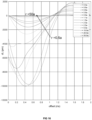
- FIG 16 illustrates how dL (in picometers) of a curved waveguides varies with offset (r/a). Note that the results presented are for a membrane with radius (R 5 ) of 88 ⁇ m, and waveguides with a radius of curvature (R WG ) of 88 ⁇ m, for a n acoustic wave at a pressure of 1e+05 Pa. As indicated dL varies with offset (r/a) with a negative difference at low offsets and a positive dL at larger offsets. Note that for a negative pressure (-1e+05) the inverse behavior is found. As can be seen in Fig 17 a linear relation (on a log-log plot) was found between dL and the radius of the waveguide.
- FIG 6 an embodiment is depicted wherein the first and second zones (z1,z2) are at opposing sides of the same membrane 5 across a neutral bending plane (N).
- FIG 6A and B illustrate a membrane 5 having a primary photonic waveguide 1 disposed on a front side s1 and an auxiliary photonic waveguide 2 on a backside s2 of the same membrane.
- the waveguides can be disposed on a front, respectively a backside of different membranes.
- Figure 6C illustrates an embodiment of a transducer element according to a MZI configuration having one input and three outputs.
- the secondary waveguide (as positioned opposingly to the primary photonic waveguide) can be coupled to the multimode interference couplers (positioned in the same plane as the primary waveguide) by a so called vertical coupler element 8.
- This element vertically couples positions of waveguides that are in respective vertically separated layers.
- the coupler can comprise a section of a first waveguide and a section of the second waveguide portion, whereby the sections co-propagate with respect to each other forming an overlap (as seen in a plan view) thereby optically coupling the waveguides.
- the first zone z1 and the second zone z2 are laterally spaced along the same side of the membrane at positions having an out of phase (e.g. an integer times ⁇ ) deflection in accordance with a higher harmonic resonance mode of the membrane.
- the higher order mode can be a second order resonance mode.
- the zones having opposite sign deflection z1 z2 can be understood as being centered around loci having maximum deflection at the second order resonance.
- the waveguides can follow an appropriate trajectory.
- the waveguide can follow a spiraling trajectory.
- the waveguides can follow a curved trajectory whereby a radius of curvature of the waveguide is larger than a radius of the membrane.
- the last variation can be particularly suitable for embodiments intended to operate with very small membranes (e.g. for operating at high resonance frequencies.
- one or more of the waveguides may be directed a plurality of times across individual membranes.
- Fig 12 illustrates a variation wherein the primary and auxiliary photonic waveguide 1,2 are routed across the membrane multiple times.
- each of the waveguides can be understood as being comprised of a plurality of segments that are interconnected by a coupler 8.
- At least one of the primary photonic waveguide 1 and the auxiliary photonic waveguide 2 comprises a first curved waveguide section 1-1, 2-1 and a second curved waveguide section 1-2, 2-2 that are interconnected by a coupler 8, wherein the first waveguide section continues into the second waveguide section under an abrupt angle forming a merged interconnect, the interconnect terminating at a mirror element configured to reflect light traveling along one of the first and the second section to the other, forming the coupler.
- the mirror element can be an upstanding sidewall of the waveguide, whereby the sidewall and waveguide potions are arranged to reflect a propagating wave by total internal reflection.
- the coupler may be a conventional coupler (e.g. an S-shaped section as shown in Fig 4B .
- the light is redirected by means of a mirror 11.
- Two bent waveguides are terminated at the mirror with a mutual angle. If the condition of total internal reflection is satisfied the reflection can be essentially lossless. In practice, some optical loss can occur, e.g. due to a roughness at mirror or an off-vertical positioning and/or poor definition of the waveguide at the overlap (indicated by dashed lines). Note that the center of gravity of a light wave propagating in a curving waveguides tends to be near to the outer bend as opposed to the inner bend (indicated by the double dot-dashed line).
- the mirror element is an upstanding sidewall 1w of the waveguide.
- the angle ( ⁇ ) is larger than two times a critical angle of incidence for total internal reflection.
- an angle ⁇ between the respective waveguides can be ⁇ than about 60°.
- Very steep angles, e.g. ⁇ 20° can be less preferred because this would increase a dimension of the overlap.
- the mirror element may be a sidewall of the waveguide having reflective coating (e.g. metal).
- both the first waveguide section and the second waveguide section each comprise a spiral portion, such as a spiral represented by an Archimedean spiral, an involute of a circle, or a Fermat's spiral.
- FIG 13 a method of manufacturing an opto-acoustic transducer is described. The method comprises the steps of:
- the method further comprises a step of determining (302) one or more of a physical characteristic of the first and the second trajectory with respect to each other and the membrane prior step 304.
- the characteristic can include one or more of a size, shape, position and orientation of the waveguide with respect to each other and/or with respect to the membrane.
- determining 302 can be realized by prior modelling response characteristics of the primary and auxiliary waveguide, e.g. by a finite element modelling process, comprising: maximizing a pathlength difference (dL) between the primary and auxiliary waveguide.
- the pathlength difference can be suitably optimized by integrating local contributions to contraction/expansions over the length of the waveguide due to the deflection of the membrane
- the method can comprise a step of fixing 303 an orientation of a second or higher order harmonic resonance mode of the membrane.
- Step 303 can comprise one or more of: providing an anisotropic pre-stress to the membrane; forming the membrane of a layer having a crystalline anisotropy; and/or providing the membrane in an array of membranes whereby a spacing between adjacent membranes along orthogonal directions within the array differs by an amount providing directional mode coupling of second or higher order harmonic resonance modes of the membranes.
- FIG 15A and 15B provide details at to a realization of mode coupling by providing an array of membranes with an anisotropic spacing.
- preferential mode coupling can be obtained whereby higher order resonance modes of the membranes line up along a predefined direction, e.g. along the direction indicated by the arrow in FIG 15B .
- Preferential mode coupling can be obtained by providing one or more of a prestress, crystalline anisotropy , or anisotropic spacing.
- a prestress e.g. a prestress
- crystalline anisotropy e.g. a crystalline anisotropy
- anisotropic spacing e.g. a crystalline anisotropy , or anisotropic spacing.
- FIG 15A spacing between adjacent membranes (d1) along a direction differs from a spacing (d2) in a direction orthogonal thereto.
- Absolute and relative values of spacings can be determined using published methods. In general the spacing along different directions d1-d2) is larger than about 0.1 times a radius of the membranes.
Landscapes
- Life Sciences & Earth Sciences (AREA)
- Physics & Mathematics (AREA)
- Health & Medical Sciences (AREA)
- Heart & Thoracic Surgery (AREA)
- Molecular Biology (AREA)
- Pathology (AREA)
- Engineering & Computer Science (AREA)
- Biomedical Technology (AREA)
- Acoustics & Sound (AREA)
- Medical Informatics (AREA)
- Biophysics (AREA)
- Surgery (AREA)
- Animal Behavior & Ethology (AREA)
- General Health & Medical Sciences (AREA)
- Public Health (AREA)
- Veterinary Medicine (AREA)
- General Physics & Mathematics (AREA)
- Optical Integrated Circuits (AREA)
Priority Applications (2)
| Application Number | Priority Date | Filing Date | Title |
|---|---|---|---|
| EP23184785.6A EP4492018A1 (fr) | 2023-07-11 | 2023-07-11 | Interféromètres opto-acoustiques sur puce |
| PCT/NL2024/050378 WO2025014369A1 (fr) | 2023-07-11 | 2024-07-10 | Interféromètres optoacoustiques sur puce |
Applications Claiming Priority (1)
| Application Number | Priority Date | Filing Date | Title |
|---|---|---|---|
| EP23184785.6A EP4492018A1 (fr) | 2023-07-11 | 2023-07-11 | Interféromètres opto-acoustiques sur puce |
Publications (1)
| Publication Number | Publication Date |
|---|---|
| EP4492018A1 true EP4492018A1 (fr) | 2025-01-15 |
Family
ID=87340657
Family Applications (1)
| Application Number | Title | Priority Date | Filing Date |
|---|---|---|---|
| EP23184785.6A Withdrawn EP4492018A1 (fr) | 2023-07-11 | 2023-07-11 | Interféromètres opto-acoustiques sur puce |
Country Status (2)
| Country | Link |
|---|---|
| EP (1) | EP4492018A1 (fr) |
| WO (1) | WO2025014369A1 (fr) |
Citations (6)
| Publication number | Priority date | Publication date | Assignee | Title |
|---|---|---|---|---|
| US20110187868A1 (en) * | 2007-08-27 | 2011-08-04 | Canon Kabushiki Kaisha | Acoustic-wave sensor, acoustic-wave sensor array, and ultrasonic imaging apparatus |
| US20200319019A1 (en) | 2019-04-04 | 2020-10-08 | Imec Vzw | Acoustical pressure sensor with photonic waveguide |
| US20210108978A1 (en) * | 2018-04-16 | 2021-04-15 | Ams International Ag | Photonic device, method for operating a photonic device and method for manufacturing a photonic device |
| EP3851815A1 (fr) | 2020-01-16 | 2021-07-21 | Nederlandse Organisatie voor toegepast- natuurwetenschappelijk Onderzoek TNO | Dispositif photonique intégré pour convertir le son en une modulation d'une propriété de la lumière |
| WO2021145766A1 (fr) | 2020-01-16 | 2021-07-22 | Nederlandse Organisatie Voor Toegepast- Natuurwetenschappelijk Onderzoek Tno | Dispositif photonique intégré pour convertir un son en une modulation de propriétés de lumière dans le dispositif |
| US11408764B2 (en) * | 2018-12-04 | 2022-08-09 | Imec Vzw | Environmental waveguide sensor with improved design configuration |
-
2023
- 2023-07-11 EP EP23184785.6A patent/EP4492018A1/fr not_active Withdrawn
-
2024
- 2024-07-10 WO PCT/NL2024/050378 patent/WO2025014369A1/fr active Pending
Patent Citations (7)
| Publication number | Priority date | Publication date | Assignee | Title |
|---|---|---|---|---|
| US20110187868A1 (en) * | 2007-08-27 | 2011-08-04 | Canon Kabushiki Kaisha | Acoustic-wave sensor, acoustic-wave sensor array, and ultrasonic imaging apparatus |
| US20210108978A1 (en) * | 2018-04-16 | 2021-04-15 | Ams International Ag | Photonic device, method for operating a photonic device and method for manufacturing a photonic device |
| US11408764B2 (en) * | 2018-12-04 | 2022-08-09 | Imec Vzw | Environmental waveguide sensor with improved design configuration |
| US20200319019A1 (en) | 2019-04-04 | 2020-10-08 | Imec Vzw | Acoustical pressure sensor with photonic waveguide |
| EP3851815A1 (fr) | 2020-01-16 | 2021-07-21 | Nederlandse Organisatie voor toegepast- natuurwetenschappelijk Onderzoek TNO | Dispositif photonique intégré pour convertir le son en une modulation d'une propriété de la lumière |
| WO2021145766A1 (fr) | 2020-01-16 | 2021-07-22 | Nederlandse Organisatie Voor Toegepast- Natuurwetenschappelijk Onderzoek Tno | Dispositif photonique intégré pour convertir un son en une modulation de propriétés de lumière dans le dispositif |
| US20230065945A1 (en) * | 2020-01-16 | 2023-03-02 | Nederlandse Organisatie Voor Toegepast-Natuurwetenschappelijk Onderzoek Tno | A photonic integrated device for converting sound into a modulation of properties of light in the device |
Non-Patent Citations (1)
| Title |
|---|
| S.M. LEINDERS ET AL., NATURE SCIENTIFIC REPORTS, 2015, pages 14328 |
Also Published As
| Publication number | Publication date |
|---|---|
| WO2025014369A1 (fr) | 2025-01-16 |
Similar Documents
| Publication | Publication Date | Title |
|---|---|---|
| US11408764B2 (en) | Environmental waveguide sensor with improved design configuration | |
| EP3004829B1 (fr) | Capteur de pression tout optique | |
| US11372158B2 (en) | Waveguide for guiding an electro-magnetic wave comprising plural waveguide parts with different widths extend in parallel planes | |
| US20110187868A1 (en) | Acoustic-wave sensor, acoustic-wave sensor array, and ultrasonic imaging apparatus | |
| US8259022B2 (en) | Ultra low loss waveguide for broadband Terahertz radiation | |
| US10838148B2 (en) | Method for manufacturing a waveguide for guiding an electro-magnetic wave | |
| US11100914B1 (en) | Phononic crystal coupler | |
| CN112888918B (zh) | 用于声学感测的聚合物涂布的高折射率波导 | |
| US12345916B2 (en) | Photonic integrated device for converting a light signal into sound via a solid photo-acoustic converter | |
| Govindan et al. | Bragg waveguide ultrasound detectors | |
| EP4492018A1 (fr) | Interféromètres opto-acoustiques sur puce | |
| CN121605324A (zh) | 具有声敏光纤布拉格光栅的光纤和包括该光纤的超声传感器 | |
| JP2009253493A (ja) | 超音波センサ及び超音波センサアレイ、これらを備えた超音波検出装置 | |
| KR100448325B1 (ko) | 다중모드간섭을이용하는광소자 | |
| CN107797314B (zh) | 一种基于声光作用的全光纤光学移频器及其移频方法 | |
| EP4488638A1 (fr) | Transducteur ultrasonore | |
| CN117029998A (zh) | 基于片上光波导的超声波成像芯片 | |
| US20030194169A1 (en) | Resonant coupling of optical signals for out-of-plane transmission | |
| EP4506728A1 (fr) | Imageur ultrasonore, transducteur et utilisation | |
| CN121878918A (zh) | 一种基于多圈方形结构的微环谐振器 | |
| KR102744353B1 (ko) | 실리콘 포토닉 링 공진기 및 캔틸레버 구조에 기반한 초음파 센서 및 그 제어 방법 | |
| CN120232510B (zh) | 一种光纤端面集成微腔声波传感器 | |
| CN121026302A (zh) | 一种基于微纳光机械隔膜结构的硅光声传感器件 | |
| US20250291108A1 (en) | Sensitivity-enhanced broadband acoustic sensor based on grooved suspended waveguide ring resonator | |
| CN113514420B (zh) | 一种双u型波导结构的高灵敏度传感器 |
Legal Events
| Date | Code | Title | Description |
|---|---|---|---|
| PUAI | Public reference made under article 153(3) epc to a published international application that has entered the european phase |
Free format text: ORIGINAL CODE: 0009012 |
|
| STAA | Information on the status of an ep patent application or granted ep patent |
Free format text: STATUS: THE APPLICATION HAS BEEN PUBLISHED |
|
| AK | Designated contracting states |
Kind code of ref document: A1 Designated state(s): AL AT BE BG CH CY CZ DE DK EE ES FI FR GB GR HR HU IE IS IT LI LT LU LV MC ME MK MT NL NO PL PT RO RS SE SI SK SM TR |
|
| STAA | Information on the status of an ep patent application or granted ep patent |
Free format text: STATUS: THE APPLICATION IS DEEMED TO BE WITHDRAWN |
|
| 18D | Application deemed to be withdrawn |
Effective date: 20250716 |