EP4492048A1 - Procédé de détermination de la durée de durcissement d'une dispersion méthode de mesure d'une propriété électrique pour déterminer la durée de durcissement d'une dispersion d'une pièce moulée contenant du métal - Google Patents
Procédé de détermination de la durée de durcissement d'une dispersion méthode de mesure d'une propriété électrique pour déterminer la durée de durcissement d'une dispersion d'une pièce moulée contenant du métal Download PDFInfo
- Publication number
- EP4492048A1 EP4492048A1 EP23185034.8A EP23185034A EP4492048A1 EP 4492048 A1 EP4492048 A1 EP 4492048A1 EP 23185034 A EP23185034 A EP 23185034A EP 4492048 A1 EP4492048 A1 EP 4492048A1
- Authority
- EP
- European Patent Office
- Prior art keywords
- electrical contact
- metal
- imaginary
- cylinder
- contact surface
- Prior art date
- Legal status (The legal status is an assumption and is not a legal conclusion. Google has not performed a legal analysis and makes no representation as to the accuracy of the status listed.)
- Pending
Links
Images


Classifications
-
- G—PHYSICS
- G01—MEASURING; TESTING
- G01R—MEASURING ELECTRIC VARIABLES; MEASURING MAGNETIC VARIABLES
- G01R27/00—Arrangements for measuring resistance, reactance, impedance, or electric characteristics derived therefrom
- G01R27/02—Measuring real or complex resistance, reactance, impedance, or other two-pole characteristics derived therefrom, e.g. time constant
-
- G—PHYSICS
- G01—MEASURING; TESTING
- G01N—INVESTIGATING OR ANALYSING MATERIALS BY DETERMINING THEIR CHEMICAL OR PHYSICAL PROPERTIES
- G01N27/00—Investigating or analysing materials by the use of electric, electrochemical, or magnetic means
- G01N27/02—Investigating or analysing materials by the use of electric, electrochemical, or magnetic means by investigating impedance
- G01N27/04—Investigating or analysing materials by the use of electric, electrochemical, or magnetic means by investigating impedance by investigating resistance
- G01N27/041—Investigating or analysing materials by the use of electric, electrochemical, or magnetic means by investigating impedance by investigating resistance of a solid body
-
- C—CHEMISTRY; METALLURGY
- C21—METALLURGY OF IRON
- C21D—MODIFYING THE PHYSICAL STRUCTURE OF FERROUS METALS; GENERAL DEVICES FOR HEAT TREATMENT OF FERROUS OR NON-FERROUS METALS OR ALLOYS; MAKING METAL MALLEABLE, e.g. BY DECARBURISATION OR TEMPERING
- C21D11/00—Process control or regulation for heat treatments
-
- G—PHYSICS
- G01—MEASURING; TESTING
- G01N—INVESTIGATING OR ANALYSING MATERIALS BY DETERMINING THEIR CHEMICAL OR PHYSICAL PROPERTIES
- G01N27/00—Investigating or analysing materials by the use of electric, electrochemical, or magnetic means
-
- G—PHYSICS
- G01—MEASURING; TESTING
- G01N—INVESTIGATING OR ANALYSING MATERIALS BY DETERMINING THEIR CHEMICAL OR PHYSICAL PROPERTIES
- G01N33/00—Investigating or analysing materials by specific methods not covered by groups G01N1/00 - G01N31/00
- G01N33/20—Metals
- G01N33/208—Coatings, e.g. platings
-
- G—PHYSICS
- G01—MEASURING; TESTING
- G01R—MEASURING ELECTRIC VARIABLES; MEASURING MAGNETIC VARIABLES
- G01R19/00—Arrangements for measuring currents or voltages or for indicating presence or sign thereof
- G01R19/0084—Measuring voltage only
-
- G—PHYSICS
- G01—MEASURING; TESTING
- G01R—MEASURING ELECTRIC VARIABLES; MEASURING MAGNETIC VARIABLES
- G01R19/00—Arrangements for measuring currents or voltages or for indicating presence or sign thereof
- G01R19/0092—Measuring current only
Definitions
- Dispersion hardened metals contain non-metallic particles, such as oxide particles, which are dispersed in a metal matrix. If dispersion hardening is carried out using oxide particles, the metals obtained are also referred to as “ODS” metals (ODS: “Oxide Dispersion Strengthened ").
- the inorganic particles dispersed in the metal matrix are thermally stable even at high temperatures, i.e. they do not dissolve in the surrounding metal matrix even at high temperatures, dispersion-hardened metals are particularly interesting for high-temperature applications.
- Dispersion hardening can be carried out, for example, by powder metallurgy through mechanical grinding (e.g. grinding oxide particles into a metallic matrix) with subsequent compaction through a sintering process.
- mechanical grinding e.g. grinding oxide particles into a metallic matrix
- a starting alloy can be produced in a melt metallurgical process that contains oxidizable alloying elements in low concentrations.
- the oxidizable alloying elements are converted into oxide particles and a dispersion-strengthened material containing a metal matrix and oxide particles dispersed therein.
- This type of dispersion hardening is also called "internal oxidation”.
- Dispersion hardening can be carried out with a variety of different metals.
- Platinum molded bodies are often used in high-temperature processes where the material must have a high level of corrosion resistance.
- platinum-containing components such as stirrers or fiberglass nozzle trays are used in the glass industry. Since platinum has low mechanical strength at high temperatures, components made of dispersion-hardened platinum alloys are often used for applications in high-temperature processes.
- a semi-finished product e.g. a sheet or a pipe
- a starting alloy by melt metallurgy (e.g. by casting into a mold)
- melt metallurgy e.g. by casting into a mold
- thermal treatment in an oxidative atmosphere so that dispersed oxide particles can form in the metal matrix.
- the alloying elements that were added to the alloy to form the oxide particles should be oxidized as completely as possible throughout the entire volume of the alloy.
- the degree of oxidation of an alloy can be determined, for example, by determining the oxygen content using quantitative IR spectroscopy.
- this method requires that a defined sample quantity is first taken from the material to be examined and that this sample is then analyzed spectroscopically using an NDIR sensor.
- the degree of oxidation of the sample can be examined by surface analysis in the metallographic section, which also requires sample preparation with damage to the molded body.
- the internal oxidation process must be interrupted and only after the measurement has been carried out can it be decided whether the material is completely oxidized or whether the oxidation process must be continued.
- An object of the present invention is to provide a measuring method which, during the dispersion hardening of a shaped body which has a significant expansion in at least two spatial directions, in particular a sheet, tube or rod, enables reliable conclusions to be drawn about the degree of oxidation of the shaped body, without the dispersion hardening having to be interrupted or the shaped body having to be damaged.
- the method according to the invention is a four-wire measurement. As is known in principle to those skilled in the art, this can be used to determine the electrical (ohmic) resistance or an electrical measurement variable proportional thereto of a test specimen. However, as will be described in more detail below, it is important within the scope of the present invention where the connections to the current source (or alternatively the voltage source) are made on the surface of the metal sheet.
- the metal sheet on which the measuring method according to the invention is carried out has a front side, a back side opposite the front side and side surfaces which connect the front and back sides.
- the front and back sides each have longitudinal edges, transverse edges and corners where the longitudinal and transverse edges meet.
- the longitudinal and transverse edges have lengths of at least 50 mm.
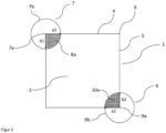
- FIG. 1 Such an exemplary metal sheet on which the measuring method according to the invention can be carried out is shown in Figure 1 illustrated.
- the illustrated metal sheet 1 has a front side 2. Opposite the front side 2 is the back side of the metal sheet. The front side 2 and the back side of the sheet are connected to one another via the side surfaces 3 and each have longitudinal edges 4, transverse edges 5 and corners 6 where the longitudinal edges 4 and transverse edges 5 meet.
- the longitudinal edges have a length L longitudinal edge of 50 mm to 2000 mm and/or the transverse edges have a length L transverse edge of 50 mm to 2000 mm.
- the front and back of the metal sheet can, for example, have a substantially square shape (ie L longitudinal edge and L transverse edge are the same or at least have very similar values) or alternatively have an elongated shape (ie L longitudinal edge and L transverse edge have significantly different values).
- the longitudinal edges and transverse edges of the For example, the front or back are essentially perpendicular to each other (e.g. at an angle of 90° +/- 10°).
- the metal sheet has a maximum thickness of 15 mm.
- the metal sheet is therefore a shaped body that has a significant extension in at least two spatial directions. Accordingly, there are in principle many ways in which the metal sheet can be contacted with the current source (or alternatively the voltage source) as part of a four-wire measurement to determine its electrical resistance.
- the four-wire measurement is carried out during the dispersion hardening of the metal sheet.
- the electrical resistance or an electrical quantity proportional to the electrical resistance, such as the electrical voltage or current
- the metal sheet is contacted with the current source (or alternatively the voltage source) in such a way that the first electrical contact surface is located relatively close to a first corner of the metal sheet, while the second electrical contact surface is located as close as possible to the corner that is the greatest distance from the first corner.
- the current source or alternatively the voltage source
- a1 and L longitudinal edge and b1 and L transverse edge satisfy the following relationships: a1 ⁇ 0 ,14 ⁇ L L Kunststoffskante und b1 ⁇ 0,14 ⁇ L Querkante
- a2 and L longitudinal edge and b2 and L transverse edge satisfy the following relationships: a2 ⁇ 0 ,14 ⁇ L L Kunststoffskante und b2 ⁇ 0,14 ⁇ L Querkante
- Figure 2 shows a top view of the front side 2 of the metal sheet 1, wherein the longitudinal edge 4 and transverse edge 5 of the front side 2 have the same length and meet in the corners 6.
- the cylinder axis 7a of the imaginary first cylinder 7 runs through one of the corners 6 and is perpendicular to the front side 2 of the metal sheet 1.
- the front side 2 intersects the imaginary first cylinder 7, obtaining a cutting surface 8a (hatched area in Figure 2 ).
- this cutting surface 8a there are other cutting surfaces (not shown in Figure 2 ) of the side surfaces and the back of the metal sheet with the imaginary first cylinder.
- the cylinder axis 9a of the imaginary second cylinder 9 is perpendicular to the front side 2 of the metal sheet 1 and runs through the corner 6 of the front side 2 which is the greatest distance from the corner 6 through which the cylinder axis 7a of the imaginary first cylinder 7 runs.
- the cylinder jacket 9b of the imaginary second cylinder intersects the longitudinal edge 4 at a distance a2 from the cylinder axis 9a and the longitudinal edge 5 at a distance b2 from the cylinder axis 9a.
- the intersection surface 10a of the front side 2 with the imaginary second cylinder is hatched.
- intersection surface there are other intersection surfaces (not shown in Figure 2 ) of the side surfaces and the back of the metal sheet with the imaginary second cylinder 9.
- the second electrical contact surface, via which the metal sheet is connected to the current or voltage source of the measuring arrangement, must be selected within these cutting surfaces.
- Figure 3 shows a plan view of the front side 2 of the metal sheet 1, wherein the longitudinal edge 4 and the transverse edge 5 of the front side 2 have significantly different lengths and meet in the corners 6.
- the front side 2 of the metal sheet 1 intersects the imaginary first cylinder 7 in the cutting surface 8a.
- the front side 2 of the metal sheet 1 intersects the imaginary second cylinder in the cutting surface 10a.
- the electrical contact surfaces by which the metal sheet is connected to the current or voltage source must be selected such that they each lie within an area consisting of the intersection surfaces of the front, back and side surfaces of the metal sheet with the imaginary first or second cylinder.
- the front side 2 of the metal sheet 1 intersects the imaginary first cylinder (not shown in Figure 4 ) in the cutting surface 8a and the imaginary second cylinder (not shown in Figure 4 ) in the cutting surface 10a.
- the side surfaces 3 intersect the first and second imaginary cylinders, among others, in the cutting surfaces 8b and 10b.
- the first electrical contact surface 11a for the connection to the power source 12 lies on the cutting surface 8b, while the second electrical contact surface (not shown in Figure 4 ) lies on an intersection of the opposite side surface with the imaginary second cylinder.
- the cutting surfaces 8a, 8b, 10a and 10b of the front 2 and the side surfaces 3 with the imaginary cylinders correspond to the Figure 4 shown cutting surfaces.
- the first electrical contact surface 11a for connection to the power source 12 is located within the cutting surface 8b.
- the second electrical contact surface 11b is located in the Figure 5 illustrated exemplary embodiment within the cutting surface 10a.
- a connection of the metal sheet to a voltage or current measuring device is established via a third electrical contact surface and a fourth electrical contact surface of the metal sheet. If the first and second electrical contact surfaces of the metal sheet are connected to a current source, the third and fourth electrical contact surfaces of the metal sheet are connected to a voltage measuring device. If the first and second electrical contact surfaces of the metal sheet are connected to a voltage source connected, the third and fourth electrical contact surface of the metal sheet is connected to an ammeter.
- Contact elements known to those skilled in the art can be used to connect the electrical contact surfaces of the metal sheet to the current or voltage source and the voltage or current measuring device.
- the electrical contact surfaces are connected to the current or voltage source and the voltage or current measuring device using terminals (e.g. Kelvin terminals or crocodile clips) or contact pins.
- Thermal dispersion hardening usually takes place at quite high temperatures and sometimes over quite long periods of time.
- the metal sheet is placed on the electrical lines, for example with one of its side surfaces.
- the number of contact terminals required can be significantly reduced.
- a suitable size for the electrical contact surfaces on the metal sheet can be determined by a person skilled in the art on the basis of his or her specialist knowledge or, if necessary, by routine tests.
- the electrical contact surfaces of the metal sheet each have an area of at least 1 mm 2 .
- the first electrical contact surface and the second electrical contact surface of the metal sheet are selected such that they each lie within an area consisting of the intersection surfaces of the front, back and side surfaces with the imaginary cylinders. This ensures that the first electrical contact surface is located relatively close to one of the corners of the metal sheet, while the second electrical contact surface is located as close as possible to the opposite corner.
- the positions of the third and fourth electrical contact surfaces on the metal sheet can be freely selected.
- the expert can determine suitable positions on the basis of his general specialist knowledge and, if necessary, through routine tests.
- the third and fourth electrical contact surfaces lie outside the intersection surfaces of the front, back and side surfaces with the imaginary first cylinder and outside the intersection surfaces of the front, back and side surfaces with the imaginary second cylinder.
- the third and fourth electrical contact surfaces are spaced apart by a distance that is smaller than the distance between the first and second electrical contact surfaces.
- the distance is the shortest straight connecting line between the two respective contact surfaces.
- first, third and fourth electrical contact surfaces are present on the same side surface of the metal sheet and the second electrical contact surface is present on another side surface, preferably the opposite side surface of the metal sheet.
- This exemplary embodiment is shown in Figure 6 illustrated.
- Figure 6 With regard to the cutting surfaces 8a, 8b, 10a and 10b of the front side 2 and the side surfaces 3 with the imaginary cylinders and the positions of the first electrical contact surface 11a and the second electrical contact surface (for the connection to the power source 12), Figure 6 the one in Figure 4 illustrated embodiment.
- the metal sheet 1 is connected to the voltage measuring device 14 via the electrical contact surfaces 13a and 13b.
- the metal sheet which is connected to the current or voltage source via the first and second electrical contact surfaces and to the voltage or current measuring device via the third and fourth electrical contact surfaces, is thermally treated so that oxide particles form in the metal sheet.
- Suitable metals in the form of alloys which form oxide particles during thermal treatment in an oxidizing atmosphere are known to the person skilled in the art.
- the metal from which the metal sheet is made is a precious metal alloy containing one or more non-precious metals.
- the precious metal alloy contains non-precious metals in a concentration of not more than 1% by weight and the remainder is one or more precious metals and unavoidable impurities.
- the non-precious metal is, for example, selected from zirconium, cerium, scandium and yttrium and the precious metal is, for example, selected from ruthenium, rhodium, gold, palladium, platinum, iridium and osmium.
- the precious metal alloy contains, for example, a first precious metal as the main element and other precious metals, if present, in a total concentration of no more than 29.95% by weight, provided that the first precious metal is different from the other precious metals.
- "Main element” means that this element is present in a higher concentration than each of the other elements.
- Suitable temperatures for carrying out dispersion hardening are known to the person skilled in the art or can be determined by routine tests.
- the thermal treatment of the metal sheet takes place at a temperature of at least 750°C, e.g. in the range from 750°C to 1400°C or 800°C to 1200°C.
- Dispersion hardening takes place in an oxidizing atmosphere.
- Suitable oxidizing atmospheres for dispersion hardening of alloys are known to those skilled in the art.
- the oxidizing atmosphere is an oxygen-containing atmosphere.
- the oxygen content of the oxidizing atmosphere is at least 5 vol%, more preferably at least 10 vol%.
- air is used as the oxidizing atmosphere.
- the electrical resistance or an electrical quantity proportional to the electrical resistance of the metal sheet is determined.
- the measured electrical resistance is influenced by the degree of oxidation of the metal sheet.
- the thermal treatment is terminated when the electrical resistance of the metal sheet shows a constant value (e.g. a maximum fluctuation of +/- 1%) over a specified period of time (e.g. at least 1 hour or at least 4 hours).
- a quantity proportional to the electrical resistance can be used to determine the required time for dispersion hardening. For example, it may be sufficient to measure the voltage or current at the third and fourth contact surfaces and to stop the thermal treatment when the voltage or current measured at these contact surfaces shows a constant value (e.g. a maximum fluctuation of +/- 1%) over a specified period of time (e.g. at least 1 hour or at least 4 hours).
- the determination of the electrical resistance or the electrical quantity proportional to it can, for example, be carried out continuously or at defined time intervals.
- ellipsoid also includes a sphere as a limiting case.
- the semiaxes a1, b1 and c1 of the imaginary first ellipsoid are usually perpendicular to each other.
- the semiaxes a2, b2 and c2 of the imaginary second ellipsoid are also usually perpendicular to each other.
- the shaped body is a metal tube
- the above-mentioned diameter D shaped body is the outer diameter of the metal tube.
- both the first end face and the second end face have an inner boundary line in addition to the outer boundary line.
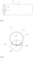
- FIG. 7 An exemplary metal pipe on which the measuring method according to the invention can be carried out is shown in Figure 7 illustrated.
- the illustrated metal tube 15 terminates at one of its ends with a first end face 16.
- the first end face 16 is delimited by an outer boundary line 18 and an inner boundary line 19.
- the outer boundary line 18 corresponds to the outer circumference of the tube 15, while the inner boundary line 19 corresponds to the inner circumference of the tube 15.
- the tube 15 terminates with a second end face (not shown in Figure 7 ), which is also limited by an outer and inner boundary line.
- the first end face 16 and the opposite second end face are connected to one another by the lateral surface 17.
- the metal tube or the metal rod for example, has a length L of 50 mm to 3000 mm.
- the metal tube or the metal rod has, for example, a ratio of L molded body to D molded body of at least 2, more preferably at least 5.
- the tube is, for example, a round tube or a polygonal tube (e.g. a square tube).
- a suitable wall thickness of the pipe depends, for example, on the intended use of the pipe.
- the pipe has a wall thickness to outer diameter ratio of at least 0.01.
- the pipe has a wall thickness of no more than 15 mm.
- Figure 8 shows the metal tube 15 in the direction of its longitudinal axis.
- the center 20a of the imaginary first ellipsoid 20 lies on the outer boundary line 18 of the first end face 16.
- the figure shows the semi-axes a1 and b1 of the ellipsoid 20.
- the first end face 16 intersects the imaginary first ellipsoid 20 in the intersection surface 21a.
- first end face 16 and the lateral surface 17 of the metal tube 15 intersect the imaginary first ellipsoid (not shown) in the intersection surfaces 21a and 21b.
- the lateral surface 17 intersects the imaginary second ellipsoid (not shown) in the intersection surface 23b.
- the intersection surface of the second end face with the imaginary second ellipsoid is in Figure 9 not shown.
- the first electrical contact surface 22a and the second electrical contact surface 22b lie within the cutting surfaces 21b and 23b and connect the metal tube 15 to the power source 12.
- a connection is made to a voltage or current measuring device via a third electrical contact surface and a fourth electrical contact surface of the metal molded body. If the first and second electrical contact surfaces of the metal rod or metal tube are connected to a power source, the third and fourth electrical contact surfaces of the metal rod or metal tube are connected to a voltage measuring device. If the first and second electrical contact surfaces of the metal rod or metal tube are connected to a voltage source, the third and fourth electrical contact surfaces of the metal rod or metal tube are connected to an current measuring device.
- Contact elements known to the person skilled in the art can be used to contact the electrical contact surfaces of the metal rod or metal tube with the current or voltage source and the voltage or current measuring device.
- the electrical contact surfaces are connected to the current or voltage source and the voltage or current measuring device via clamps (e.g. Kelvin clamps or crocodile clips).
- the first electrical contact surface is contacted with an electrical line of the current or voltage source and the third and fourth electrical contact surface are contacted with the electrical lines of the voltage or current measuring device under the influence of the gravity of the metal rod or metal tube, for example by placing or placing the metal rod or metal tube (e.g. with its outer surface or one of its end faces) on the electrical lines.
- the number of contact terminals required can be significantly reduced.
- a suitable size of the electrical contact surfaces on the metal rod or metal tube can be determined by a person skilled in the art on the basis of his or her specialist knowledge and through routine tests.
- the electrical contact surfaces of the metal rod or metal tube each have an area of at least 1 mm 2 .
- the first electrical contact surface and the second electrical contact surface of the metal rod or metal tube are selected such that they each lie within an area consisting of the intersection surfaces of the end face and the lateral surface with imaginary first or second ellipsoid. This ensures that the first electrical contact surface and the second electrical contact surface are as far apart as possible.
- intersection areas of the lateral surface and first end face with the imaginary first ellipsoid are the areas of the lateral surface and first end face that lie within the imaginary first ellipsoid.
- the intersection areas of the lateral surface and second end face with the imaginary second ellipsoid are the areas of the lateral surface and second end face that lie within the imaginary second ellipsoid.
- the positions of the third and fourth electrical contact surfaces on the metal tube or metal rod can be freely selected.
- the expert can determine suitable positions on the basis of his general specialist knowledge and, if necessary, by routine tests.
- the third and fourth electrical contact surfaces lie outside the intersection areas of the end faces and lateral surface with the imaginary ellipsoids.
- the third and fourth electrical contact surfaces are spaced apart by a distance that is smaller than the distance between the first and second electrical contact surfaces.
- the distance is the shortest straight connecting line between the two respective electrical contact surfaces.
- the cutting surfaces 21a, 21b and 23b and the electrical contact surfaces 22a and 22b correspond to the Figure 9 illustrated embodiment.
- the third electrical contact surface 24a and fourth electrical contact surface 24b, via which the metal tube 15 is connected to the voltage measuring device 14, are substantially linear to the first electrical Contact surface 22a is arranged. This can be achieved, for example, by laying or placing the metal tube 15 with its outer surface 17 on the electrical lines that are connected to the power source and the voltage measuring device.
- the metallic molded body which is connected to the current or voltage source via its first and second electrical contact surfaces and to the voltage or current measuring device via its third and fourth electrical contact surfaces, is thermally treated so that oxide particles form in the metal tube, and during the thermal treatment of the metallic molded body its electrical resistance or an electrical quantity proportional to the electrical resistance is determined.
- the present invention also relates to the use of the measuring arrangements described above for determining the duration of thermal dispersion hardening of the metal sheet, metal rod or metal tube.
- the dispersion hardening was carried out in an air atmosphere at a temperature of 1000°C.
- dispersion hardening is to oxidize the base metals of the alloy as completely as possible (with the formation of oxide particles dispersed in the precious metal matrix).
- the electrical resistance was determined as a function of time during dispersion hardening using a four-wire measurement. However, as described in more detail below, different measuring arrangements were used for the four-wire measurement.
- the measuring arrangements of the comparative example and the example according to the invention differed in the relative arrangement of the first and second electrical contact surfaces to each other.
- the first electrical contact surface was located on one of the side surfaces near a first corner of the sheet and the second electrical contact surface was located on the same side surface near the corner adjacent to the first corner.
- Distance of the first electrical contact surface from the first corner 15 mm
- Distance of the second electrical contact surface from the corner adjacent to the first corner 15 mm
- the position of the second electrical contact surface was changed so that it was located on the opposite side surface near the corner opposite the first corner.
- Distance of the second electrical contact surface from the opposite corner 15 mm
- Figure 6 shows a schematic representation of the measuring arrangement used in the example according to the invention.
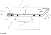
- FIG. 11 A schematic representation of the measuring arrangement of the comparison example shows the Figure 11 .
- the voltage source 14 is connected to the metal sheet 1 via the third and fourth electrical contact surfaces 13a and 13b.
- the current source 12 is connected to the metal sheet via the first and second electrical contact surfaces 11a and 11b.
- the second electrical contact surface 11b is not present on one of the intersection surfaces of the front, back or side surfaces of the metal sheet with the imaginary second cylinder.
- the measuring arrangement of the comparison example resulted in a constant resistance value after 60 hours.
- the oxygen content of both sheets was determined by quantitative IR spectroscopy using a LECO device (ONH836). Further details on this method can be found in EP 3 971 311 B1 If the chemical composition of the alloy is known, the degree of oxidation can be calculated from the measured oxygen. The degree of oxidation indicates the proportion of the non-precious metals that were converted into the corresponding oxides during dispersion hardening. A value as close to 100% as possible would be desirable.
- the data show that the measuring arrangement according to the invention allows the time required for dispersion hardening to be determined much more reliably.
Landscapes
- Chemical & Material Sciences (AREA)
- Physics & Mathematics (AREA)
- General Physics & Mathematics (AREA)
- Life Sciences & Earth Sciences (AREA)
- Health & Medical Sciences (AREA)
- Pathology (AREA)
- Immunology (AREA)
- General Health & Medical Sciences (AREA)
- Biochemistry (AREA)
- Analytical Chemistry (AREA)
- Electrochemistry (AREA)
- Chemical Kinetics & Catalysis (AREA)
- Engineering & Computer Science (AREA)
- Organic Chemistry (AREA)
- Metallurgy (AREA)
- Materials Engineering (AREA)
- Mechanical Engineering (AREA)
- Crystallography & Structural Chemistry (AREA)
- Thermal Sciences (AREA)
- Food Science & Technology (AREA)
- Medicinal Chemistry (AREA)
- Investigating Or Analyzing Materials By The Use Of Electric Means (AREA)
Priority Applications (3)
| Application Number | Priority Date | Filing Date | Title |
|---|---|---|---|
| EP23185034.8A EP4492048A1 (fr) | 2023-07-12 | 2023-07-12 | Procédé de détermination de la durée de durcissement d'une dispersion méthode de mesure d'une propriété électrique pour déterminer la durée de durcissement d'une dispersion d'une pièce moulée contenant du métal |
| CN202410790668.4A CN119310141A (zh) | 2023-07-12 | 2024-06-19 | 用于确定弥散硬化的持续时间的方法 |
| US18/769,627 US20250020706A1 (en) | 2023-07-12 | 2024-07-11 | Method for determining the duration of dispersion hardening |
Applications Claiming Priority (1)
| Application Number | Priority Date | Filing Date | Title |
|---|---|---|---|
| EP23185034.8A EP4492048A1 (fr) | 2023-07-12 | 2023-07-12 | Procédé de détermination de la durée de durcissement d'une dispersion méthode de mesure d'une propriété électrique pour déterminer la durée de durcissement d'une dispersion d'une pièce moulée contenant du métal |
Publications (1)
| Publication Number | Publication Date |
|---|---|
| EP4492048A1 true EP4492048A1 (fr) | 2025-01-15 |
Family
ID=87280476
Family Applications (1)
| Application Number | Title | Priority Date | Filing Date |
|---|---|---|---|
| EP23185034.8A Pending EP4492048A1 (fr) | 2023-07-12 | 2023-07-12 | Procédé de détermination de la durée de durcissement d'une dispersion méthode de mesure d'une propriété électrique pour déterminer la durée de durcissement d'une dispersion d'une pièce moulée contenant du métal |
Country Status (3)
| Country | Link |
|---|---|
| US (1) | US20250020706A1 (fr) |
| EP (1) | EP4492048A1 (fr) |
| CN (1) | CN119310141A (fr) |
Citations (15)
| Publication number | Priority date | Publication date | Assignee | Title |
|---|---|---|---|---|
| US2636819A (en) | 1951-01-31 | 1953-04-28 | Baker & Co Inc | Grain stabilizing metals and alloys |
| GB1280815A (en) | 1968-07-12 | 1972-07-05 | Johnson Matthey Co Ltd | Improvements in and relating to the dispersion strengthening of metals |
| GB1340076A (en) | 1970-01-23 | 1973-12-05 | Johnson Matthey Co Ltd | Dispersion strengthening of platinum group metals platinum group metal based alloys gold and gold based alloys |
| DE2355122A1 (de) | 1973-11-01 | 1975-05-07 | Scm Corp | Dispersionsverfestigte metalle |
| WO1981001013A1 (fr) | 1979-10-04 | 1981-04-16 | Owens Corning Fiberglass Corp | Traitement thermo-mecanique d'alliages de metaux precieux durcis par dispersion |
| GB2082205A (en) | 1980-08-14 | 1982-03-03 | Degussa | Dispersion-hardened platinum- group metal articles |
| US4507156A (en) | 1984-04-09 | 1985-03-26 | Owens-Corning Fiberglas Corporation | Creep resistant dispersion strengthened metals |
| EP0683240A2 (fr) | 1994-05-19 | 1995-11-22 | Schott Glaswerke | Procédé de préparation de matériaux, ébauches et tôles en platine pure renforcée par dispersion d'oxyde d'Yltrium |
| EP0870844A1 (fr) | 1997-04-08 | 1998-10-14 | W.C. Heraeus GmbH | Alliage de platine renforcé par dispersion d'oxydes et procedé de sa fabrication |
| EP0947595A2 (fr) | 1998-03-28 | 1999-10-06 | W.C. Heraeus GmbH & Co. KG | Procédé de préparation d'un article soudé, en particulier un tube, en matériau à base de platine renforcé par dispersion |
| EP1188844A1 (fr) | 2000-09-18 | 2002-03-20 | W.C. Heraeus GmbH & Co. KG | Alliage de platine non contenant pas d'or renforcé par dispersion d'oxydes petites et non-noble |
| EP1295953A1 (fr) | 2000-06-28 | 2003-03-26 | Tanaka Kikinzoku Kogyo Kabushiki Kaisha | Procede de production d'un materiau de platine renforce au moyen d'oxyde disperse |
| EP1964938A1 (fr) | 2007-02-14 | 2008-09-03 | W.C. Heraeus GmbH | Matière première platine, platine Rh- ou platine Au fabriquée par oxydation interne, durcie par dispersion d'oxyde et ayant une teneur élevée en oxyde et une bonne ductilité |
| WO2015082630A1 (fr) | 2013-12-06 | 2015-06-11 | Heraeus Deutschland GmbH & Co. KG | Procédé de traitement de compositions de platines durcies par dispersion |
| EP3971311B1 (fr) | 2020-09-17 | 2022-07-06 | Heraeus Deutschland GmbH & Co. KG | Alliage de métaux précieux durci par dispersion amélioré |
-
2023
- 2023-07-12 EP EP23185034.8A patent/EP4492048A1/fr active Pending
-
2024
- 2024-06-19 CN CN202410790668.4A patent/CN119310141A/zh active Pending
- 2024-07-11 US US18/769,627 patent/US20250020706A1/en active Pending
Patent Citations (15)
| Publication number | Priority date | Publication date | Assignee | Title |
|---|---|---|---|---|
| US2636819A (en) | 1951-01-31 | 1953-04-28 | Baker & Co Inc | Grain stabilizing metals and alloys |
| GB1280815A (en) | 1968-07-12 | 1972-07-05 | Johnson Matthey Co Ltd | Improvements in and relating to the dispersion strengthening of metals |
| GB1340076A (en) | 1970-01-23 | 1973-12-05 | Johnson Matthey Co Ltd | Dispersion strengthening of platinum group metals platinum group metal based alloys gold and gold based alloys |
| DE2355122A1 (de) | 1973-11-01 | 1975-05-07 | Scm Corp | Dispersionsverfestigte metalle |
| WO1981001013A1 (fr) | 1979-10-04 | 1981-04-16 | Owens Corning Fiberglass Corp | Traitement thermo-mecanique d'alliages de metaux precieux durcis par dispersion |
| GB2082205A (en) | 1980-08-14 | 1982-03-03 | Degussa | Dispersion-hardened platinum- group metal articles |
| US4507156A (en) | 1984-04-09 | 1985-03-26 | Owens-Corning Fiberglas Corporation | Creep resistant dispersion strengthened metals |
| EP0683240A2 (fr) | 1994-05-19 | 1995-11-22 | Schott Glaswerke | Procédé de préparation de matériaux, ébauches et tôles en platine pure renforcée par dispersion d'oxyde d'Yltrium |
| EP0870844A1 (fr) | 1997-04-08 | 1998-10-14 | W.C. Heraeus GmbH | Alliage de platine renforcé par dispersion d'oxydes et procedé de sa fabrication |
| EP0947595A2 (fr) | 1998-03-28 | 1999-10-06 | W.C. Heraeus GmbH & Co. KG | Procédé de préparation d'un article soudé, en particulier un tube, en matériau à base de platine renforcé par dispersion |
| EP1295953A1 (fr) | 2000-06-28 | 2003-03-26 | Tanaka Kikinzoku Kogyo Kabushiki Kaisha | Procede de production d'un materiau de platine renforce au moyen d'oxyde disperse |
| EP1188844A1 (fr) | 2000-09-18 | 2002-03-20 | W.C. Heraeus GmbH & Co. KG | Alliage de platine non contenant pas d'or renforcé par dispersion d'oxydes petites et non-noble |
| EP1964938A1 (fr) | 2007-02-14 | 2008-09-03 | W.C. Heraeus GmbH | Matière première platine, platine Rh- ou platine Au fabriquée par oxydation interne, durcie par dispersion d'oxyde et ayant une teneur élevée en oxyde et une bonne ductilité |
| WO2015082630A1 (fr) | 2013-12-06 | 2015-06-11 | Heraeus Deutschland GmbH & Co. KG | Procédé de traitement de compositions de platines durcies par dispersion |
| EP3971311B1 (fr) | 2020-09-17 | 2022-07-06 | Heraeus Deutschland GmbH & Co. KG | Alliage de métaux précieux durci par dispersion amélioré |
Non-Patent Citations (5)
| Title |
|---|
| "ASM International", vol. 2, 2011, article "Metallurgy for the Non-Metallurgisf", pages: 69 - 70 |
| COSOVIC VLADAN ET AL: "Improving dispersion of SnO2nanoparticles in Ag-SnO2electrical contact materials using template me", JOURNAL OF ALLOYS AND COMPOUNDS, ELSEVIER SEQUOIA, LAUSANNE, CH, vol. 567, 21 March 2013 (2013-03-21), pages 33 - 39, XP028586591, ISSN: 0925-8388, DOI: 10.1016/J.JALLCOM.2013.03.094 * |
| G. GOTTSTEIN: "Materialwissenschaft und Werkstofftechnik- Physikalische Grundlagen", vol. 4, 2014, SPRINGERVIEWEG, pages: 276 |
| M. BRUNCKO ET AL.: "In-situ monitoring of internal oxidation ofdilute alloys", CORROSION SCIENCE, vol. 49, 2007, pages 1228 - 1244, XP005793482, DOI: 10.1016/j.corsci.2006.06.031 |
| W.D. CALLISTERD.G. RETHWISCH: "Materials Science and Engineering - An Introduction", vol. 10, 2018, WILEY, pages: 571 |
Also Published As
| Publication number | Publication date |
|---|---|
| CN119310141A (zh) | 2025-01-14 |
| US20250020706A1 (en) | 2025-01-16 |
Similar Documents
| Publication | Publication Date | Title |
|---|---|---|
| DE112015002494B4 (de) | Brennstoffzellen-Separatormaterial und Verfahren zum Herstellen des Materials | |
| DE3827505C2 (fr) | ||
| DE3523047A1 (de) | Verfahren zur herstellung von kupfer-beryllium-legierungen | |
| DE102020133120A1 (de) | Kompositpartikel und verfahren zur herstellung von kompositpartikeln | |
| DE112016001058T5 (de) | Gassensorelement und Gassensor | |
| EP3960890A1 (fr) | Alliage palladium-cuivre-argent-ruthénium | |
| EP3971311B1 (fr) | Alliage de métaux précieux durci par dispersion amélioré | |
| DE112020004885T5 (de) | Geschweisstes bauteil mit ausgezeichneterspannungskorrosionsrissbeständigkeit und verfahren zur herstellung desselben | |
| DE4036273C2 (de) | Verfahren zur Bearbeitung eines Sauerstoffkonzentrations-Sensors durch Zuführung von Wechselstrom und derart bearbeiteter Sensor | |
| DE112020001421T5 (de) | Elektrischer widerstand, wabenstruktur, und elektrisch beheizte katalysatorvorrichtung | |
| DE1533371C3 (de) | Pulvergemisch zur Herstellung von dispersionsverfestigten Nickel-Chrom-Legierungen und Verfahren zur Herstellung derselben | |
| DE3522118A1 (de) | Verfahren zur herstellung von kupfer-beryllium-legierungsmaterial sowie danach hergestellte teile | |
| EP4492048A1 (fr) | Procédé de détermination de la durée de durcissement d'une dispersion méthode de mesure d'une propriété électrique pour déterminer la durée de durcissement d'une dispersion d'une pièce moulée contenant du métal | |
| EP2662465B1 (fr) | Alliage de rhodium pour la fabrication d'un fil pour des aiguilles de test | |
| DE112021004562T5 (de) | Widerstandslegierung zur verwendung in einem shunt-widerstand, verwendung einer widerstandslegierung in einem shunt-widerstand und shunt-widerstand mit einer widerstandslegierung | |
| DE2343278A1 (de) | Wolframfaden | |
| CH668837A5 (de) | Messelektrode zur ph-messung. | |
| EP1915765A1 (fr) | Materiau a base de carbone-argent, et procede pour le produire | |
| DE112018005222T5 (de) | Festelektrolyt, verfahren zu dessen herstellung und gassensor | |
| DE102004012386A1 (de) | Verbundhalbzeug aus einer Kupferlegierung, Herstellungsverfahren und Verwendung | |
| DE102016206445B4 (de) | Coulometrischer Feuchtesensor mit gelförmigem Elektrolyt und Herstellungsverfahren für einen Coulometrischen Feuchtesensor mit gelförmigem Elektrolyt | |
| DE2825424C2 (de) | Siliciumhaltiges Tantalpulver, Verfahren zu seiner Herstellung und seine Verwendung | |
| DE112020003625T5 (de) | Gassensorelement und Gassensor | |
| DE102020118373B4 (de) | Mehrlagige Ringelektrode mit mehreren Öffnungen und niedrigschmelzenden Innenstrukturen | |
| DE2554019B2 (de) | Feuchtigkeitsfühler |
Legal Events
| Date | Code | Title | Description |
|---|---|---|---|
| PUAI | Public reference made under article 153(3) epc to a published international application that has entered the european phase |
Free format text: ORIGINAL CODE: 0009012 |
|
| STAA | Information on the status of an ep patent application or granted ep patent |
Free format text: STATUS: REQUEST FOR EXAMINATION WAS MADE |
|
| 17P | Request for examination filed |
Effective date: 20230712 |
|
| AK | Designated contracting states |
Kind code of ref document: A1 Designated state(s): AL AT BE BG CH CY CZ DE DK EE ES FI FR GB GR HR HU IE IS IT LI LT LU LV MC ME MK MT NL NO PL PT RO RS SE SI SK SM TR |