EP4492097A1 - Verfahren zur bestimmung einer trajektorie eines mobilen trägers in echtzeit und in der zeitdifferenz - Google Patents
Verfahren zur bestimmung einer trajektorie eines mobilen trägers in echtzeit und in der zeitdifferenz Download PDFInfo
- Publication number
- EP4492097A1 EP4492097A1 EP24188465.9A EP24188465A EP4492097A1 EP 4492097 A1 EP4492097 A1 EP 4492097A1 EP 24188465 A EP24188465 A EP 24188465A EP 4492097 A1 EP4492097 A1 EP 4492097A1
- Authority
- EP
- European Patent Office
- Prior art keywords
- trajectory
- fus
- confidence
- merged
- determined
- Prior art date
- Legal status (The legal status is an assumption and is not a legal conclusion. Google has not performed a legal analysis and makes no representation as to the accuracy of the status listed.)
- Pending
Links
- 238000000034 method Methods 0.000 title claims abstract description 45
- 238000001514 detection method Methods 0.000 claims abstract description 13
- 238000012937 correction Methods 0.000 claims description 43
- 230000009466 transformation Effects 0.000 claims description 21
- 238000004364 calculation method Methods 0.000 claims description 6
- 230000011218 segmentation Effects 0.000 claims description 5
- 230000006798 recombination Effects 0.000 claims description 4
- 238000005215 recombination Methods 0.000 claims description 4
- 238000013519 translation Methods 0.000 claims description 4
- 238000005259 measurement Methods 0.000 description 38
- 230000004927 fusion Effects 0.000 description 21
- 238000012545 processing Methods 0.000 description 7
- 230000004807 localization Effects 0.000 description 5
- 238000013459 approach Methods 0.000 description 4
- 238000010586 diagram Methods 0.000 description 4
- 238000006073 displacement reaction Methods 0.000 description 4
- 230000000694 effects Effects 0.000 description 4
- 238000012805 post-processing Methods 0.000 description 4
- 230000003111 delayed effect Effects 0.000 description 3
- 239000011159 matrix material Substances 0.000 description 3
- 238000012958 reprocessing Methods 0.000 description 3
- 238000000844 transformation Methods 0.000 description 3
- 230000001133 acceleration Effects 0.000 description 2
- 238000009825 accumulation Methods 0.000 description 2
- 230000005540 biological transmission Effects 0.000 description 2
- 238000010168 coupling process Methods 0.000 description 2
- 238000005859 coupling reaction Methods 0.000 description 2
- 238000013507 mapping Methods 0.000 description 2
- 230000008569 process Effects 0.000 description 2
- 238000012360 testing method Methods 0.000 description 2
- 238000007476 Maximum Likelihood Methods 0.000 description 1
- 230000001594 aberrant effect Effects 0.000 description 1
- 230000003466 anti-cipated effect Effects 0.000 description 1
- 238000010420 art technique Methods 0.000 description 1
- 210000004027 cell Anatomy 0.000 description 1
- 230000008859 change Effects 0.000 description 1
- 230000008878 coupling Effects 0.000 description 1
- 230000003247 decreasing effect Effects 0.000 description 1
- 238000005516 engineering process Methods 0.000 description 1
- 238000007667 floating Methods 0.000 description 1
- 230000000670 limiting effect Effects 0.000 description 1
- 230000003287 optical effect Effects 0.000 description 1
- 230000008520 organization Effects 0.000 description 1
- 230000000750 progressive effect Effects 0.000 description 1
- 230000002829 reductive effect Effects 0.000 description 1
- 230000002441 reversible effect Effects 0.000 description 1
- 230000000087 stabilizing effect Effects 0.000 description 1
- 230000003068 static effect Effects 0.000 description 1
- 238000006467 substitution reaction Methods 0.000 description 1
- 230000002123 temporal effect Effects 0.000 description 1
- 238000011282 treatment Methods 0.000 description 1
- 230000001960 triggered effect Effects 0.000 description 1
Images




Classifications
-
- G—PHYSICS
- G01—MEASURING; TESTING
- G01S—RADIO DIRECTION-FINDING; RADIO NAVIGATION; DETERMINING DISTANCE OR VELOCITY BY USE OF RADIO WAVES; LOCATING OR PRESENCE-DETECTING BY USE OF THE REFLECTION OR RERADIATION OF RADIO WAVES; ANALOGOUS ARRANGEMENTS USING OTHER WAVES
- G01S19/00—Satellite radio beacon positioning systems; Determining position, velocity or attitude using signals transmitted by such systems
- G01S19/38—Determining a navigation solution using signals transmitted by a satellite radio beacon positioning system
- G01S19/39—Determining a navigation solution using signals transmitted by a satellite radio beacon positioning system the satellite radio beacon positioning system transmitting time-stamped messages, e.g. GPS [Global Positioning System], GLONASS [Global Orbiting Navigation Satellite System] or GALILEO
- G01S19/40—Correcting position, velocity or attitude
-
- G—PHYSICS
- G01—MEASURING; TESTING
- G01C—MEASURING DISTANCES, LEVELS OR BEARINGS; SURVEYING; NAVIGATION; GYROSCOPIC INSTRUMENTS; PHOTOGRAMMETRY OR VIDEOGRAMMETRY
- G01C21/00—Navigation; Navigational instruments not provided for in groups G01C1/00 - G01C19/00
- G01C21/10—Navigation; Navigational instruments not provided for in groups G01C1/00 - G01C19/00 by using measurements of speed or acceleration
- G01C21/12—Navigation; Navigational instruments not provided for in groups G01C1/00 - G01C19/00 by using measurements of speed or acceleration executed aboard the object being navigated; Dead reckoning
- G01C21/16—Navigation; Navigational instruments not provided for in groups G01C1/00 - G01C19/00 by using measurements of speed or acceleration executed aboard the object being navigated; Dead reckoning by integrating acceleration or speed, i.e. inertial navigation
- G01C21/165—Navigation; Navigational instruments not provided for in groups G01C1/00 - G01C19/00 by using measurements of speed or acceleration executed aboard the object being navigated; Dead reckoning by integrating acceleration or speed, i.e. inertial navigation combined with non-inertial navigation instruments
- G01C21/1652—Navigation; Navigational instruments not provided for in groups G01C1/00 - G01C19/00 by using measurements of speed or acceleration executed aboard the object being navigated; Dead reckoning by integrating acceleration or speed, i.e. inertial navigation combined with non-inertial navigation instruments with ranging devices, e.g. LIDAR or RADAR
-
- G—PHYSICS
- G01—MEASURING; TESTING
- G01C—MEASURING DISTANCES, LEVELS OR BEARINGS; SURVEYING; NAVIGATION; GYROSCOPIC INSTRUMENTS; PHOTOGRAMMETRY OR VIDEOGRAMMETRY
- G01C21/00—Navigation; Navigational instruments not provided for in groups G01C1/00 - G01C19/00
- G01C21/10—Navigation; Navigational instruments not provided for in groups G01C1/00 - G01C19/00 by using measurements of speed or acceleration
- G01C21/12—Navigation; Navigational instruments not provided for in groups G01C1/00 - G01C19/00 by using measurements of speed or acceleration executed aboard the object being navigated; Dead reckoning
- G01C21/16—Navigation; Navigational instruments not provided for in groups G01C1/00 - G01C19/00 by using measurements of speed or acceleration executed aboard the object being navigated; Dead reckoning by integrating acceleration or speed, i.e. inertial navigation
- G01C21/165—Navigation; Navigational instruments not provided for in groups G01C1/00 - G01C19/00 by using measurements of speed or acceleration executed aboard the object being navigated; Dead reckoning by integrating acceleration or speed, i.e. inertial navigation combined with non-inertial navigation instruments
-
- G—PHYSICS
- G01—MEASURING; TESTING
- G01S—RADIO DIRECTION-FINDING; RADIO NAVIGATION; DETERMINING DISTANCE OR VELOCITY BY USE OF RADIO WAVES; LOCATING OR PRESENCE-DETECTING BY USE OF THE REFLECTION OR RERADIATION OF RADIO WAVES; ANALOGOUS ARRANGEMENTS USING OTHER WAVES
- G01S19/00—Satellite radio beacon positioning systems; Determining position, velocity or attitude using signals transmitted by such systems
- G01S19/38—Determining a navigation solution using signals transmitted by a satellite radio beacon positioning system
- G01S19/39—Determining a navigation solution using signals transmitted by a satellite radio beacon positioning system the satellite radio beacon positioning system transmitting time-stamped messages, e.g. GPS [Global Positioning System], GLONASS [Global Orbiting Navigation Satellite System] or GALILEO
- G01S19/42—Determining position
- G01S19/43—Determining position using carrier phase measurements, e.g. kinematic positioning; using long or short baseline interferometry
-
- G—PHYSICS
- G01—MEASURING; TESTING
- G01S—RADIO DIRECTION-FINDING; RADIO NAVIGATION; DETERMINING DISTANCE OR VELOCITY BY USE OF RADIO WAVES; LOCATING OR PRESENCE-DETECTING BY USE OF THE REFLECTION OR RERADIATION OF RADIO WAVES; ANALOGOUS ARRANGEMENTS USING OTHER WAVES
- G01S19/00—Satellite radio beacon positioning systems; Determining position, velocity or attitude using signals transmitted by such systems
- G01S19/38—Determining a navigation solution using signals transmitted by a satellite radio beacon positioning system
- G01S19/39—Determining a navigation solution using signals transmitted by a satellite radio beacon positioning system the satellite radio beacon positioning system transmitting time-stamped messages, e.g. GPS [Global Positioning System], GLONASS [Global Orbiting Navigation Satellite System] or GALILEO
- G01S19/42—Determining position
- G01S19/45—Determining position by combining measurements of signals from the satellite radio beacon positioning system with a supplementary measurement
- G01S19/47—Determining position by combining measurements of signals from the satellite radio beacon positioning system with a supplementary measurement the supplementary measurement being an inertial measurement, e.g. tightly coupled inertial
-
- G—PHYSICS
- G01—MEASURING; TESTING
- G01S—RADIO DIRECTION-FINDING; RADIO NAVIGATION; DETERMINING DISTANCE OR VELOCITY BY USE OF RADIO WAVES; LOCATING OR PRESENCE-DETECTING BY USE OF THE REFLECTION OR RERADIATION OF RADIO WAVES; ANALOGOUS ARRANGEMENTS USING OTHER WAVES
- G01S19/00—Satellite radio beacon positioning systems; Determining position, velocity or attitude using signals transmitted by such systems
- G01S19/38—Determining a navigation solution using signals transmitted by a satellite radio beacon positioning system
- G01S19/39—Determining a navigation solution using signals transmitted by a satellite radio beacon positioning system the satellite radio beacon positioning system transmitting time-stamped messages, e.g. GPS [Global Positioning System], GLONASS [Global Orbiting Navigation Satellite System] or GALILEO
- G01S19/393—Trajectory determination or predictive tracking, e.g. Kalman filtering
Definitions
- the present invention relates to a method and a system for determining a trajectory of a mobile carrier.
- the technical field of the invention is that of localization by data fusion between data from a sensor with relative position information, such as an inertial navigation system (or INS for Inertial Navigation System), and data from a sensor with absolute position information, such as a satellite navigation system (or GNSS for Global Navigation Satellites System).
- a sensor with relative position information such as an inertial navigation system (or INS for Inertial Navigation System)
- INS Inertial Navigation System
- absolute position information such as a satellite navigation system (or GNSS for Global Navigation Satellites System).
- Localization systems using fusion allow to locate a mobile carrier such as a vehicle in a robust manner, even when the reception conditions of the GNSS signal deteriorate. Indeed, low-power GNSS signals are likely to be disturbed by intentional interference (jamming) or not (places not covered by GNSS signals).
- the localization system using INS/GNSS fusion allows to complete the missing information of the satellite system, by estimating the vehicle movements from the measurements of its accelerations (accelerometer) and angular velocities (gyrometer).
- accelerations accelerometer
- angular velocities gyrometer
- the recalibration can be anticipated and corrected before the drift occurs. Indeed, for certain applications a regular real-time trajectory, i.e. not including significant corrections, as well as a precise deferred-time trajectory, are necessary.
- SLAM Simultaneous Localization And Mapping
- Real-time GNSS/INS fusion algorithms and delayed-time GNSS/INS fusion algorithms are known in the state of the art.
- Real-time navigation systems combining the two inertial subsystems INS (Inertial Navigation System) and GNSS (Global Navigation Satellite System), rely on a fusion algorithm which classically belongs to the family of Kalman filters, as described in more detail in [1], or to its many derivatives such as Extended Kalman Filter (EKF), Error-State Kalman Filter (ES-KF), Unscented Kalman Filter (UKF), Interacting Multiple-Models Kalman Filter (IMM-KF).
- EKF Extended Kalman Filter
- ES-KF Error-State Kalman Filter
- UKF Unscented Kalman Filter
- IMM-KF Interacting Multiple-Models Kalman Filter
- this state vector can be formed for example by the position, the speed, the attitude angles, as well as the biases of the inertial sensors of the system considered.
- the algorithm estimates the errors of the quantities mentioned above in order to then apply the necessary corrections to them.
- This is a particular architecture called closed loop (cf. [1], 916), using a loose fusion (Loose coupling) and illustrated in the figure 2 .
- the relative position information sensor CR for example an inertial system, continuously calculates a solution notably composed of an estimate of attitude, position and speed (so-called APV solution), which is then compared, with regard to the position P and the speed V, to those from the absolute position information sensor CA, for example a GNSS receiver.
- APV solution an estimate of attitude, position and speed
- a trajectory corresponds to an APV solution.
- ⁇ eb e corresponds to the three angular corrections (x, y and z planes)
- ⁇ v eb e corresponds to the three speed corrections (x, y and z planes)
- ⁇ r eb e corresponds to the three position corrections (x, y and z planes)
- ⁇ b a corresponds to the three accelerometer bias corrections (x, y and z planes)
- ⁇ b g corresponds to the three gyrometer bias corrections (x, y and z planes).
- the algorithm also estimates the covariance P k associated with the solution which contains the precisions of the set of values that are tracked in the form of a matrix of dimensions m ⁇ m, where m represents the dimension of the state vector.
- angles, positions and velocities can use several different definitions for angles, positions and velocities, depending on the chosen reference frame (ECI, ECEF, ENU etc.), so the estimated angles are not necessarily the roll, pitch and yaw angles.
- the algorithm can also take into account a wide variety of other sources of information such as measurements from a magnetometer, odometer, barometer (altitude), etc.
- the temporal organization of the treatments is broken down into two sets operating at different rates, the relative position information sensor CR (typically the inertial unit), and the Kalman filter (P-EKF and M-EKF on the figure 2 ).
- the relative position information sensor CR operates at the high acquisition frequency of the inertial unit (f 1 , generally between 50 Hz and 2000 Hz, typically approximately equal to 200 Hz for certain inertial navigation systems).
- the processing is therefore initiated by the generation of a new measurement carried out by the inertial measurement unit (measurement by the accelerometer and by the gyrometer) at time t i , which is then processed in order to update the angles/position/speed of the APV solution.
- the Kalman filter processing is initiated by the provision of a new measurement/information, outside the inertial unit.
- this consists of a GNSS measurement, but for more complex systems it can also correspond to at least one of the following measurements: an Ultra Wide Band distance measurement, an odometric measurement, an altimetric measurement, the detection of a static phase (which is not a "measurement” strictly speaking, but falls into the category of "information”), the consideration of speed constraints, or even a radar measurement.
- Rauch-Tung-Streibel Smoother or “RTS-Smoother” and described in [2].
- This technique consists of reprocessing the entire data set (INS measurements, GNSS etc.) in increasing time order (i.e. as in real-time processing) to generate a first trajectory, then in decreasing time order to generate a second trajectory, then to calculate a solution that combines the two trajectories.
- the invention thus aims to provide a method for determining a trajectory of a mobile carrier, which calculates a merged trajectory in real time and regular and a precise and regular trajectory in deferred time, while limiting the flow of information as well as the backup capacity necessary for the trajectory in deferred time.
- the method further comprises a step S3) of segmenting the regularized trajectory into so-called high-confidence segments and so-called non-high-confidence segments, the segmentation being performed as a function of the confidence indicator associated with the merged data packet for each determined instant t k , and of determining a post-processed trajectory, the post-processed trajectory corresponding to the merged trajectory for each high-confidence segment, and the post-processed trajectory being determined, for each non-high-confidence segment, by a geometric transformation of the non-high-confidence segment such that a continuity condition is satisfied between each of its ends and the end of the adjacent high-confidence segment.
- the relative position information sensor comprises an inertial unit.
- the absolute position information sensor comprises a GNSS receiver supporting RTK mode, the confidence indicator being provided by the RTK value of the GNSS receiver, in particular the “RTK fix” value.
- the first step S1 comprises the calculation of a correction indicator which represents the difference between the data provided by the relative position information sensor and the data provided by the absolute position information sensor between two consecutive selected times t k- 1 and t k .
- the detection of a position jump includes the comparison of the correction indicator with a predetermined threshold.
- the predetermined threshold is determined based on the quality of the relative position information sensor.
- the geometric transformation comprises at least one translation or one rotation.
- the geometric transformation further includes a homothety when the non-high confidence segment is preceded or followed by a high confidence segment.
- R m cos ⁇ sin ⁇ 0 ⁇ sin ⁇ cos ⁇ 0 0 0 1
- step S3 further comprises a weighted recombination of the merged trajectory and the post-processed trajectory.
- steps S1 and S2 are executed in real time during the movement of the mobile carrier, and step S3 is executed in delayed time.
- the fixed device is further configured to segment the corrected trajectory into so-called high-confidence segments and so-called non-high-confidence segments, the segmentation being performed as a function of the confidence indicator associated with the data packet for each determined instant t k , and to determine a post-processed trajectory, the post-processed trajectory corresponding to the merged trajectory for each high-confidence segment, and the post-processed trajectory being determined, for each non-high-confidence segment, by a geometric transformation of the non-high-confidence segment such that a continuity condition is satisfied between each of its ends and the end of the adjacent high-confidence segment.
- the mobile device and the fixed device are connected to each other by a radio link.
- the method comprises a first step S1), which comprises determining a merged trajectory TrA of the mobile carrier at each instant t i .
- the merged trajectory TrA is obtained by merging data provided by at least one relative position information sensor CR with data provided by at least one absolute position information sensor CA.
- the relative position information sensor CR is an inertial navigation unit
- the absolute position information sensor CA is a satellite navigation receiver
- Other types of sensor may be considered, provided that data fusion between the sensors can be performed, that the absolute position information sensor CA can provide navigation information at the desired accuracy, and that the relative position information sensor CR can provide positioning information continuously, i.e. even when the absolute position information sensor CA is unable to provide location information.
- the absolute position information sensor CA can be a GNSS signal receiver, a UWB, WiFi, or 4G/5G radio wave transmitter/receiver terminal or any other equivalent technology.
- the relative position information sensor CR can be an odometer, or an optical flow sensor.
- an absolute position information sensor CA is a sensor that relies on an external element (for example a satellite or a telecommunications station).
- a relative position information sensor CR is a sensor that does not rely on an external element, thus likely to provide a position error that increases over time.
- the first step S1 can be implemented by a BFD block which generates the merged trajectory TrA in real time at a frequency f 1 , which corresponds to the generation frequency of the position information of the relative position information sensor CR (cf. figure 4 ).
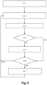
- FIG. 5 illustrates in more detail the sub-steps of the first step of the method according to the invention.
- the first sub-step S11 consists of obtaining an initialization of the APV solution, according to techniques known to those skilled in the art.
- the second sub-step S12 consists of receiving measurements from a relative position information sensor CR such as an inertial unit (three acceleration values provided by an accelerometer, three rotation speed values provided by a gyrometer), at each measurement instant t i .
- a relative position information sensor CR such as an inertial unit (three acceleration values provided by an accelerometer, three rotation speed values provided by a gyrometer), at each measurement instant t i .
- the algorithm calculates in real time an inertial solution APV(i) according to techniques known to those skilled in the art (third sub-step S13).
- the BFD block determines whether measurements from the absolute position information sensor CA such as a GPS system (examples position, speed, raw pseudo-range measurements) have been received (substep S14).
- the absolute position information sensor CA such as a GPS system
- a corrected inertial solution APV(i) is calculated according to techniques known to those skilled in the art (sub-step S15).
- the merged trajectory TrA of the mobile carrier is thus determined at each measurement instant t i on the basis of the corrected inertial solution APV(i).
- Substep S16 consists in determining whether the corrected inertial solution APV(i) calculated at the measurement instant t i belongs to the set of determined instants t k among the instants t i . This substep is also implemented as long as no measurement from the absolute position information sensor CA has been received.
- the determination of the instants t k can be implemented by decimating the count of the measurement instants t i , using a decimation counter which can be reloaded to a predetermined value Ndec, for example between 1 and 1000, preferably equal to 200, and which is decremented by one unit at each measurement instant t i .
- Ndec a predetermined value
- the counter reaches the value 0, it is reloaded and the substep S17 is executed.
- Substep S17 consists of generating a merged data packet.
- D k fus comprising merged data at the determined time t k and at least one confidence indicator c k fus associated with the data packet of the merged position at the determined time t k .
- the data packet contains for example: time t k , position p k fus , speed v k fus , the angles a k fus , one or more confidence indicators Iconf, a correction indicator Icorr.
- Some variables are vectorial and can therefore include several values. Since the invention aims to compensate for position deviations, it is essential that the data packet includes the position p k fus . Alternatively, the entire APV value set can be transmitted.
- the confidence indicator c k fus includes accuracy information of the data provided by the CA absolute position information sensor.
- the confidence indicator c k fus is provided by the RTK value of the GNSS receiver, in particular the “RTK fix” value.
- RTK Real Time Kinematic
- RTK uses a mathematical ambiguity resolution algorithm to calculate the exact number of radio wavelengths between the satellites and the ground station antenna and produce a fixed or floating solution.
- the number of wavelengths is an integer, which provides centimeter accuracy.
- the algorithm does not provide an acceptable fixed solution, so the ambiguity is allowed to be a decimal or floating-point number. Accuracy is typically sub-meter.
- the order of magnitude of accuracy is metric.
- confidence indicators can be calculated, such as, for example, indicators established from the coefficients of the covariance matrix of the solution calculated by the Kalman filter.
- the correction indicator represents the difference between the data provided by the relative position information sensor and the data provided by the absolute position information sensor between two consecutive selected times t k- 1 and t k .
- x i being here a component of the state vector xk defined previously, which can advantageously be the correction component of the position according to at least one of the three dimensions.
- correction indicators can be calculated, such as for example a sum of the standards which would only concern certain components. of the correction x i , such as the speed components, a distance between two successive positions, a statistic (mean deviation, variance, etc.) relating to the distance between successive positions established for all the positions calculated between two transmitted packets, or even the detection of particular phenomena (detection of odometer slippage, loss of GNSS signal, saturation of sensors, loss of data, etc.).
- a statistic mean deviation, variance, etc.
- a variant of the decimation of the counting of the measurement instants t i (substep S16) consists in calculating the time elapsed since the last execution of substep S17: if this time exceeds a predetermined duration, substep S17 is executed.
- substep S17 can be executed for each correction of the inertial position (triggered by the reception of a GNSS measurement for example).
- the merged trajectory TrA determined by the BFD block ( figure 4 ), is said to be precise and not regular because the navigation information is generated at high frequency but with jumps in the trajectory due to recalibration.
- the method comprises a second step S2 of determining a regularized trajectory TrB as a function of the detection of a position jump in the merged data packet.
- D k fus between the previous selected time t k- 1 and the selected time t k .
- the second sub-step S22 is to receive the merged data packet.
- D k fus comprising data merged at the determined time t k , at least one confidence indicator c k fus associated with the data packet of the merged position at the selected time t k , and possibly a correction indicator.
- the detection of a position jump advantageously comprises the comparison of the correction indicator contained in the data packet with a predetermined threshold Tsaut (sub-step S23): Icorr > Tsaut
- the predetermined threshold Tsaut can be between 0.01 and 10, this value being able to be determined according to the desired precision.
- the predetermined threshold Tsaut is determined according to the quality of the relative position information sensor. Indeed, with a very good quality inertial unit, it may be useful to set a relatively low Tsaut threshold, which implies a low tolerance to drifts of the inertial unit. Conversely, with a lower quality inertial unit, it may be useful to set a relatively high Tsaut threshold, which implies a high tolerance to drifts of the inertial unit.
- condition for detecting a position jump may relate to the successive violation of the thresholds, a violation of several thresholds simultaneously (for example a threshold linked to the sum of the position correction standards and a threshold linked to the sum of the speed correction standards, both thresholds having to be exceeded) or else undifferentiated (the exceeding of one of the two thresholds).
- substep S24 consists in updating the compensation ⁇ k if a jump was detected in substep S23.
- the second step S2 can be implemented by a trajectory correction block BCT, which generates the regularized trajectory TrB in real time (fig. 4).
- the regularized trajectory TrB is said to be regular and not precise because there is a coherence between the different positions of the trajectory, but it does not correspond to the precisely estimated trajectory (the position jumps having been compensated).
- the combination of the first two steps S1 and S2 makes it possible to calculate a trajectory in real time which is free of jumps, i.e. strong discontinuities according to the value of the jump detection threshold set, but also as precise as possible even in a degraded GNSS environment, thanks to the fusion of data from sensors with absolute position information and sensors with relative position information (GNSS/INS fusion for example).
- the regularized trajectory TrB can be very useful for the assembly of different shots (photogrammetry, radar imagery), which requires very precise relative positions between the different shots, which is not the case in the presence of a strong correction.
- the method according to the invention comprises a third optional step. It consists in calculating a post-processed trajectory TrC from the merged trajectory TrA, the regularized trajectory TrB, and the confidence indicators (cf. figure 4 ).
- the regularized trajectory TrB is cut into high-confidence segments S m FC , and in non-high confidence segments S m NFC .
- segment we mean a portion of a trajectory.
- the division is carried out according to the confidence indicator c k fus associated with the merged data package D k fus for each selected time t k .
- the post-processed trajectory TrC corresponds to the merged trajectory TrA for each high-confidence segment S m FC , i.e. the APV solution of the merged trajectory TrA.
- the post-processed trajectory TrC is determined by a geometric transformation of the non-high confidence segment S m NFC such that a continuity condition is satisfied between each of its ends and the end of the adjacent high-confidence segment.
- the post-processed trajectory TrC is regular in real time and regular and precise in delayed time in post-processing.
- the method according to the invention makes it possible to considerably limit the flow rate required between the mobile carrier and the fixed system responsible for calculating the post-processed trajectory, which also offers better robustness in the event of data loss during transmission.
- the use of state-of-the-art techniques for the calculation of the trajectory in deferred time would require storing the raw data of the sensors and transmitting them from the mobile device where they would be acquired, to the calculation means (a computer) where they would be processed.
- a radio link offering a useful rate of between 38.4 kb/s (three accelerometer data, three gyrometer data, coded on four bytes, with an acquisition frequency equal to 200 Hz) or 200 kb/s (with more sensors) would be necessary.
- the loss of data during transmission would have a significant effect on the reconstruction of the trajectory because this would lead to errors when calculating the inertial solution.
- the method according to the invention would make it possible to use a radio link at 0.9 kb/s or 3.84 kb/s depending on whether the position alone is transmitted, or the entire APV solution.
- a first sub-step S31 the packets, or points of the trajectory, stored in the backup means MS, are provided to the trajectory processing block BPT ( figure 4 ).
- the regularized trajectory TrB is cut into high-confidence segments S m FC , and in non-high confidence segments S m NFC .
- the packets for which the confidence indicator c k fus corresponds to the “RTK fix” value (within a plus or minus tolerance margin) are classified as high confidence segments S m FC , and packages whose trust indicator c k fus is too far from the “RTK fix” value (i.e. confidence indicator c k fus different from the “RTK fix” value with plus or minus the tolerance margin) are classified as non-high confidence segments S m NFC .
- segmentation can be performed without knowledge of the RTK value.
- the confidence indicator c k fus can be compared to a threshold. Additional test criteria can be added, such as comparing the confidence indicator c k fus with multiple thresholds, or the fact that a sufficient number of consecutive points must meet a condition to be classified as a high-confidence segment S m FC .
- a third sub-step S33 the corrected positions are calculated for all the points of each segment with non-high confidence.
- S m NFC as illustrated by the figure 8 .
- the first point of the segment S m NFC has index k m and the last point of the segment has index (k + l) m .
- the continuity condition between each endpoint of the non-high-confidence segment and the endpoint of the adjacent high-confidence segment implies that the position p k m reg must match the position p k m ⁇ 1 fus , and the position p k m + l reg must match the position p k m + l + 1 fus .
- the geometric transformation g m of the segment S m NFC is calculated such that the segment S m NFC coincides at its two ends ( p k m reg , p k m + l reg ) with the points of the neighboring segments with high confidence ( p k m ⁇ 1 fus , p k m + l + 1 fus ).
- the geometric transformation comprises at least one translation or one rotation, as well as one homothety when the non-strong segment confidence is preceded or followed by a high-confidence segment.
- the geometric transformation comprises at least one translation or one rotation, as well as one homothety when the non-strong segment confidence is preceded or followed by a high-confidence segment.
- H m ⁇ p k m reg ⁇ p k m + l reg ⁇ ⁇ p k m ⁇ 1 fus ⁇ p k m + l + 1 fus ⁇
- R m cos ⁇ sin ⁇ 0 ⁇ sin ⁇ cos ⁇ 0 0 0 1
- the continuity condition was defined with geometric transformations on the positions of the APV solution of the estimated trajectory.
- Other geometric transformations can be considered, for example by also taking into account the speed and angles resulting from the merger.
- the fourth sub-step S34 then consists of reconstructing the post-processed trajectory TrC (consisting of the positions p k pp ) from the merged positions and the corrected positions.
- substep S34 further comprises a weighted recombination of the merged trajectory TrA and the post-processed trajectory TrC.
- Weighted combination helps to limit the effect caused by a strong proximity between the starting point and the end point of the post-processed trajectory. Indeed, when the trajectory forms a "loop", a very small error on the position of the starting/end points is multiplied by the geometric transformation and the points in the middle of the loop can be highly erroneous. Weighted combination of positions helps to avoid such errors.
- the invention also relates to a system capable of implementing the predefined method.
- the system illustrated by the figure 9 , advantageously comprises a mobile device DM to be located and configured to calculate the merged trajectory TrA in real time.
- a mobile device DM comprises an absolute position information sensor CA, a relative position information sensor CR, and a calculation unit CPU comprising a data fusion block BFD.
- the system further comprises a fixed device DF, comprising a trajectory correction block BCT for calculating the regularized trajectory TrB in real time, and a post-processing block BPT for calculating the post-processed trajectory TrC in deferred time.
- a means of MS backup arranged in the fixed DF device, allows to store data packets before post-processing.
Landscapes
- Engineering & Computer Science (AREA)
- Radar, Positioning & Navigation (AREA)
- Remote Sensing (AREA)
- Physics & Mathematics (AREA)
- General Physics & Mathematics (AREA)
- Computer Networks & Wireless Communication (AREA)
- Automation & Control Theory (AREA)
- Navigation (AREA)
- Mobile Radio Communication Systems (AREA)
Applications Claiming Priority (1)
| Application Number | Priority Date | Filing Date | Title |
|---|---|---|---|
| FR2307495A FR3151088B1 (fr) | 2023-07-13 | 2023-07-13 | Procédé de détermination d’une trajectoire d’un porteur mobile en temps réel et en temps différé |
Publications (1)
| Publication Number | Publication Date |
|---|---|
| EP4492097A1 true EP4492097A1 (de) | 2025-01-15 |
Family
ID=89157865
Family Applications (1)
| Application Number | Title | Priority Date | Filing Date |
|---|---|---|---|
| EP24188465.9A Pending EP4492097A1 (de) | 2023-07-13 | 2024-07-12 | Verfahren zur bestimmung einer trajektorie eines mobilen trägers in echtzeit und in der zeitdifferenz |
Country Status (3)
| Country | Link |
|---|---|
| US (1) | US20250027774A1 (de) |
| EP (1) | EP4492097A1 (de) |
| FR (1) | FR3151088B1 (de) |
Families Citing this family (1)
| Publication number | Priority date | Publication date | Assignee | Title |
|---|---|---|---|---|
| CN121252823B (zh) * | 2025-12-05 | 2026-03-03 | 烟台欣飞智能系统有限公司 | 基于多源信息融合的无人机飞行轨迹定位方法及系统 |
Citations (4)
| Publication number | Priority date | Publication date | Assignee | Title |
|---|---|---|---|---|
| US20110187590A1 (en) * | 2008-10-06 | 2011-08-04 | Rodrigo Leandro | Position Estimation Methods and Apparatus |
| US20180039284A1 (en) * | 2016-08-04 | 2018-02-08 | Mitsubishi Electric Corporation | Vehicle position detector, automatic steering controller, vehicle position detecting method, and automatic steering control method |
| US20190187296A1 (en) | 2017-12-19 | 2019-06-20 | Pusan National University Industry-University Cooperation Foundation | Method and system for processing trajectory data |
| EP3701286A1 (de) * | 2017-10-26 | 2020-09-02 | Focal Point Positioning Limited | Verfahren und system zum kombinieren von sensordaten |
Family Cites Families (1)
| Publication number | Priority date | Publication date | Assignee | Title |
|---|---|---|---|---|
| US9719787B2 (en) | 2015-02-26 | 2017-08-01 | Invensense, Inc. | Method and system for multiple pass smoothing |
-
2023
- 2023-07-13 FR FR2307495A patent/FR3151088B1/fr active Active
-
2024
- 2024-07-12 US US18/770,798 patent/US20250027774A1/en active Pending
- 2024-07-12 EP EP24188465.9A patent/EP4492097A1/de active Pending
Patent Citations (4)
| Publication number | Priority date | Publication date | Assignee | Title |
|---|---|---|---|---|
| US20110187590A1 (en) * | 2008-10-06 | 2011-08-04 | Rodrigo Leandro | Position Estimation Methods and Apparatus |
| US20180039284A1 (en) * | 2016-08-04 | 2018-02-08 | Mitsubishi Electric Corporation | Vehicle position detector, automatic steering controller, vehicle position detecting method, and automatic steering control method |
| EP3701286A1 (de) * | 2017-10-26 | 2020-09-02 | Focal Point Positioning Limited | Verfahren und system zum kombinieren von sensordaten |
| US20190187296A1 (en) | 2017-12-19 | 2019-06-20 | Pusan National University Industry-University Cooperation Foundation | Method and system for processing trajectory data |
Non-Patent Citations (2)
| Title |
|---|
| H. E. RAUCHF. TUNGC. T. STRIEBEL: "Maximum likelihood estimates of linear dynamic systems", AIAA JOURNAL, vol. 3, no. 8, pages 1445 - 1450 |
| P. GROVES: "Principles of GNSS, Inertial and multisensor integrated navigation systems", 2013, ARTECH HOUSE |
Also Published As
| Publication number | Publication date |
|---|---|
| US20250027774A1 (en) | 2025-01-23 |
| FR3151088A1 (fr) | 2025-01-17 |
| FR3151088B1 (fr) | 2025-07-18 |
Similar Documents
| Publication | Publication Date | Title |
|---|---|---|
| EP3359915B1 (de) | Verfahren zur schätzung der bewegung eines fussgängers | |
| EP2225622B1 (de) | Verfahren zur flugzeuglandeunterstützung mithilfe von gps und mls im falle einer berechneten axial-annäherung | |
| EP2478334B1 (de) | Dreidimensionale ortung einer bestimmten landfläche mittels fusionierung von mit zwei satellitensensoren aufgenommenen bildern | |
| WO2015058986A1 (fr) | Procede de localisation en interieur et exterieur et dispositif portatif mettant en œuvre un tel procede. | |
| FR2964774A1 (fr) | Procede d'estimation du mouvement d'un porteur par rapport a un environnement et dispositif de calcul pour systeme de navigation | |
| EP2241856A1 (de) | Hybrides Trägheitssystem mit einem nichtlinearen Verhalten und entsprechendes Hybridisierungsverfahren auf der Basis einer multi-hypothesen Filterung | |
| EP4492097A1 (de) | Verfahren zur bestimmung einer trajektorie eines mobilen trägers in echtzeit und in der zeitdifferenz | |
| EP3447654A1 (de) | Bestimmungsverfahren der bewegungsbahn eines beweglichen objekts, programm und vorrichtung zur umsetzung dieses verfahrens | |
| EP3869155B1 (de) | Verfahren zur bestimmung der position und orientierung eines fahrzeugs | |
| EP2476015B1 (de) | Verfahren zur bestimmung der navigationsgeschwindigkeit eines trägers und hybridisierungsvorrichtung | |
| FR2906632A1 (fr) | Procede de localisation d'un vehicule. | |
| FR3075355B1 (fr) | Procede d'estimation de donnees de navigation d'un vehicule terrestre utilisant des parametres de geometrie et d'orientation de route | |
| WO2021156569A1 (fr) | Procede d'aide à la navigation d'un porteur mobile | |
| FR3106665A1 (fr) | Procédé et dispositif de localisation d’un véhicule | |
| EP2626725B1 (de) | Bestimmungsverfahren einer Verlässlichkeitsanzeige in Bezug auf die eingeschlagene Bewegungsbahn eines mobilen Geräts | |
| EP4184193B1 (de) | Verfahren zur bestimmung eines korrigierten abstandes | |
| EP4290267B1 (de) | Verfahren zur lokalisierung einer navigationseinheit | |
| EP4184208B1 (de) | Verfahren zur lokalisierung eines fahrzeugs | |
| FR3106886A1 (fr) | Détermination d’informations d’aide à la navigation sur un réseau routier | |
| FR3014556B1 (fr) | Procede et dispositif d'alignement d'une centrale inertielle | |
| EP3967975A1 (de) | Verfahren zur positionsbestimmung und orientierung eines fahrzeugs | |
| FR3041769A1 (fr) | Procede de geolocalisation | |
| FR3039342A1 (fr) | Procede et dispositif pour localiser des mobiles se deplacant en suivant une trajectoire predetermine | |
| EP4545909A1 (de) | Verfahren zur ausrichtung eines trägheitsnavigationssystems | |
| CN121977589A (en) | Multi-source fusion navigation method and system based on voxel map association and ground constraint |
Legal Events
| Date | Code | Title | Description |
|---|---|---|---|
| PUAI | Public reference made under article 153(3) epc to a published international application that has entered the european phase |
Free format text: ORIGINAL CODE: 0009012 |
|
| STAA | Information on the status of an ep patent application or granted ep patent |
Free format text: STATUS: REQUEST FOR EXAMINATION WAS MADE |
|
| 17P | Request for examination filed |
Effective date: 20240717 |
|
| AK | Designated contracting states |
Kind code of ref document: A1 Designated state(s): AL AT BE BG CH CY CZ DE DK EE ES FI FR GB GR HR HU IE IS IT LI LT LU LV MC ME MK MT NL NO PL PT RO RS SE SI SK SM TR |