EP4492126A1 - Linsenansteuerungsvorrichtung und kameramodul sowie optische vorrichtung damit - Google Patents
Linsenansteuerungsvorrichtung und kameramodul sowie optische vorrichtung damit Download PDFInfo
- Publication number
- EP4492126A1 EP4492126A1 EP23767125.0A EP23767125A EP4492126A1 EP 4492126 A1 EP4492126 A1 EP 4492126A1 EP 23767125 A EP23767125 A EP 23767125A EP 4492126 A1 EP4492126 A1 EP 4492126A1
- Authority
- EP
- European Patent Office
- Prior art keywords
- magnet
- housing
- bobbin
- cover member
- opening
- Prior art date
- Legal status (The legal status is an assumption and is not a legal conclusion. Google has not performed a legal analysis and makes no representation as to the accuracy of the status listed.)
- Pending
Links
Images









Classifications
-
- G—PHYSICS
- G02—OPTICS
- G02B—OPTICAL ELEMENTS, SYSTEMS OR APPARATUS
- G02B7/00—Mountings, adjusting means, or light-tight connections, for optical elements
- G02B7/02—Mountings, adjusting means, or light-tight connections, for optical elements for lenses
-
- G—PHYSICS
- G02—OPTICS
- G02B—OPTICAL ELEMENTS, SYSTEMS OR APPARATUS
- G02B27/00—Optical systems or apparatus not provided for by any of the groups G02B1/00 - G02B26/00, G02B30/00
- G02B27/64—Imaging systems using optical elements for stabilisation of the lateral and angular position of the image
-
- G—PHYSICS
- G02—OPTICS
- G02B—OPTICAL ELEMENTS, SYSTEMS OR APPARATUS
- G02B27/00—Optical systems or apparatus not provided for by any of the groups G02B1/00 - G02B26/00, G02B30/00
- G02B27/64—Imaging systems using optical elements for stabilisation of the lateral and angular position of the image
- G02B27/646—Imaging systems using optical elements for stabilisation of the lateral and angular position of the image compensating for small deviations, e.g. due to vibration or shake
-
- G—PHYSICS
- G02—OPTICS
- G02B—OPTICAL ELEMENTS, SYSTEMS OR APPARATUS
- G02B7/00—Mountings, adjusting means, or light-tight connections, for optical elements
- G02B7/02—Mountings, adjusting means, or light-tight connections, for optical elements for lenses
- G02B7/023—Mountings, adjusting means, or light-tight connections, for optical elements for lenses permitting adjustment
-
- G—PHYSICS
- G02—OPTICS
- G02B—OPTICAL ELEMENTS, SYSTEMS OR APPARATUS
- G02B7/00—Mountings, adjusting means, or light-tight connections, for optical elements
- G02B7/02—Mountings, adjusting means, or light-tight connections, for optical elements for lenses
- G02B7/04—Mountings, adjusting means, or light-tight connections, for optical elements for lenses with mechanism for focusing or varying magnification
- G02B7/08—Mountings, adjusting means, or light-tight connections, for optical elements for lenses with mechanism for focusing or varying magnification adapted to co-operate with a remote control mechanism
-
- G—PHYSICS
- G03—PHOTOGRAPHY; CINEMATOGRAPHY; ANALOGOUS TECHNIQUES USING WAVES OTHER THAN OPTICAL WAVES; ELECTROGRAPHY; HOLOGRAPHY
- G03B—APPARATUS OR ARRANGEMENTS FOR TAKING PHOTOGRAPHS OR FOR PROJECTING OR VIEWING THEM; APPARATUS OR ARRANGEMENTS EMPLOYING ANALOGOUS TECHNIQUES USING WAVES OTHER THAN OPTICAL WAVES; ACCESSORIES THEREFOR
- G03B13/00—Viewfinders; Focusing aids for cameras; Means for focusing for cameras; Autofocus systems for cameras
- G03B13/32—Means for focusing
- G03B13/34—Power focusing
- G03B13/36—Autofocus systems
-
- G—PHYSICS
- G03—PHOTOGRAPHY; CINEMATOGRAPHY; ANALOGOUS TECHNIQUES USING WAVES OTHER THAN OPTICAL WAVES; ELECTROGRAPHY; HOLOGRAPHY
- G03B—APPARATUS OR ARRANGEMENTS FOR TAKING PHOTOGRAPHS OR FOR PROJECTING OR VIEWING THEM; APPARATUS OR ARRANGEMENTS EMPLOYING ANALOGOUS TECHNIQUES USING WAVES OTHER THAN OPTICAL WAVES; ACCESSORIES THEREFOR
- G03B3/00—Focusing arrangements of general interest for cameras, projectors or printers
- G03B3/10—Power-operated focusing
-
- G—PHYSICS
- G03—PHOTOGRAPHY; CINEMATOGRAPHY; ANALOGOUS TECHNIQUES USING WAVES OTHER THAN OPTICAL WAVES; ELECTROGRAPHY; HOLOGRAPHY
- G03B—APPARATUS OR ARRANGEMENTS FOR TAKING PHOTOGRAPHS OR FOR PROJECTING OR VIEWING THEM; APPARATUS OR ARRANGEMENTS EMPLOYING ANALOGOUS TECHNIQUES USING WAVES OTHER THAN OPTICAL WAVES; ACCESSORIES THEREFOR
- G03B30/00—Camera modules comprising integrated lens units and imaging units, specially adapted for being embedded in other devices, e.g. mobile phones or vehicles
-
- G—PHYSICS
- G03—PHOTOGRAPHY; CINEMATOGRAPHY; ANALOGOUS TECHNIQUES USING WAVES OTHER THAN OPTICAL WAVES; ELECTROGRAPHY; HOLOGRAPHY
- G03B—APPARATUS OR ARRANGEMENTS FOR TAKING PHOTOGRAPHS OR FOR PROJECTING OR VIEWING THEM; APPARATUS OR ARRANGEMENTS EMPLOYING ANALOGOUS TECHNIQUES USING WAVES OTHER THAN OPTICAL WAVES; ACCESSORIES THEREFOR
- G03B5/00—Adjustment of optical system relative to image or object surface other than for focusing
-
- H—ELECTRICITY
- H02—GENERATION; CONVERSION OR DISTRIBUTION OF ELECTRIC POWER
- H02K—DYNAMO-ELECTRIC MACHINES
- H02K41/00—Propulsion systems in which a rigid body is moved along a path due to dynamo-electric interaction between the body and a magnetic field travelling along the path
- H02K41/02—Linear motors; Sectional motors
- H02K41/035—DC motors; Unipolar motors
- H02K41/0352—Unipolar motors
- H02K41/0354—Lorentz force motors, e.g. voice coil motors
- H02K41/0356—Lorentz force motors, e.g. voice coil motors moving along a straight path
-
- H—ELECTRICITY
- H04—ELECTRIC COMMUNICATION TECHNIQUE
- H04N—PICTORIAL COMMUNICATION, e.g. TELEVISION
- H04N23/00—Cameras or camera modules comprising electronic image sensors; Control thereof
-
- H—ELECTRICITY
- H04—ELECTRIC COMMUNICATION TECHNIQUE
- H04N—PICTORIAL COMMUNICATION, e.g. TELEVISION
- H04N23/00—Cameras or camera modules comprising electronic image sensors; Control thereof
- H04N23/50—Constructional details
- H04N23/51—Housings
-
- H—ELECTRICITY
- H04—ELECTRIC COMMUNICATION TECHNIQUE
- H04N—PICTORIAL COMMUNICATION, e.g. TELEVISION
- H04N23/00—Cameras or camera modules comprising electronic image sensors; Control thereof
- H04N23/57—Mechanical or electrical details of cameras or camera modules specially adapted for being embedded in other devices
-
- G—PHYSICS
- G03—PHOTOGRAPHY; CINEMATOGRAPHY; ANALOGOUS TECHNIQUES USING WAVES OTHER THAN OPTICAL WAVES; ELECTROGRAPHY; HOLOGRAPHY
- G03B—APPARATUS OR ARRANGEMENTS FOR TAKING PHOTOGRAPHS OR FOR PROJECTING OR VIEWING THEM; APPARATUS OR ARRANGEMENTS EMPLOYING ANALOGOUS TECHNIQUES USING WAVES OTHER THAN OPTICAL WAVES; ACCESSORIES THEREFOR
- G03B2205/00—Adjustment of optical system relative to image or object surface other than for focusing
- G03B2205/0007—Movement of one or more optical elements for control of motion blur
-
- G—PHYSICS
- G03—PHOTOGRAPHY; CINEMATOGRAPHY; ANALOGOUS TECHNIQUES USING WAVES OTHER THAN OPTICAL WAVES; ELECTROGRAPHY; HOLOGRAPHY
- G03B—APPARATUS OR ARRANGEMENTS FOR TAKING PHOTOGRAPHS OR FOR PROJECTING OR VIEWING THEM; APPARATUS OR ARRANGEMENTS EMPLOYING ANALOGOUS TECHNIQUES USING WAVES OTHER THAN OPTICAL WAVES; ACCESSORIES THEREFOR
- G03B2205/00—Adjustment of optical system relative to image or object surface other than for focusing
- G03B2205/0046—Movement of one or more optical elements for zooming
-
- G—PHYSICS
- G03—PHOTOGRAPHY; CINEMATOGRAPHY; ANALOGOUS TECHNIQUES USING WAVES OTHER THAN OPTICAL WAVES; ELECTROGRAPHY; HOLOGRAPHY
- G03B—APPARATUS OR ARRANGEMENTS FOR TAKING PHOTOGRAPHS OR FOR PROJECTING OR VIEWING THEM; APPARATUS OR ARRANGEMENTS EMPLOYING ANALOGOUS TECHNIQUES USING WAVES OTHER THAN OPTICAL WAVES; ACCESSORIES THEREFOR
- G03B2205/00—Adjustment of optical system relative to image or object surface other than for focusing
- G03B2205/0053—Driving means for the movement of one or more optical element
- G03B2205/0069—Driving means for the movement of one or more optical element using electromagnetic actuators, e.g. voice coils
Definitions
- Embodiments relate to a lens driving device, a camera device and an optical device including the same.
- VCM voice coil motor
- the camera module may frequently receive shock during using it, and the camera module may slightly be shaken due to the user's hand shake during filming.
- a technology for installing an anti-shake means in a camera module has recently been developed.
- No. 10-2015-0008662 (January 23, 2015 ) may be referred.
- Embodiments provide a lens driving device, and a camera device and an optical device including the same capable of improving electromagnetic force between a coil and a magnet unit and suppressing magnetic field interference between the sensing magnet and the magnet unit.
- a lens driving device includes a cover member including an upper plate and a side plate; a bobbin disposed in the cover member; magnet units disposed in the cover member; a coil disposed on the bobbin and facing the magnet units; a sensing magnet disposed on the bobbin; and a position sensor disposed in the cover member so as to face the sensing magnet, wherein each of the magnet units is disposed adjacent to a corresponding one of edges of the side plate of the cover member, and the cover member includes a first opening formed at the side plate and facing the sensing magnet.
- the side plate of the cover member may include first to fourth side plates, and the first opening is formed at the first side plate facing the sensing magnet in a direction parallel to a straight line perpendicular to an optical axis and passing through the optical axis.
- the first opening When the side plate at which the first opening is formed is viewed from a front, the first opening may overlap the sensing magnet. When the first side plate at which the first opening is formed is viewed from a front, the first opening may not overlap the magnet units.
- Each of the magnet units may include a first portion exposed from the housing, and the first portion may contact the side plate of the cover member.
- Each of the magnet units may include a second portion exposed from the housing and contacting a portion of the side plate exposed from the housing.
- the housing may comprises a portion disposed between two neighboring magnet units among the magnet units and facing the side plate.
- the lens driving device may include a balancing member disposed on the bobbin so as to be opposite to the sensing magnet with respect to an optical axis, and the side plate of the cover member may include a second opening facing the balancing member. The second opening may be disposed to be opposite to the first opening based on the optical axis.
- the magnet units may overlap the edges of the side plate.
- a value obtained by dividing a distance between two magnet units disposed adjacent to the side plate where the first opening is formed by a cross direction length of the first opening may be 2 to 4.
- a value obtained by dividing a cross direction length of the side plate at which the first opening is formed by a cross direction length of the first opening may be 5 to 7.
- a value obtained by dividing a lengthwise length of the side plate at which the first opening is formed by a lengthwise length of the first opening may be 1.5 to 2.5.
- a lens driving device includes a cover member including an upper plate and a side plate; a housing disposed in the cover member; a bobbin disposed in the housing; a coil disposed on the bobbin; a magnet unit disposed at corner portions of the housing and facing the coil; a sensing magnet disposed on the bobbin; and a position sensor disposed on the housing and facing the sensing magnet, and the cover member may include a first opening formed in the side plate to face the sensing magnet.
- the housing may include an opening exposing the magnet unit, and the magnet unit may contact the inner surface of the side plate of the cover member through the opening of the housing.
- an edge of the side plate of the cover member may overlap the magnet unit.
- the lens driving device may include a balancing member disposed on the bobbin so as to be opposite to the sensor magnet with respect to an optical axis, and the side plate of the cover member has a second opening facing the balancing member.
- Embodiments may improve the electromagnetic force between the magnet unit and the coil by using a cover member made of magnetic material.
- At least a portion of the magnet unit contacts the side plate of the cover member made of magnetic material, and thereby the electromagnetic force between the magnet unit and the coil may be improved.
- magnetic field interference between the sensing magnet and the magnet units can be suppressed by forming a first opening corresponding to the sensing magnet in the side plate of the cover member.
- Embodiments may suppress magnetic field interference between the sensing magnet and the magnet units, thereby prevent bobbin tilt during AF operation and ensure reliability of AF operation.
- the lens driving apparatus may be referred to as a lens driving unit, a voice coil motor (VCM), an actuator, or a lens moving device.
- VCM voice coil motor
- actuator an actuator
- lens moving device a lens moving device
- coil may be referred to as a coil unit
- elastic member may be referred to as an elastic unit or a spring.
- terminal may be referred to as a pad, an electrode, a conductive layer, or a bonding portion.
- an x-axis direction and a y-axis direction are directions perpendicular to a z-axis direction, which is an optical-axis direction.
- the z-axis direction, which is the optical-axis direction may be referred to as a "first direction”
- the x-axis direction may be referred to as a "second direction”
- the y-axis direction may be referred to as a "third direction.”
- a lens driving apparatus may perform an "autofocus function."
- the autofocus function means automatically focusing on a subject to form an image of the subject on the surface of an image sensor.
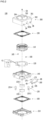
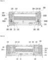
- FIG. 1 is a perspective view of a lens driving device 100 according to an embodiment
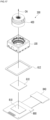
- FIG. 2 is a separated perspective view of the lens driving device 100 in FIG. 1
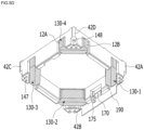
- FIG. 3 is a perspective view of the lens driving device 100 without the cover member 300 in FIG. 1 .
- the lens driving device 100 may include a cover member 300, a bobbin 110, a coil 120, a sensing magnet 180, a magnet 130, and a housing 140.
- the lens driving device 100 may further include a position sensor 170.
- the lens driving device 100 may include an elastic member coupled to the bobbin 110 and the housing 140.
- the elastic member may further include at least one of the upper elastic member 150 and the lower elastic member 160.
- the lens driving device 100 may further include a circuit board 190.
- the lens driving device 100 may further include a balancing member 185.
- the lens driving device 100 may further include a base 210.
- Bobbin 110 may be disposed within cover member 300.
- the bobbin 110 may be disposed on the base 210 and spaced apart from the base 210. Also, for example, the bobbin 110 may be disposed inside the housing 140.
- the bobbin 110 may be moved in the optical axis OA direction or in the first direction (eg, Z-axis direction) by an electromagnetic interaction between the coil 120 and the magnet 130.
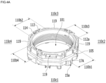
- FIG. 4A is a perspective view of the bobbin 110 in FIG. 1
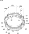
- FIG. 4B is a view illustrating the bobbin 110, the coil 120, the sensing magnet 180, and the balancing member 185 in FIG. 1 .
- a lens or lens barrel may be mounted on the bobbin 110.
- the bobbin 110 may have an opening 101 for mounting a lens or lens barrel.
- the opening 101 of the bobbin 110 may be a through hole, and its shape may be circular, oval, or polygonal, but is not limited thereto.
- a thread for coupling to a lens or lens barrel may be formed on an inner peripheral surface of the bobbin 110. In another embodiment, no thread is formed on the inner peripheral surface of the bobbin 110, and the bobbin 110 may be coupled to the lens or lens barrel using an adhesive.
- the bobbin 110 may include a plurality of sides, outer surfaces, or side surfaces.
- the bobbin 110 nay include side portions 110b1 to 110b4 corresponding to the side portions 141-1 to 141-4 of the housing 140 and corner portions 110c1 to 110c4 corresponding to corner portions 142-1 to 142- of the housing 140.
- Each of the corner portions 110c1 to 110c4 of the bobbin 110 may be disposed between two adjacent side portions 110b1 to 110b4 of the bobbin 110.
- a first length in the horizontal direction or a cross direction of each of the side portions 110b to 110b4 of the bobbin 110 may be different from a second length in the horizontal direction or the cross direction of each of the corner portions 110c1 to 110c4.
- the first length may be larger than the second length.
- the first length may be equal to the second length.
- the bobbin 110 may include a first coupling portion 113 coupled to the upper elastic member 150 and a second coupling portion 117 coupled to the lower elastic member 160.
- first coupling portion 113 may be disposed on a upper portion, an upper surface, or an upper end of the bobbin 110, and may be coupled to or fixed to the first inner frame 151 of the upper elastic member 150.
- the second coupling portion 117 may be disposed on a lower portion, a lower surface, or a lower end of the bobbin 110 and may be coupled to or fixed to the second inner frame 161 of the lower elastic member 160.
- Each of the first and second coupling portions 113 and 117 may have a protrusion shape, but in another embodiment, each of the first and second coupling portions may have a groove or flat shape.
- the bobbin 110 may include a first escape part 112a for avoiding or escaping spatial interference with the first connection portion 153 and a second escape part 112b for avoiding or escaping spatial interference with the second connection portion 163.
- the first escape part 112a may be formed in an area of an upper surface of the bobbin 110 that corresponds to or overlaps the first connection portion 153 in the optical axis direction, and may be recessed from the upper surface of the bobbin 110.
- the second escape part 112b may be formed in an area of a lower surface of the bobbin 110 that corresponds to or overlaps the second connection portion 163 in the optical axis direction, and may be recessed from the lower surface of the bobbin 110.
- each of the first and second escape parts 113 and 117 may have a groove shape.
- first and second escape parts 112a and 112b When the bobbin 110 moves in the first direction, by the first and second escape parts 112a and 112b, spatial interference between the first and second connection portions 153 and 163 and the bobbin 110 can be removed, and as a result, the first connection portion 153 and the second connection portion 163 can be easily elastically deformed.
- the bobbin 110 may include a seating portion 105 on which the coil 120 is disposed or seated.
- the seating portion 105 may be formed on the side surface or the outer surface of the bobbin 110.
- the seating portion 105 may have a groove shape.
- the coil 120 may be disposed or seated in the seating portion 105 of the bobbin 110.
- the coil 120 may be directly wound or wound around the seating portion 105 of the bobbin 110 so at to rotate clockwise or counterclockwise with respect to the optical axis OA.
- the bobbin 110 may not be provided with a seating part for seating the coil, and the coil may be directly wound or fixed to the outer surface of the bobbin 110 without a groove.
- the bobbin 110 may include a protrusion 17A and 17B protruding from the outer surface thereof.
- the protrusions 17A and 17B may be disposed on at least one of the side portions 110b1 to 110b4 of the bobbin 110.
- the first protrusion 17A may be disposed on the first side portion 110b1 of the side portions 110b1 to 110b4 of the bobbin 110
- the second protrusion 17B may be disposed on the second side portion 110b2 of the side portions 110b1 to 110b4 of the bobbin 110.
- the second side portion 110b2 may be located on the opposite side of the first side portion 110b1 with respect to the optical axis.
- the protrusions 17A and 17B may protrude in a direction parallel to a straight line which is perpendicular to the optical axis and passes through the optical axis.
- the protrusions 17A and 17B of the bobbin 110 may correspond to or face the grooves 22A and 22B of the housing 140. At least a portion of the protrusions 17A and 17B of the bobbin 110 may be inserted into or disposed within the grooves 22A and 22B of the housing 140, and may suppress or prevent the bobbin 110 from rotating over a certain range around the optical axis.
- the bobbin 110 may include a first groove 15a for disposing or seating the sensing magnet 180.
- the first groove 15a may be formed on the outer surface of one side portion of the bobbin 110.
- the first groove 15a may include an opening that exposes or opens at least a portion of the sensing magnet 180. At this time, the opening may be formed in at least one of the upper surface, a lower side, and the side surface of the bobbin 110.
- the bobbin 110 may include a second groove 15b for disposing or seating the balancing member 185.
- the second groove 15b may be formed on the outer surface of the side portion of the bobbin 110 that faces the side portion of the bobbin 110 where the first groove 15a is formed.
- first groove 15a may be formed at the first protrusion 17A of the bobbin 110
- second groove 15b may be formed at the second protrusion 17B of the bobbin 110.
- a guide portion 114 may be formed on the upper surface of the bobbin 110 to guide the installation position of the upper elastic member 150.
- the guide portion 114 of the bobbin 110 may protrude from the upper surface of the bobbin 110 to guide a path along which a portion of the inner frame of the upper elastic member 150 passes.
- At least one recess may be formed on the upper surface of the bobbin 110 and correspond to, face, or overlap at least one protrusion 303 of the cover member 300 in the optical axis direction.
- at least one groove 119 may be recessed from the upper surface of the bobbin 110.
- At least a portion of the protrusion 303 of the cover member 300 may be disposed in the groove 119 of the bobbin 110.
- the groove 119 of the bobbin 110 may function as an upper stopper together with the protrusion 303 of the cover member 300.
- the protrusion 303 and a bottom of the groove 119 of the bobbin 110 may be spaced apart.
- the bobbin 110 moves in the optical axis direction, for example, in an upward direction and the bottom of the groove 119 contacts the protrusion 303, so the bobbin 110 cannot move beyond the predetermined range.
- the bobbin 110 may include a stopper 116.
- the stopper 116 may protrude downward from the lower surface of the bobbin 110.
- the stopper 116 of the bobbin 110 may serve to prevent the lower surface of the bobbin 110 except the stopper 116 from directly colliding with the base 210.
- the bobbin 110 may include a protruding portion 115 for contacting the damper DA connected to the second connection portion 163 of the lower elastic member 160, which will be described later.
- the protruding portion 115 may protrude from the lower surface of the bobbin 110.
- the protruding portion 115 is for contact with the damper DA and can be expressed as a guide part or a protrusion instead.
- a groove may be formed in the protruding portion 115, and at least a portion of the damper DA may be disposed in the groove of the protruding portion 115, and may be in contact with or attached to the groove of the protruding portion 115.
- the coil 120 may be disposed on or coupled to bobbin 110.
- the coil 120 may be disposed on the outer surface of the bobbin 110.
- the coil 120 may be disposed in or wound on the seating portion 105 of the bobbin 110.
- the coil 120 may be disposed on the bobbin 110 to have a closed loop shape, for example, a ring shape.
- the coil 120 may have a ring shape wound clockwise or counterclockwise about the optical axis, and may be wound or disposed on the outer surface of the bobbin 110.
- the coil 120 may be implemented in the form of a coil ring wound or arranged in a clockwise or counterclockwise direction about an axis perpendicular to the optical axis, and the number of coil rings may be the same as the number of magnets 130. However, it is not limited to this.
- the coil 120 may be a driving coil that interacts electromagnetically with the magnet 130.
- a driving signal (eg, driving current or voltage) may be applied to the coil 120 to generate electromagnetic force by interaction with the magnet 130.
- the driving signal applied to the coil 120 may be a direct current signal, but is not limited thereto, and may be an alternating current signal or include a direct current signal and an alternating current signal.
- the AF moving unit may move in a first direction, for example, upward (+Z-axis direction) or downward (-Z-axis direction), by electromagnetic force resulting from the interaction between the coil 120 and the magnet 130.
- the strength or/and polarity e.g., direction in which current flows
- the strength or/and direction of electromagnetic force due to the interaction between the coil 120 and the magnet 130 can be controlled, and the movement of the AF moving unit in the first direction can be controlled, and thus an auto-focusing function can be performed.
- the AF moving unit may be unidirectionally driven or bidirectionally driven by electromagnetic force resulting from the interaction between the coil 120 and the magnet 130.
- unidirectional driving refers to moving the AF moving unit in one direction, for example, in the upward direction (e.g., upward direction (+Z-axis direction)) based on the initial position of the AF moving unit
- bidirectional driving refers to moving the AF moving unit in both directions (e.g., upward or downward) based on the initial position of the AF moving unit.
- the initial position of the bobbin 110 may be an initial position of the AF moving unit (eg, the bobbin) in a state where power or a driving signal is not applied to the coil 120.
- the initial position of the bobbin 110 may be a position where the AF moving unit is located as the result of the upper elastic member 150 and the lower elastic member 160 being elastically deformed due only to the weight of the AF moving unit.
- the initial position of the bobbin 110 may be the position at which the AF moving unit is placed when gravity acts in a direction from the bobbin 110 to the base 210, or, when gravity acts in a direction from the base 210 to the bobbin 110.
- the AF moving unit may be the bobbin 110 elastically supported by the upper elastic member 150 and the lower elastic member 160.
- the AF moving unit may further include components that are mounted on the bobbin 110 and move together with the bobbin 110.
- the AF moving unit may include the bobbin 110, the coil 120, the sensing magnet 180, and the balancing member 185, and may also include a lens or lens barrel when they are mounted.
- the coil 120 may be conductively connected to at least one of the upper elastic member 150 or the lower elastic member 160. Additionally, the coil 120 may be conductively connected to the circuit board 190 through at least one of the upper elastic member 150 or the lower elastic member 160. For example, by solder or conductive adhesive, the coil 120 may be coupled to or conductively connected to two of the upper springs of the upper elastic member 150, or to two of the lower springs of the lower elastic member.
- the coil 120 disposed on the bobbin 110 in the initial position may correspond to, face, or overlap the magnet 130 in a direction parallel to a straight line perpendicular to the optical axis and passing through the optical axis.
- the sensing magnet 180 may serve to provide a magnetic field for detection by the position sensor 170.
- the magnet 130 may be expressed as a "first magnet”
- the sensing magnet 180 may be expressed as a "second magnet”.
- the balancing member 185 can prevent the bobbin 110 from being tilted by the sensing magnet 180 during AF operation by balancing its weight with the sensing magnet 180, thereby the reliability of the AF operation can be ensured.
- the balancing member 185 may be a magnetic material.
- the balancing member 185 may be a magnetic metal member or a magnet.
- the balancing member 185 may be a non-magnetic material.
- the balancing member 185 may include non-magnetic metal or injection material.
- the balancing member 185 is a magnetic material, the influence of the magnetic field of the sensing magnet 180 on the coil 120 can be offset, thereby the reliability of AF operation can be improved.
- the sensing magnet 180 may be disposed on or coupled to the bobbin 110.
- the sensing magnet 180 may be disposed in the first groove 15a of the bobbin 110, and may be disposed to correspond to, face, or overlap the position sensor 170 in a direction perpendicular to the optical axis and passing through the optical axis.
- the sensing magnet 180 may be positioned lower than the coil 120.
- the balancing member 185 may be positioned lower than the coil 120.
- an upper surface of the sensing magnet 180 may be positioned lower than the coil 120, and a lower surface of the balancing member 185 may be positioned lower than the coil 120.
- a portion of one surface of the sensing magnet 180 facing the position sensor 170 may be exposed from the opening of the first groove 15a. In another embodiment, a portion of one surface of the sensing magnet 180 facing the position sensor 170 may not be exposed from the first groove 15a.
- the sensing magnet 180 may be a unipolar magnetized magnet including single N pole and single S pole.
- the sensing magnet 180 may be a bipolar magnetized magnet or a four-pole magnet including two N poles and two S poles.
- the sensing magnet 180 can move in the optical axis direction together with the bobbin 110. And the position sensor 170 can detect the magnetic field strength or magnetic force of the sensing magnet 180 which moves in the optical axis direction, and output an output signal according to the detected result.
- the magnetic field strength or magnetic force of the sensing magnet 180 detected by the position sensor 170 may be changed depending on a displacement of the bobbin 110 in the optical axis direction, and the position sensor 170 can output the output signal proportional to the strength of the detected magnetic field, and the displacement of the bobbin 110 in the optical axis direction can be detected using the output signal of the position sensor 170.
- the position sensor 170 may detect the position of the bobbin 110 or the position of the sensing magnet 180 in the optical axis direction.
- the balancing member 185 may have a weight to balance the weight of the sensing magnet 180.
- the balancing member 185 may have the same weight as the sensing magnet 180.
- the balancing member 185 may be alternatively expressed as "balancing magnet” or "third magnet.”
- the housing 140 may be disposed on base 210.
- the housing 140 may be disposed inside the cover member 300.
- the housing 140 can accommodate the bobbin 110 inside.
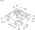
- FIG. 5A is a first perspective view of the housing 140
- FIG. 5B is a first perspective view of the housing 140, the magnet 130, the circuit board 190, the position sensor 170, and the capacitor 175.
- FIG. 5C is a second perspective view of the housing 140
- FIG. 5D is a second perspective view of the housing 140, the magnet 130, the circuit board 190, the position sensor 170, and the capacitor 175.
- the housing 140 supports the magnet 130 and accommodates the bobbin 110 inside so that the AF moving unit, for example, the bobbin 110 can move in the direction of the optical axis.
- the housing 140 may have an overall hollow column shape.
- the housing 140 may include an opening 401 to accommodate the bobbin.
- the opening 401 of the housing 140 may have a polygonal (eg, square or octagonal) or circular shape.
- the opening 401 of the housing 140 may be in the form of a through hole that penetrates the housing 140 in the optical axis direction.
- the housing 140 may include a plurality of side portions (eg, 141-1 to 141-4) and a plurality of corner portions (eg, 142-1 to 142-4).
- the housing 140 includes the first side portion 141-1 and the second side portion 141-2 which are opposite to each other with respect to the optical axis, and the third side portion 141-3 and the fourth side portion 141-4 which are disposed between the first and second side portions 141-1 and 141-2 and opposite to each other with respect to the optical axis.
- the housing 140 includes the first corner portion 142-1 located between the first side portion 141-1 and the fourth side portion 141-4, the second corner portion 142-2 located between the first and third side portions 141-1 and 141-3, the third corner portion 142-3 located between the second and third side portion 141-2 and 141-3, and the fourth corner portion 142-4 located between the second and fourth side portion 141-2 and 141-4.
- Each of the first to fourth side portions 141-1 to 141-4 of the housing 140 may correspond to, face or overlap any one of the first to fourth side plates 302A to 320D of the cover member 300.
- each of the first to fourth side portions 141-1 to 141-4 of the housing 140 is parallel to a corresponding one of the first to fourth side plates 302A to 320D of the cover member 300.
- Each of the first to fourth side portions 141-1 to 141-4 of the housing 140 may correspond to one of the first to fourth side portions 110b1 to 110b4 of the bobbin 110, and each of the first to fourth corner portions 142-1 to 142-4 of the housing 140 may correspond to one of the first to fourth corner portions 110c1 to 110c4 of the bobbin 110.
- the corner portions 142-1 to 142-4 of the housing 140 may include post parts 42A to 42D, respectively.
- Each of the post parts 42A to 42D may include an corner of the housing 140 corresponding to an corner of the side plate 302 of the cover member 300.
- the housing 140 may include a seating portion 141a (or a receiving portion) for mounting or disposing the magnet 130.
- the seating portion 141a for disposing or seating the magnet 130 may be formed in at least one of the corner portions 142-1 to 142-4 of the housing 140.
- the seating portion 141a may be provided at a lower portion or a lower end of at least one of the corner portions 142-1 to 142-4 of the housing 140.
- the seating portion 141a of the housing 140 may be formed as a recess having a shape corresponding to that of the magnet 130, for example, a concave groove.
- the seating portion of the housing 140 may be in the form of a hole or through hole.
- the housing 140 may include openings 33A, 33B, 33C, and 33D to expose at least a portion of the magnet 130.
- the housing 140 may include a first opening 33A for exposing or opening a first portion 12A of the magnet 130.
- the housing 140 may include a second opening 33B for exposing or opening a second portion 12B of the magnet 130.
- the housing 140 may include a third opening 33C for opening or exposing at least a portion of a first side surface 11A of the magnet 130.
- the housing 140 may include a fourth opening 33D exposing at least a portion of a lower surface 10B of the magnet 130.
- first opening 33A may be located on one side of the post parts 42A to 42D of the housing 140
- second opening 33B may be located on another side of the post parts 42A to 42D of the housing 140
- the post parts 42A to 42D may be located between the first opening 33A and the second opening 33B of the housing 140.
- the housing 140 may include at least one of the first to fourth openings 33A to 33D.
- the seating portion 141a of the housing 140 may include the first opening 33A and the second opening 33B described above.
- the seating portion 141a may include at least one of the third and fourth openings 33C and 33D.
- the housing 140 may include a stopper 145.
- the stopper 143 may be formed at an upper portion, an upper surface, or an upper end of the housing 140.
- the stopper 143 may protrude from the upper surface 140A of the housing 140 toward an inner surface of the upper plate 301 of the cover member 300.
- the stopper 145 can prevent the upper portion or the upper surface 140A of the housing 140 from directly colliding with the inner surface of the upper plate 301 of the cover member 300 due to an external impact.
- the stopper 145 may be expressed as a "boss” or "protrusion” instead.
- the housing 140 may include a first coupling portion 143 coupled to the upper elastic member 150 and a second coupling portion 147 coupled to the lower elastic member 160.
- first coupling portion 143 may be formed at the upper portion, the upper surface, or the upper end of the housing 140
- second coupling portion 147 may be formed at the lower portion, the lower surface, or the lower end of the housing 140.
- Each of the first and second coupling portions 143 and 147 may have a protrusion shape, but in other embodiments, they may have a recess or a flat shape.
- first coupling portion 143 may be coupled to the first outer frame 152 of the upper elastic member 150
- second coupling portion 147 may be coupled to the second outer frame 162 of the lower elastic member 150.
- the first coupling portion 143 may be disposed on at least one of the side portions 141-1 to 141-4 and the corner portions 142-1 to 142-4 of the housing 140.
- the second coupling portion 147 may be disposed on at least one of the side portions 141-1 to 141-4 and the corner portions 142-1 to 142-4 of the housing 140.
- the housing 140 may include recess portions 22A and 22B that correspond to or face the protrusions 17A and 17B of the bobbin 110.
- the housing 140 includes a first recess portion 22A corresponding to or facing the first protrusion 17A of the bobbin 110 and a second recess portion corresponding to or facing the second protrusion 17B of the bobbin 110.
- first recess portion 22A may be disposed on an inner surface of the first side portion 141-1 of the housing 140, and the second recess portion 22B may be disposed on the second side portion 141-2 of the housing 140.
- the housing 140 may include a recess 148 that corresponds to, face, or overlaps the protrusion 216 of the base 210 in the optical axis direction.
- the recess 148 may also be expressed as a guide recess.
- the recess 148 may be formed at the lower portion, the lower surface, or the lower end of at least one of the corner portions 142-1 to 142-4 of the housing 140.
- the recess 148 may be formed at a lower portion, a lower surface, or a lower end of the post parts 42A to 42D of the housing 140.
- the recess 148 of the housing 140 and the protrusion 216 of the base 210 may be coupled to each other by an adhesive member, and the housing 140 may be coupled to the base 210.
- the housing 140 may include a recess 40 to avoid spatial interference with the first connection portion 153 of the upper elastic member 150.
- the recess 40 may be formed on the upper portion, the upper surface, or the upper end of the housing 140.
- the recess 40 may be recessed from the upper surface 140A of the housing 140 and may include a bottom surface 40A and a side wall 40B.
- the recess 40 may be formed at the upper surface 140A of the corner portions 142-1 to 142-4 of the housing 140.
- the housing 140 may include a hole 51 for injecting adhesive.
- the hole 51 may be a through hole that penetrates the housing 140.
- the hole 51 may be formed at the corner portions 142-1 to 142-4 of the housing 140.
- the hole 51 may be a through hole penetrating the corner portions 142-1 to 142-4 of the housing 140.
- the hole 51 may be connected or communicated with the seating groove 141a of the housing 140 and may expose at least a portion of the magnet 130 (for example, at least a portion of the upper surface of the magnet 130) .
- the hole 51 may have a dumbbell shape, but in other embodiments, it may have a circular or polygonal shape.
- the hole 51 may be formed in the bottom surface 40B of the recess 40 of the housing 140 and may penetrate the bottom surface 40B of the recess 40.
- the housing 140 may include a structure for being coupled to the circuit board 190, for example, a recess or a protrusion.
- the housing 140 may include a mounting groove (or groove) 21A for accommodating at least a portion of the circuit board 190.
- the mounting groove 21A may be formed on the first side portion 141-1 of the housing 140.
- the mounting groove 21A may be formed on the outer surface of the first side portion 141-1 of the housing 140.
- the circuit board 190 may be coupled to or fixed to the housing 140 by an adhesive.
- the circuit board 190 may be attached to the first side portion 141-1 (eg, the mounting groove 21A) of the housing 140 using an adhesive.
- the housing 140 may include an opening 23 (or an escape portion) to avoid spatial interference with the position sensor 170 and the capacitor 175 disposed or mounted on the circuit board 190.
- the opening 23 may be formed at the first side portion 141-1 of the housing 140.
- the opening 23 may be open to the inner and outer surfaces of the first side portion 141-1 of the housing 140.
- the opening 23 may be in the form of a hole penetrating the first side portion 141-1 of the housing 140.
- the opening 23 may be in the form of a recess.
- the magnet 130 may be disposed in the housing 140 or may be combined with the housing 140.
- the magnet 130 can generate electromagnetic force by an interaction with the coil 120, and may be a driving magnet that can move the bobbin 110 by the electromagnetic force.
- the magnet 130 may include a plurality of magnet units 130-1 to 130-4.
- each of the magnet units 130-1 to 130-4 may be disposed at or coupled to a corresponding one of the corner portions 142-1 to 142-4 of the housing 140.
- the magnet units may be disposed on the side portions 141-1 to 141-4 of the housing 140.
- each of the magnet units 130-1 to 130-4 is disposed in the seating portion 141a of a corresponding one of the first to fourth corner portions 141-2 to 142-4 of the housing 140.
- the magnet 130 may be disposed at a corner of the cover member 300.
- the magnet 130 may be disposed to correspond to, face, or overlap the corner of the side plate 302 of the cover member 300.
- the magnet 130 may be arranged so that at least a portion of the magnet 130 overlaps the corner of the cover member 300 in the diagonal direction.
- the magnet 130 may be arranged so that at least a portion of the magnet 130 overlaps the corner of the side plate 302 of the cover member 300 in the diagonal direction.
- the diagonal direction may be a direction perpendicular to the optical axis and from the corner of the cover member 300 toward the optical axis.
- each of the magnet units 130-1 to 130-4 may be disposed at one of the corresponding corners of the cover member 300.
- each of the magnet units 130-1 to 130-4 may be disposed adjacent to one of the corresponding corners of the side plate 302 of the cover member 300.
- each of the magnet units 130-1 to 130-4 may be disposed to correspond to, face, or overlap one of the side plates 302A to 302D of the cover member 300.
- the magnet 130 may have a polyhedral shape that is easy to be disposed or seated on the corner portions 142-1 to 142-4 of the housing 140.
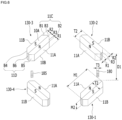
- FIG. 6 is a perspective view of the magnet units 130-1 to 130-4, the sensing magnet 180, and the balancing member 185.
- one magnet unit (eg, 130-3) may be equally applied or inferred to the remaining magnet units 130-1, 130-2, and 130-4.
- the first magnet unit, the second magnet unit, the third magnet unit, and the fourth magnet unit defined in FIG. 6 are examples, and in another embodiment, one of the four magnet units 130-1 to 130 in FIG. 6 may be "first magnet unit”, and another one of the four magnet units 130-1 to 130-4 may be “second magnet unit”, another one of the four magnet units 130-1 to 130-4 may be "third magnet unit,” and the remaining one of the four magnet units 130-1 to 130-4 may be "fourth magnet unit.”
- the magnet unit (e.g., 130-3) includes a first side surface 11A facing an outer side surface of the coil 120 or the bobbin 110, and a second side surface 11B located on opposite side of the first side surface 11A, a third side surface 11C connecting one end of the first side surface 11A and one end of the second side surface 11B, and a fourth side surface 11D connecting the other end of the first side surface 11A and the other end of the second side surface 11B.
- the magnet unit (e.g., 130-2) includes an upper surface 10A located on the first to fourth side surfaces 11 A to 11D and a lower surface 10B located below the first to fourth side surfaces 11A to 11D and located on the opposite side of the upper surface 10A.
- an area of the first side surface 11A of the magnet unit (eg, 130-3) may be larger than or equal to an area of the second side surface 11B.
- a cross direction length of the first side surface 11A of the magnet unit (eg, 130-3) may be greater than or equal to a cross direction length of the second side surface 11B.
- the magnet unit may include a first portion R1, and a cross direction length of the first portion R1 gradually increases in a direction from the first side surface 11A toward the second side surface 11B.
- the magnet unit may include a second portion R2, and a cross direction length of the second portion R2 decreases in the direction from the first side surface 11A toward the second side surface 11B.
- the first portion R1 may have one of the first polarity and the second polarity
- the second portion R2 may have the other polarity of the first polarity and the second polarity.
- the first polarity may be the N pole
- the second polarity may be the S pole.
- the magnet unit may include a third portion R3, and a cross direction length of the third portion R3 is constant in the direction from the first side surface 11A toward the second side surface 11B.
- the cross direction of the magnet unit may be parallel to a cross direction of the first side surface 11A of the magnet unit (eg, 130-2) .
- the third part R3 is a first region that is in contact with the first portion R1 and has the same polarity as the first portion R1, and a second region that is in contact with the second portion R2 and has the same polarity as the second portion R2.
- the first portion R1 may include the first side surface 11A
- the second portion R2 may include the second side surface 11B
- the third portion R2 may be disposed between the first portion R1 and the second portion R2.
- One side of the third portion R2 may be connected to the first portion R1, and the other side of the third portion R2 may be connected to the second portion R2.
- the magnet unit (eg, 130-3) may be left and right symmetrical with respect to a boundary surface between the N and S poles.
- the magnet unit (eg, 130-3) may be left and right asymmetric with respect to the boundary surface between the N and S poles.
- the third portion R2 may be omitted, and the first portion R1 may be connected to the second portion R2. In another embodiment, at least one of the first portion R1 and the third portion R3 may be omitted, and the remaining part may be implemented to include the N pole and the S pole.
- the third side surface 11C may include a first surface B1 connected to or in contact with the second side surface 11B and a second surface B2 connected to or in contact with the first side surface 11A. Additionally, the third side surface 11C may include a third surface B3 located between the first surface B1 and the second surface B2 and connecting the first surface B1 and the second surface B2.
- the fourth side 11D may include a fourth surface B4 connected to or in contact with the second side surface 11B, and a fifth surface B5 connected to or in contact with the first side surface 11A.
- the fourth side surface 11D may include a sixth surface B6 located between the fourth surface B4 and the fifth surface B5 and connecting the fourth surface B4 and the fifth surface B5.
- at least one of the third surface B3 and the sixth surface B6 may be omitted.
- the first portion R1 of the first magnet unit 130-1 and the first portion R1 of the second magnet unit 130-2 may face or overlap the sensing magnet 180 in a direction from the first corner portion 142-1 of the housing 140 toward the second corner portion 142-2 of the housing 140.
- the second surface B2 (or the fifth surface B5) of the first magnet unit 130-1 and the second surface B2 (or the fifth surface B5) of the second magnet unit 130-2 may face or overlap the sensing magnet 180 in the direction from the first corner portion 142-1 of the housing 140 toward the second corner portion 142-2 of the housing 140.
- the second surface B2 (or the fifth surface B5) of the third magnet unit 130-3 and the second surface B2 (or fifth surface B5) of the fourth magnet unit 130-4 may face or overlap the balancing member 185 in a direction from the third corner portion 142-3 of the housing 140 toward the second corner portion 142-4 of the housing 140.
- Each of the magnet units 130-1 to 130-4 may be composed of one body and may be a monopolar magnetized magnet including a single N pole and a single S pole.
- the first surface 11A of each of the magnet units 130-1 to 130-4 may be any one of S pole and N pole
- the second surface 11B of each of the magnet units 130-1 to 130-4 may be the other one of the S pole and the N pole.
- each of the magnet units 130-1 to 130-4 may be a bipolar magnetization magnet or a quadrupole magnet including two N poles and two S poles.
- each of the first to fourth magnet units 130-1 to 130-4 includes a first magnet portion, a second magnet, and a partition wall disposed between the first magnet portion and the second magnet portion.
- the first magnet portion may include an N pole, an S pole, and a first boundary surface between the N pole and the S pole.
- the first boundary surface is a portion having substantially no magnetism and may include a section having little polarity, and may be a portion that is naturally generated to form a magnet consisting of one N pole and one S pole.
- the second magnet portion may include an N pole, an S pole, and a second boundary surface between the N pole and the S pole.
- the second boundary surface is a portion having substantially no magnetism, and may include a section having little polarity, and may be a portion that is naturally generated to form a magnet consisting of one N pole and one S pole.
- the partition wall may be a portion that separates or isolates the first magnet portion and the second magnet portion from each other, and that has substantially no magnetism and may be a portion having little polarity.
- the partition wall may be a non-magnetic material, air, etc.
- the partition wall may be expressed as a "Neutral Zone" or "Neutral region”.
- the partition wall is a portion that is artificially formed when the first and second magnet units are magnetized, and a width of the partition wall may be larger than a width of each of the first and second boundary surfaces.
- the width of the partition wall may be a length of the partition wall in a direction from the first magnet portion to the second magnet portion.
- a planar shape of each of the magnet units 130-1 to 130-4 may be a polygonal shape, for example, a hexagon, a pentagon, a triangle, or a Rhombic shape.
- the magnet 130 includes four magnet units, but in another embodiment, the magnet may include two magnet units, and the two magnet units are arranged in two corner portions located on opposite sides of the housing 140.
- the circuit board 190 may be disposed on or coupled to the housing 140.
- the circuit board 190 may be disposed on one side portion 141-1 of the housing 140.
- the circuit board 190 may be disposed on or coupled to the mounting groove 21A of the housing 140.
- the circuit board 190 may be disposed between one side portion 141-1 of the housing 140 and one side plate 302A of the cover member 300.
- the circuit board 190 may be disposed on the outer surface of the first side portion 141-1 of the housing 140.
- circuit board 190 may be disposed between the first corner portion 142-1 and the second corner portion 142-2 of the housing 140.
- the circuit board 190 may be conductively connected to the coil 120.
- the circuit board 190 may be conductively connected to the position sensor 170.
- the circuit board 190 may be conductively connected to at least one of the upper elastic member 150 or the lower elastic member 160.
- the circuit board 190 may be conductively connected to the first and second lower springs 160A and 160B.
- the circuit board 190 includes a first pad 6A conductively connected to the first lower spring 160A by conductive adhesive or solder and a second pad 6B conductively connected to the second lower spring 160B by conductive adhesive or solder.
- the circuit board 190 may include a third pad 6C conductively connected to the cover member 300 by conductive adhesive or solder.
- the circuit board 190 may include a first surface that faces the inner surface of the side plate 302 of the cover member 300 and a second surface that is opposite to the first surface of the circuit board 190.
- the first to third pads 6A to 6C may be disposed on the first surface of the circuit board 190.
- the first and second pads 6A and 6B may be disposed on the second surface of the circuit board 190.
- the side plate 302 of the cover member 300 has a first groove 3A (or first opening) for exposing the first pad 6A of the circuit board 190 and a second groove 3B (or a second opening) for exposing the second pad 6B of the circuit board 190.
- each of the first and second grooves 3A and 3B may be formed at a lower surface of the side plate 302 of the cover member 300.
- the circuit board 190 may include a terminal portion 195 including at least one terminal P1 to P7.
- at least one terminal P1 to P7 may be disposed on the first side of the circuit board 190.
- the circuit board 190 may include a plurality of terminals P1 to P7.
- the circuit board 190 may include first to fourth terminals P1 to P4 conductively connected to the position sensor 170.
- the circuit board 190 may include a fifth terminal P5 conductively connected to the third pad 6C. Also, for example, the circuit board 190 may include at least one test terminal P6, P7 (or an additional terminal).
- the terminals P1 to P7 of the circuit board 190 may be positioned lower than the side plate 302 of the cover member 300.
- the terminals P1 to P7 of the circuit board 190 may be exposed from the side plate 302 of the cover member 300.
- the circuit board 190 includes seven terminals P1 to P7 for electrical connection with the outside (e.g., terminals of the circuit board 800 of the camera device 200), but is not limited thereto and may include four terminals or more than eight terminals in other embodiments.
- the circuit board 190 may include a circuit pattern or wirings for conductively connecting the position sensor 170 and the terminals P1 to P4. Additionally, the circuit board 190 may include circuit patterns or wirings for conductively connecting the third pad 6C and the fifth terminal. Additionally, the circuit board 190 may include circuit patterns or wiring for conductively connecting the position sensor 170 and the first and second pads 6A and 6B.
- the circuit board 190 may be a printed circuit board or a flexible printed circuit board.
- the position sensor 170 may be disposed on housing 140.
- the position sensor 170 may be disposed or mounted on the circuit board 190.
- the position sensor 170 may be conductively connected to the circuit board 190.
- the position sensor 170 may be mounted or disposed on the second side of the circuit board 190, and at least a portion of the position sensor 170 is disposed within the opening 23 of the housing 140 formed on the first side portion 141-1 of the housing 140.
- the position sensor 170 may not overlap the coil 120 parallel to a straight line perpendicular to the optical axis and passing through the optical axis. In another embodiment, at the initial position of the bobbin 110, the position sensor 170 may partially overlap the coil 120 in a direction parallel to a straight line perpendicular to the optical axis and passing through the optical axis.
- the position sensor 170 can detect the strength of the magnetic field of the sensing magnet 180 mounted on the bobbin 110 according to the movement of the bobbin 110, and output an output signal (e.g., output voltage) according to the detected result.
- the position sensor 170 may detect the position (or displacement) of the bobbin 110 or the position (or displacement) of the sensing magnet 180 in the optical axis direction.
- the position sensor 170 may be a driver including a Hall sensor. In another embodiment, the position sensor may be implemented as the hall sensor alone.
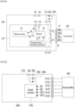
- Fig. 7A is a block diagram illustrating an embodiment of the position sensor 170, the circuit board 190, and the capacitor 175.
- the positional relationship between the position sensor 170 and the capacitor 175 is an example shown for ease of explanation.
- the position sensor 170 in FIG. 7A may include a Hall sensor 61 and a driver 62.
- the Hall sensor 61 may be made of silicon-based material, and the output VH of the Hall sensor 61 may increase as the ambient temperature increases.
- the ambient temperature may be the temperature of the lens moving apparatus, for example, the temperature of the circuit board 190, the temperature of the Hall sensor 61, or the temperature of the driver 62.
- the Hall sensor 61 may be made of GaAs, and the output VH of the Hall sensor 61 may have a slope of about -0.06%/°C with respect to the ambient temperature.
- the position sensor 170 may further include a temperature sensing element 63 capable of detecting the ambient temperature.
- the temperature sensing element 63 may output a temperature sensing signal Ts corresponding to the result of detection of the ambient temperature of the position sensor 170 to the driver 62.
- the Hall sensor 61 of the position sensor 170 may generate the output VH corresponding to the result of detection of the intensity of the magnetic force of the sensing magnet 180.
- VH may be in the form of voltage, but is not limited thereto, and may be in the form of current in other embodiments.
- VH may be a digital signal, but is not limited thereto, and may also be an analog signal.
- the driver 62 may output a driving signal dV for driving the Hall sensor 61 and a driving signal Id1 for driving the coil 120.
- the driver 62 may receive a clock signal SCL, a data signal SDA, and power signals VDD and GND from the controller 830 or 780.
- the driver 62 may generate the driving signal dV for driving the Hall sensor 61 and the driving signal Id1 for driving the coil 120 using the clock signal SCL and the data signal SDA.
- the driving signal dV may be an analog signal or a digital signal and may be in the form of a current or voltage.
- the driving signal Id1 may be in the form of current or voltage.
- the position sensor 170 includes first and second terminals (or pads) 9-1, 9-2 for receiving power or power signals VDD, GND, and third and fourth terminals (or pads) 9-3 and 9-4 for transmitting and receiving the clock signal SCL and the data signal SDA.
- the position sensor 170 may include two terminals, which are fifth and sixth terminals (or pads) 9-5 and 9-6 for providing the driving signal Id1 to the coil 120.
- the circuit board 190 includes a first terminal P1 conductively connected to the first terminal 9-1 of the position sensor 170, a second terminal P2 conductively connected to the second terminal 9-2 of the position sensor 170, a third terminal P3 conductively connected to the third terminal 9-3 of the position sensor 170, and a fourth terminal P4 conductively connected to the fourth terminal 9-4 of the position sensor 170.
- the first pad 6A of the circuit board 190 may be conductively connected to the fifth terminal 9-5 of the position sensor 170
- the second pad 6B may be conductively connected to the sixth terminal 9-6 of the position sensor 170
- the fifth and sixth terminals 9-5 and 9-6 of the position sensor 170 may be conductively connected to the first and second lower springs 160A and 160B.
- the fifth and sixth terminals 9-5 and 9-6 of the position sensor 170 may be conductively connected to the coil 120.
- the driver 62 can receive the output VH of the Hall sensor 61, and can transmit the clock signal SCL and the data signal SDA related the output VH of the Hall sensor 61 by data communication using a protocol, for example, I2C communication to the controller 830 and 780 through the terminals P3 and P4 of the circuit board 190.
- a protocol for example, I2C communication
- the driver 62 can receive the temperature detection signal Ts measured by the temperature sensing element 63, and transmit the temperature detection signal Ts to the controller 830 and 780 by data communication using a protocol, for example, I2C communication through the terminals P3 and P4 of the circuit board 190.
- the controller 830 and 780 may perform temperature compensation for the output VH of the Hall sensor 61 based on the change in ambient temperature measured by the temperature sensing element 63 of the position sensor 170.
- the capacitor 175 may be disposed on the housing 140.
- the capacitor 175 may be disposed on the first side portion 141-1 of the housing 140. At least a portion of the capacitor 175 may be disposed within the opening 23 of the housing 140.
- the capacitor 175 may be disposed or mounted on the circuit board 190.
- the capacitor 175 may be disposed on the second surface of the circuit board 190.
- the capacitor 175 may be in the form of a chip, and the capacitor 175 has a first terminal 195a conductively connected to one end of the capacitor 175 and a second terminal 195b conductively connected to the other end of the capacitor 175.
- the capacitor 175 may also be alternatively expressed as a "capacitive element" or a condenser.
- the capacitor 175 may be implemented to be included in the circuit board 190.
- the circuit board 190 may include a capacitor including a first conductive layer, a second conductive layer, and an insulating layer (eg, dielectric layer) disposed between the first conductive layer and the second conductive layer.
- the capacitor 175 may be conductively connected in parallel to the first and second terminals P1 and P2 of the circuit board 190 to provide power (or a driving signal) to the position sensor 170 from the outside.
- the capacitor 175 may be conductively connected in parallel to the first and second terminals 9-1 and 9-2 of the position sensor 170.
- one end (or first terminal 195a) of the capacitor 175 may be conductively connected to the first terminal P1 of the circuit board 190, and the other end (or second terminal 195b) of the capacitor 175 may be conductively connected to the second terminal P2 of the circuit board 190.
- first terminal 195a first terminal 195a
- second terminal 195b second terminal 195b
- the capacitor 175 is conductively connected in parallel to the first and second terminals P1 and P2 of the circuit board 190, so that High-frequency noise included in the power and the driving signal(e.g., current) supplied to the driver 62 from the outside can be removed.
- the capacitor 175 may serve as a smoothing circuit for removing ripple components or high-frequency components included in the power or the driving signal (eg, current) supplied to the driver 62 from the outside. Due to the capacitor 175, a stable and constant driving signal (or current) can be supplied to the driver 62 of the position sensor 170.
- Fig. 7B is a block diagram illustrating another embodiment of the position sensor 170a and the circuit board 190a according to another embodiment.
- the position sensor 170a can be implemented as a Hall sensor alone, and include two input terminals IN1 and IN2 for providing power or a driving signal and two output terminals OUT1 and OUT2 for outputting an output signal.
- the circuit board 190a may include first and second terminals 19-11 and 19-21 to which a power or a driving signal for driving the position sensor 170a is supplied.
- the first terminal 19-11 of the circuit board 190a may be conductively connected to the first input terminal IN1 of the position sensor 170a
- the second terminal 19-21 of the circuit board 190a may be conductively connected to the second input terminal IN2 of the position sensor 170a.
- circuit board 190 is conductively connected to a third terminal 19-31 conductively connected to the first output terminal OUT1 of the position sensor 170a and a fourth terminal (19-41) conductively connected to the second output terminal OUT2 of the position sensor 170a.
- the circuit board 190a includes fifth and sixth terminals 19-51 and 19-61 to which power or a driving signal for driving the coil 120 is supplied from an external device (e.g., the controller 830).
- the fifth terminal 19-51 of the circuit board 190a may be conductively connected to the first pad 6A of the circuit board 190a
- the sixth terminal 19-61 of the circuit board 190a may be conductively connected to the second pad 6B of the circuit board 190a.
- the fifth and sixth terminals 19-51 and 19-61 of the circuit board 190a may be conductively connected to the coil 120 through the lower springs 160A and 160B.
- the capacitor 175 may be conductively connected in parallel to the two input terminals IN1 and IN2 of the position sensor 170a.
- the capacitor 175 is conductively connected to the fifth and sixth terminals 19-51 and 19-61 of the circuit board 190, which are conductively connected in parallel to the input terminals IN1 and IN2 of the position sensor 170a.
- the sensing magnet may be disposed on the housing, and the position sensor may be disposed on the bobbin 110. Additionally, in another embodiment, the circuit board 190 may be disposed on the bobbin 110.
- FIG. 8A is a plan view of the upper elastic member 150
- FIG. 8B is a plan view of the lower elastic member 160
- FIG. 9 is a perspective view of the circuit board 190, the position sensor 170, the capacitor 175, the first and second lower springs 160A and 160B and the base 210
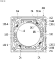
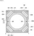
- FIG. 10 is a bottom view of the lens driving device 100 without the base 210
- FIG. 11 is a cross-sectional view of the lens driving device taken along line AB in FIG. 3
- FIG. 12 is a cross-sectional view of the lens driving device 100 taken along line CD in FIG. 3
- FIG. 13 is a cross-sectional view of the lens driving device 100 taken along line EF in FIG. 3 .
- the upper elastic member 150 may be coupled to the bobbin 110 and the housing 140.
- the lower elastic member 150 may be coupled to the bobbin 110 and the housing 140.
- at least one of the upper elastic member 150 and the lower elastic member 160 may support the bobbin 110 with respect to the housing 140.
- the upper elastic member 150 may be coupled to an upper portion, an upper surface, or an upper end of the bobbin 110 and an upper portion, an upper surface, or an upper end of the housing 140
- the lower elastic member 160 may be coupled to a lower portion, a lower surface, or a lower end of the bobbin 110 and a lower portion, a lower surface, or a lower end of the housing 140.
- the upper elastic member 150 or the lower elastic member 160 may be divided or separated into two or more pieces.
- the lower elastic member 160 may include a first lower spring 160A and a second lower spring 160B that are spaced apart from each other.
- the upper elastic member 150 and the lower elastic member 160 may be implemented as leaf springs, but are not limited thereto, and may also be implemented as coil springs, suspension wires, etc.
- the upper elastic member 150 includes a single upper spring that is not separated from each other, but is not limited thereto.
- the upper elastic member may include a plurality of upper springs, and the plurality of upper springs may be conductively connected to the coil 120.
- the upper elastic member 150 includes a first inner frame 151 coupled to the upper portion, the upper surface, or the upper end of the bobbin 110, a first outer frame 152 coupled to the upper portion, the upper surface, or the upper end of the housing 140, and a first connection portion 153 connecting the first inner frame 151 and the first outer frame 152.
- first inner frame can be expressed as “inner portion”
- outer frame can be expressed as “outer portion”.
- the upper elastic member 150 may include four first connection portions 153, and at least a portion of each of the four first connection portions is disposed at a corresponding one of the first to fourth corner portions 142-1 to 142-4 of the housing 140.
- the first inner frame 151 of the upper elastic member 150 may include a groove 151a(or a hole) coupled to the first coupling portion 113 of the bobbin 110, and the first outer frame 152 may include a hole 152a(or a groove) coupled to the first coupling portion 144 of the housing 140.
- An escape groove 154 for avoiding spatial interference with a stopper 143 of the housing 140 may be provided at the corner portion of the first outer frame 152 of the upper elastic member 150.
- the first and second lower springs 160A and 160B may be coupled to the bobbin 110.
- the first and second lower springs 160A and 160B may be coupled with the bobbin 110 and the housing 140.
- the first and second lower springs 160A and 160B may be disposed between the bobbin 110 (or housing 140) and the base 210.
- At least one of the first and second lower springs 160A and 160B may include a second inner frame 161 coupled to the lower portion, the lower surface, or the lower end of the bobbin 110, a second outer frame 162 coupled to the lower portion, the lower surface, or the lower end of the housing 140, and a second connection portion 163 connecting the second inner frame 161 and the second outer frame 162.
- an escape groove 166 may be formed in the second outer frame 162 to avoid spatial interference with the protrusion 216 of the base 210.
- one end of the coil 120 is coupled or conductively connected to a portion 7A (or first bonding portion) of the second inner frame 161-1 of the first lower spring 160A by soldering or a conductive member.
- the other end of the coil 120 may be coupled or conductively connected to a portion 7B (second bonding portion) of the second inner frame 162 of the second lower spring 160B by soldering or a conductive member.
- an insertion groove for guiding the coil 120 may be formed at the bonding portions 7A and 7B of the first and second lower springs 160A and 160B.
- one end or an end portion of the second outer frame 162 of the first lower spring 160A may be conductively connected to the first pad 6A of the circuit board 190 by using conductive adhesive or solder.
- one end or an end portion of the second outer frame 162 of the second lower spring 160B may be conductively connected to the second pad 6B of the circuit board 190 by using conductive adhesive or solder.
- the driving signal may be provided to the coil 120 through the first and second pads 6A and 6B of the circuit board 190 and the first and second lower springs 160A and 160B.
- Each of the first connection portion 153 of the upper elastic member 150 and the second connection portion 163 of the lower elastic member 160 is bent or curved (or curved) at least once to form a pattern of a certain shape.
- the bobbin 110 may be elastically or flexibly supported in an upward and/or downward motion in the first direction through a change in position and slight deformation of the first and second connection portions 153 and 163.
- each of the upper elastic member 50 and the lower elastic member 160 may be formed of a conductive material.
- the lens driving device 100 may further include a damper (not shown) disposed between the upper elastic member 150 and the housing 140.
- the second connection portion 163 of the lower springs 160A and 160B may include a protrusion 163A.
- the protrusion 163A may be spaced apart from the second inner frame 161.
- the protrusion 163A may be spaced apart from the second outer frame 162.
- the protrusion 163A may be spaced apart from the first end of the second connection portion 163 connected to the second inner frame 161.
- the protrusion 163A may be spaced apart from the second end of the second connection portion 163 connected to the second outer frame 162.
- the protrusion 163A may include a hole.
- the lens driving device 100 may include a damper DA disposed between the bobbin 110 and the protrusion 163A of the second connection portion 163.
- the damper DA may be coupled or attached to the protrusion 163A of the second connection portion 163 and the bobbin 110.
- the damper DA may be disposed between the protrusion 163A of the second connection portion 163 and the protrusion 115 of the bobbin 110, and contact or attach each of the protrusion 163A of the second connection portion 163 and the protrusion 115 of the bobbin 110.
- a damper (not shown) may be further disposed between the inner surface of the housing 140 and the outer surface of the bobbin 110.
- the base 210 may include an opening 210A corresponding to the opening 101 of the bobbin 110 and/or the opening 401 of the housing 140.
- the base 210 may have a shape that matches or corresponds to the cover member 300, for example, a square shape.
- the base 210 may include a step 212 on which adhesive can be applied when the base is fixed to the cover member 300 by adhesive.
- the step 212 may be formed at the outer side surface of the base 210.
- the step 212 may be positioned at a lower portion or a lower end of the outer side surface of the base 210.
- the step 212 may guide the side plate 302 of the cover member 300, which is coupled to the upper side of the base, and may face the lower end of the side plate 302 of the cover member 300.
- An adhesive member or/and a sealing member may be disposed or applied between the lower end of the side plate 302 of the cover member 300 and the step 211 of the base 210, and the lower end of the side plate 302 of the cover member 300 and the step 212 of the base 210 may be coupled to each other.
- At least one groove 217 for injecting an adhesive member or a silicone member may be formed in the step 212 of the base 210.
- the base 210 may be disposed under the bobbin 110 or the housing 140.
- the base 210 may be disposed under the lower elastic member 160.
- the base 210 may include the protrusion 216 protruding from the upper surface thereof.
- the protrusion 216 may be disposed at a corner of the upper surface of the base 210.
- the protrusion 216 may have a polygonal post shape, but is not limited thereto.
- the protrusion 216 may also be expressed as a post instead.
- the protrusion 216 may be inserted into the groove 148 of the housing 140 and may be coupled to the groove 148 of the housing 140 by an adhesive member (not shown) such as epoxy or silicon.
- the base 210 may include a stopper 23 protruding from the upper surface of the base 210.
- the stopper 23 of the base 210 may be arranged to correspond to, face, or overlap the stopper 116 of the bobbin 110 in the optical axis direction.
- a portion of the circuit board 190 may be disposed on the outer side surface of the base 210.
- the terminal portion 195 may be formed on a part of the circuit board 190 disposed on the outer side surface of the base 210.
- a seating groove (not shown) for seating or disposing a portion of the circuit board 190 may be formed on the outer side surface of the base 210, and the portion of the circuit board 190 is disposed in the seating groove of the base 210.
- the base 210 has grooves 22 to prevent spatial interference with the bonding portions 62a and 62b of the first and second lower springs 160a and 160b disposed on the base 210 and to facilitate soldering.
- the grooves 22 of the base 210 may be recessed from the upper surface of the base 210 and may be connected to the seating groove 210a, but is not limited thereto, and the grooves may not be connected to the seating groove.
- the cover member 300 may form an accommodation space together with the base 210, and the housing 140, the bobbin 110, and the components disposed on the housing 140 and the bobbin 110 are accommodated in the accommodation space.
- the cover member 300 may have a box shape having an open lower portion and include the upper plate 301 and the side plate 302.
- the lower end of the side plate 302 of the cover member 300 may be coupled to the base 210.
- the shape of the upper plate 302 of the cover member 300 may be circular or polygonal, for example, square or octagonal.
- the upper plate 302 of the cover member 300 may include an opening 303 for exposing a lens (not shown) to external light.
- the opening 303 may be a through hole that penetrates the upper plate 302 of the cover member 300 in the optical axis direction.
- the cover member 300 may include a protrusion 304 that protrudes downward from the upper plate 301.
- the cover member 300 may include a plurality of protrusions that correspond to or face the magnet units 130-1 to 130-4.
- the protrusion 304 may be formed adjacent to the opening 303 of the cover member 300.
- the protrusion 304 may be disposed inside the corresponding magnet unit.
- the protrusion 304 among the protrusion 304 and the corresponding magnet unit may be positioned closer to the optical axis.
- at least a portion of the protrusion 302 may overlap the corresponding magnet unit in a direction parallel to a straight line perpendicular to the optical axis and passing through the optical axis.
- the protrusion of the cover member 300 and the corresponding magnet unit may not overlap with each other.
- the side plate 302 of the cover member 300 may include first to fourth side plates 302A to 302D corresponding to the first to fourth side portions 141-1 to 141-4 of the housing 140.
- FIG. 14A is a flipped perspective view of the cover member 300, the housing 140, and the magnet 130
- FIG. 14B is a plan view of the cover member 300, the housing 140, and the magnet 130 of FIG. 14A
- FIG. 15A is a perspective view of the cover member 300, the magnet 130, the sensing magnet 180, and the balancing member 185
- FIG. 15B shows a positional relationship between the cover member 300 and the first and second magnet units 130-1, 130-2, and the sensing magnet 180.
- the arrangement relationship between the first magnet unit 130-1 and the side plates 302A and 302D of the cover member 300 may be applied or inferred to the arrangement between the second to fourth magnet units 130-2 to 130-4 and the side plates 302A to 302D of the cover member 300.
- the magnet 130 may be disposed between the posts 42A to 42D of the housing 140 and the protrusion 304 of the cover member 300.
- the posts 42A to 42D of the housing 140 may be disposed between the corners CA1 to CA4 of the cover member 300 and the magnet units 130-1 to 130-4.
- the corners CA1 to CA4 of the cover member 300 may be a portion where two neighboring side plates of the cover member 300 meet.
- the magnet units 130-1 to 130-4 may be disposed inside the posts 42A to 42D of the housing 140.
- the positions of the magnet units 130-1 to 130-4 and the positions of the posts 42A to 42D of the housing 140 may be reversed.
- the post of the housing 140 may be disposed inside the magnet unit.
- the first surface 11A of the magnet 130 may face the protrusion 304 of the cover member 300, and the second face 11B of the magnet 13 may face the posts 42A to 42D.
- At least a portion of the magnet 130 may be open or exposed from the outer side surface of the housing 140, and at least the exposed portion of the magnet 130 may be in contact with the inner surface of the side plate 302 of the cover member 300.
- first portion 12A of the magnet 130 may be open or exposed from the first opening 33A of the housing 140
- second portion 12B of the magnet 130 may be open or exposed from the second opening 33A of the housing 140.
- At least a portion of the first portion 12A of the magnet 130 may be in contact with the inner surface of the side plate 302 of the cover member 300, and at least a portion of the second portion 12B of the magnet 130 may be in contact with the inner surface of the side plate 302 of the cover member 300.
- first portion 12A of the magnet unit may be in contact with the inner surface of the first side plate 302A of the cover member 300 adjacent to the first portion 12A
- at least a portion of the second portion 12B of the magnet unit may be in contact with the inner surface of the fourth side plate 302D of the cover member 300 adjacent to the second portion 12B.
- the first to fourth magnet units 130-1 to 130-4 may be in contact with the inner surfaces of the first to fourth side plates 302A to 302D of the cover member 300.
- Two contact regions can be formed between one magnet unit and the two side plates of the cover member 300, and in FIG. 14b , eight contact regions S1 to S8 may be formed between the magnet 130 and the side plates 302 of the cover member 300.
- one end of the second portion R2 (see FIG. 6 ) of the magnet unit (e.g., 130-1) exposed from the first opening 33A of the housing 140 may be in contact with the first side plate 302A (e.g., inner surface of the side plate 302A) of the cover member 300, and the other end of the second portion R2 (see FIG. 6 ) of the magnet unit (e.g., 130-1) exposed from the second opening 33B of the housing 140 may be in contact with the fourth side plate 302D (e.g., inner surface of the fourth side plate 302D) of the cover member 300.
- the first side plate 302A e.g., inner surface of the side plate 302A
- the fourth side plate 302D e.g., inner surface of the fourth side plate 302D
- the third side surface 11C of the magnet unit (e.g., 130-1) shown in FIG. 6 may be in contact with the first side plate 302A of the cover member 300, and at least a portion of the fourth side surface 11D of the magnet (e.g., 130-1) may be in contact with the fourth side plate 302D of the cover member 300.
- the first surface B1 of the third side 11C of the magnet unit (e.g., 130-1) may be in contact with the inner surface of the first side plate 302A of the cover member 300
- the fourth surface B4 of the fourth side 11D of the magnet unit (e.g., 130-1) may be in contact with the inner surface of the fourth side plate 302D of the cover member 300.
- the polarity of the portion of the magnet 130 that is in contact with the side plate 302 of the cover member 300 may be any one of N pole and S pole.
- portions of the magnet units 130-1 to 130-4 that contact the side plates 302A to 302D of the cover member 300 may have the same polarity. Since the cover member 300 has a yoke function, in case that portions of the magnet units with different polarities (e.g., 130-1) contact the side plate 302 of the cover member 300, the magnetic fields may be offset each other so that the yoke function may be reduced, and as a result, the effect of increasing electromagnetic force between the coil 120 and the magnet units 130-1 to 130-4 may be reduced.
- the cover member 300 has a yoke function, in case that portions of the magnet units with different polarities (e.g., 130-1) contact the side plate 302 of the cover member 300, the magnetic fields may be offset each other so that the yoke function may be reduced, and as a result, the effect of increasing electromagnetic force between the coil 120 and the magnet units 130-1 to 130-4 may be reduced.
- a portion of the magnet unit (e.g., 130-1) in contact with the side plate 302 of the cover member 300 may include both the N pole and the S pole.
- the magnet units 130-1 to 130-4 may be spaced apart from the side plate 302 of the cover member 300.
- the cover member 300 may include a first opening 305A that corresponds to, faces, or overlaps the sensing magnet 180.
- the cover member 300 may include a second opening 305B that corresponds to, faces, or overlaps the balancing member 185.
- the first opening 305A and the second opening 305B may be formed in the side plate 302 of the cover member 300.
- the first opening 305A may be formed at the first side plate 302A of the cover member 300 corresponding to or facing the first side 141-1 of the housing 140
- the second opening 305B may be formed at the second side plate 302B of the cover member 305 corresponding to or facing the second side 141-2 of the housing 140.
- the first opening 305A may be formed in a part of the first side plate 302A of the cover member 300 corresponding to, facing, or overlapping a part of the first side portion 141-1 of the housing 140 between the first magnet unit 130-1 and the second magnet unit 130-2.
- the second opening 305B is formed in a part of the second side plate 302B of the cover member 300 corresponding to, facing, or overlapping a part of the second side portion 142-2 of the housing 140 between the third magnet unit 130-3 and the fourth magnet unit 130-4.
- the first opening 305A may be open to the inner and outer surfaces of the first side plate 302A of the cover member 300.
- the first opening 305A may be open to the lower surface of the first side plate 302A of the cover member 300.
- the first opening 305A may extend to the lower surface of the first side plate 302A of the cover member 300.
- the first opening 305A may be spaced apart from an edge where the first side plate 302A and the upper plate 301 of the cover member 300 meet.
- the first opening 305A may extend to an edge where the first side plate 302A and the upper plate 301 of the cover member 300 meet.
- the first opening 305A may be in the form of a through hole, hollow, or window penetrating the first side plate 302A of the cover member 300.
- the second opening 305B may be open to the inner and outer surfaces of the second side plate 302B of the cover member 300.
- the second opening 305B may be open to the lower surface of the second side plate 302B of the cover member 300.
- the second opening 305B may extend to the lower surface of the second side plate 302B of the cover member 300.
- the second opening 305B may be spaced apart from an edge where the second side plate 302B and the upper plate 301 of the cover member 300 meet.
- the second opening 305B may extend to an edge where the second side plate 302B and the upper plate 301 of the cover member 300 meet.
- the second opening 305B may be in the form of a through hole, hollow, or window penetrating the second side plate 302B of the cover member 300.
- the shape of the first opening 305A and the shape of the second opening 305B may be the same. In another embodiment, the shape of the first opening 305A and the shape of the second opening 305B may be different.
- the second opening 305B may be located on the opposite side of the first opening 305A with respect to the optical axis.
- the first opening 305A and the second opening 305B may be arranged to be symmetrical to each other with respect to the optical axis.
- first opening 305A and the second opening 305B may be overlapped with each other in a direction perpendicular to the optical axis OA and toward the second side plate 302B from the first side plate 302A.
- an area of the first opening 305A may be larger than an area of the side surface (or the front surface) of the sensing magnet 180 when viewed from the front of the first side plate 302A of the cover member 300.
- a cross direction length L1 of the first side plate 302A of the cover member 300 is equal to a cross direction length L2 of the third side plate 302A of the cover member 300.
- L1 and L2 may be different.
- the cross direction length L1 of the first side plate 302A of the cover member 300 may be 12 [mm] to 18 [mm].
- L1 may be 14 [mm] to 16 [mm].
- L1 may be 14.5 [mm] to 15.5 [mm].
- a lengthwise length M1 of the first side plate 302A of the cover member 300 may be 4 [mm] to 7 [mm]. Or, for example, M1 may be 4.5 [mm] to 6 [mm]. Or, for example, M1 may be 4.5 [mm] to 5.5 [mm].
- a thickness (T1, see FIG. 14A ) of the cover member 300 may be 0.2 [mm] to 0.6 [mm]. Or, for example, the thickness T1 of the cover member 300 may be 0.3 [mm] to 0.5 [mm]. Or, for example, the thickness T1 of the cover member 300 may be 0.4 [mm] to 0.45 mm.
- L1 may be a length of the first side plate 302A in a direction parallel to the first side plate 302A
- L2 may be a length in a direction from the upper end of the first side plate 302A to the lower end of the first side plate 302A
- T1 may be a length or a thickness from the outer side surface of the first side plate 302A to the inner side surface of the first side plate 302A.
- the description of the cross direction length and lengthwise length of the first side plate 402A may be applied to or inferred to the cross direction length and lengthwise length of each of the second to fourth side plates 402B to 42D of the cover member 300. Additionally, the description of the thickness T1 of the cover member 300 may be applied or inferred to the thickness of each of the first to fourth side plates 302A to 302D and the thickness of the protrusion 304 of the cover member 300.
- a cross direction length H1 of the magnet unit may be 2.4 [mm] to 8.4 [mm].
- H1 may be 4.4 [mm] to 6.4 [mm].
- H1 may be 4.8 [mm] to 5.6 [mm] .
- the lengthwise length M2 of the magnet unit may be 1.2 [mm] to 3.2 [mm].
- M2 may be 1.4 [mm] to 2.8 [mm].
- M2 may be 1.8 [mm] to 2.4 [mm] .
- the thickness T2 of the magnet unit may be 1 [mm] to 3 [mm]. Or, for example, T2 may be 1.4 [mm] to 2.6 [mm]. Or, for example, in order to increase the electromagnetic force by the interaction with the coil 120, the thickness T2 of the magnet unit (e.g., 130-1) may be 1.8 [mm] to 2.2 [mm] .
- H1 may be applied or inferred to the cross direction length of other magnet units (e.g., 130-2 to 130-4), and M2 may be applied to the lengthwise length of other magnet units (e.g., 130-2 to 130-4), and T2 may be applied or inferred to the thickness of other magnet units (e.g., 130-2 to 130-4).
- H1 may be the maximum length of the magnet unit (e.g., 130-1) in a direction parallel to the first surface (11A) (or second surface (11B)) of the magnet unit (e.g., 130-1).
- M2 may be the length of the magnet unit (e.g., 130-1) in a direction from the upper surface of the magnet unit (e.g., 130-1) toward the lower surface of the magnet unit (e.g., 130-1).
- T2 is the length of the magnet unit (e.g., 130-1) in a direction from the first surface 11A of the magnet unit (e.g., 130-1) toward the second surface 11B or a distance between the surface 11A and the second surface 11B.
- the thickness K1 of the coil 120 may be 0.3 [mm] to 1 [mm].
- the thickness K1 of the coil 120 may be 0.45 to 0.67.
- the thickness K1 of the coil 120 may be 0.5 to 0.6.
- the camera device mounted on the vehicle since the weight of the lens module mounted on the lens driving device of the camera device mounted on the vehicle is greater than the weight of the lens module mounted on a mobile device, for example, a mobile phone, when compared to the camera device on the mobile device, the camera device mounted on the vehicle requires a larger electromagnetic force to move the bobbin in the optical axis direction.
- the embodiment may include a coil 120 having a thickness greater than a thickness of the AF coil of the lens driving device of the camera device mounted on the mobile device in order to secure greater electromagnetic force.
- the cross direction length H2 of the sensing magnet 180 may be 0.3 [mm] to 1.1 [mm].
- H2 may be 0.5 [mm] to 0.9 [mm].
- H2 may be 0.65 [mm] to 0.75 [mm]
- the thickness T3 of the sensing magnet 180 may be 0.2 [mm] to 0.6 [mm].
- T3 may be 0.3 [mm] to 0.5 [mm].
- T3 may be 0.35 [mm] to 0.45 [mm] .
- H2 may be applied or inferred to the cross direction length of the balancing member 185
- M3 may be applied or inferred to the lengthwise length of the balancing member 185
- T3 is applied or inferred to the thickness of the balancing member 185.
- the cross direction length L3 of the first opening 305A may be 1.5 [mm] to 3.5 [mm].
- L3 may be 2 [mm] to 3 [mm].
- L3 may be 2.4 [mm] to 2.8 [mm] .
- the lengthwise length L4 of the first opening 305A may be 1.8 [mm] to 3.8 [mm].
- L4 may be 2 [mm] to 2.8 [mm].
- L4 may be 2.2 [mm] to 2.6 [mm] .
- the separation distance D1 between the first magnet unit 130-1 and the second magnet unit 130-2 may be 3.5 [mm] to 8 [mm].
- D1 may be 4.5 [mm] to 6.5 [mm].
- D1 may be 5 [mm] to 6 [mm].
- D1 may be the distance from one end (e.g., B2 or B5) of the first magnet unit 130-1 to one end (e.g., B2 or B5) of the second magnet unit 130-2.
- the value D1/L3 obtained by dividing the separation distance D1 by the cross direction length L3 of the first opening 305A may be 1 to 5.3.
- the divided value D1/L3 is less than 1, the first opening 305A and the magnet units 130-1 and 130-2 may be overlapped with each other, so that the yoke function may be weakened, and the electromagnetic force between the magnet units 130-1 and 130-2 and the coil 120 may be reduced.
- the divided value D1/L3 is greater than 5.3, the area of the first opening 305A nay become too small and the magnetic field interference between the magnet units 130-1 and 130-2 and the sensing magnet 180 may not be suppressed.
- the divided value (D1/L3) may be 2 to 4.
- the value L1/L3 obtained by dividing the cross direction length L1 of the first side plate 302A by the cross direction length L3 of the first opening 305A may be 4.2 to 10. If the divided value L1/L3 is less than 4.5, the size of the first opening 305A becomes too large, and the yoke function of the first side plate 302A is weakened, and the electromagnetic force between the magnet units 130-1 and 130-2 and the coil 120 may be reduced. On the other hand, when the divided value L1/L3 is greater than 10, the size of the first opening 305A becomes too small to suppress the magnetic field interference between the magnet units 130-1 and 130-2 and the sensing magnet 180.
- the electromagnetic force between the magnet units 130-1 and 130-2 and the coil 120 is not reduced, and at the same time, the magnetic field interference between the magnet units 130-1 and 130-2 and the sensing magnet 180 is suppressed.
- the divided value L1/L3 may be 5 to 7.
- the value M1/L4 obtained by dividing the lengthwise length M1 of the first side plate 302A by the lengthwise length L4 of the first opening 305A may be 1.1 to 3.8. If the divided value M1/L4 is less than 1.1, the size of the first opening 305A becomes too large and the yoke function of the first side plate 302A is weakened so that the electromagnetic force between the magnet units 130-1 and 130-2 and the coil 20 may be reduced. On the other hand, when the divided value M1/L4 is greater than 3.8, the size of the first opening 305A becomes too small to suppress the magnetic field interference between the magnet units 130-1 and 130-2 and the sensing magnet 180.
- the electromagnetic force between the magnet units 130-1 and 130-2 and the coil 120 is not reduced, and at the same time, the magnetic field interference between the magnet units 130-1 and 130-2 and the sensing magnet 180 is suppressed.
- the divided value M1/L4 may be 1.5 to 2.5.
- the value L3/H2 obtained by dividing the cross direction length L3 of the first opening 305A by the cross direction length H2 of the sensing magnet 180 may be 1.4 to 11. If the divided value L3/H2 is less than 1.4, the size of the first opening 305A may become too small to suppress the magnetic field interference between the magnet units 130-1 and 130-2 and the sensing magnet 180. On the other hand, when the divided value L3/H2 is greater than 11, the size of the first opening 305A becomes too large and the yoke function of the first side plate 302A is weakened so that the electromagnetic force between the magnet units 130-1 and 130-2 and the coil 120 may be reduced.
- the divided value L3/H2 may be 3 to 5.
- the value L4/M3 obtained by dividing the lengthwise length L4 of the first opening 305A by the lengthwise length M3 of the sensing magnet 180 may be 1.125 to 4.75. If the divided value L4/M3 is less than 1.125, the size of the first opening 305A may become too small to suppress the magnetic field interference between the magnet units 130-1 and 130-2 and the sensing magnet 180. On the other hand, when the divided value L4/M3 exceeds 4.75, the size of the first opening 305A becomes too large and the yoke function of the first side plate 302A is weakened so that the electromagnetic force between the magnet units 130-1 and 130-2 and the coil 120 may be reduced.
- the divided value L4/M3 may be 1.5 to 2.5.
- the description of the relationship between the sensing magnet 180, the first opening 305A, the distance D1, the first side plate 302A, and the first and second magnet units 130-1 and 130-2 may be applied and inferred to the relationship between the balancing member 185, the second opening 302B, the distance between the second and fourth magnet units, the second side plate 302B, and the third and fourth magnet units 130-3 and 130-4.
- the cover member 300 may be formed of a magnetic material and is disposed adjacent to or in contact with the magnet units 130-1 to 130-4, thereby the magnetic field generated from the magnet units 130-1 to 130-4 may be well transmitted to the sensing magnet 180 and the balancing member 185 through the cover member 300, and the effect of magnetic field interference may increase.
- the degree of tilt of the AF moving unit with respect to the optical axis during AF operation may increase, thereby the reliability of auto focusing may be deteriorated.
- the electromagnetic force between the coil 120 and the magnet units 130-1 to 130-4 may be reduced due to the magnetic field interference between the magnet units 130-1 to 130-4 and the sensing magnet 180.
- the first opening 305A prevents the magnetic field generated from the magnet units 130-1 and 130-2 from influencing the magnetic field of the sensing magnet 180 through the first side plate 302A of the cover member 300.
- the magnetic field interference between the sensing magnet 180 and the magnet units 130-1 and 130-2 which are driving magnets can be reduced by the first opening 305A.
- AF driving reliability can be improved by suppressing tilt of the bobbin 110 during AF driving due to magnetic field interference.
- by suppressing magnetic field interference between the magnet units 130-1 to 130-4 and the sensing magnet 180 by the first opening it is possible to prevent the electromagnetic force between the coil 120 and the magnet units 130-1 to 130-4 due to magnetic field interference from being reduced.
- the first dotted line 28A shown in FIG. 16 may be an area of the first side plate 305A where the first opening 305A is formed, and as shown in the first dotted line 28A, the first opening 305A formed in the first side plate 302A of the cover member 300 prevents the magnetic field of the first magnet unit 130-1 and the magnetic field of the second magnet unit 130-2 from expanding toward the sensing magnet 180.
- no opening is formed at a region (second dotted line 28B) of another side plate (e.g., 302C) of the cover member 300 located between the second magnet unit 130-2 and the third magnet unit 130-3.
- another side plate e.g., 302C
- the magnetic field of the first magnet unit 130-1 and the magnetic field of the second magnet unit 130-2 can be extended to a central area of the third side plate 305C. That is, in the embodiment, the influence of the magnetic field of the first magnet unit 130-1 and the magnetic field of the second magnet unit 130-2 on the magnetic field of the sensing magnet 180 can be suppressed by the first opening 305A.
- the magnetic field of the third magnet unit 130-3 and the magnetic field of the fourth magnet unit 130-4 can be suppressed from extending to the balancing member 185 by the second opening 305B, and the influence of the magnetic field of the third magnet unit 130-3 and the magnetic field of the fourth magnet unit 130-4 on the magnetic field of the balancing member 185 made of magnetic material can be suppressed.
- the magnetic field interference between the sensing magnet 180, the balancing member 185, and the magnet units 130-1 to 130-4 can be reduced by the first opening 305A and the second opening 305B. Because of this, in the embodiment, tilt of the AF moving unit during AF driving due to magnetic field interference can be suppressed, and the reliability of AF driving can be improved, and AF driving force can be prevented from being reduced.
- the cross direction length L3 of the first opening 305A may be greater than the cross direction length H2 of the sensing magnet 180.
- the cross direction length of the first opening 305A may be equal to or smaller than the cross direction length of the sensing magnet 180.
- the lengthwise length L4 of the first opening 305A may be larger than the lengthwise length M3 of the sensing magnet 180.
- the lengthwise length of the first opening 305A may be equal to or smaller than the lengthwise length of the sensing magnet 180.
- the cross direction length L3 of the first opening 305A may be smaller than the cross direction length L1 of the first side plate 302A, and the lengthwise length L4 of the first opening 305A may be smaller than the lengthwise length M1 of the first side plate 302A.
- the influence of the magnetic field of the magnet units 130-1 and 130-2 on the sensing magnet 180 can be suppressed or blocked.
- the sensing magnet 180 When the first side plate 302A is viewed from the front, the sensing magnet 180 may be disposed inside the first opening 305A of the cover member 300. For example, when the first side plate 302A is viewed from the front, the upper surface of the sensing magnet 180 may be positioned lower than an upper end of the first opening 305A of the cover member 300. Additionally, when the first side plate 302A is viewed from the front, the sensing magnet 180 may overlap the first opening 305A of the cover member 300. For example, when the first side plate 302A is viewed from the front, the sensing magnet 180 may not overlap the first side plate 302A of the cover member 300. And by arranging the sensing magnet 180, in the embodiment the influence of the magnetic field of the magnet units 130-1 and 130-2 on the sensing magnet 180 can be suppressed or blocked.
- a part of the sensing magnet 180 may overlap the first opening 305A of the cover member 300, and another part of the sensing magnet 180 may overlap the first side plate 302A of the cover member 300.
- the first opening 305A may be located between the first magnet unit 130-1 and the third magnet unit 130-3.
- the upper surface of the sensing magnet 180 may be positioned lower than the upper surface of the magnet units 130-1 and 130-2.
- the upper surface of the sensing magnet 180 may be positioned higher than the upper surface of the magnet units 130-1 and 130-2 or may be located at the same height.
- the lower surface of the sensing magnet 180 may be positioned lower than the lower surfaces of the magnet units 130-1 and 130-2. In another embodiment, the lower surface of the sensing magnet 180 may be higher than the lower surface of the magnet units 130-1 and 130-2 or may be located at the same height.
- the separation distance D1 between the first magnet unit 130-1 and the second magnet unit 130-2 may be greater than the cross direction length L3 of the first opening 305A of the cover member 300. In another embodiment, the separation distance D1 between the first magnet unit 130-1 and the second magnet unit 130-2 is equal to the cross direction length L3 of the first opening 305A of the cover member 300.
- each of the first magnet unit 130-1 and the second magnet unit 130-2 may not overlap the first opening 305A.
- the side plate 302A of the cover member 300 can prevent the magnetic field of the first and second magnet units 130-1 and 130-2 from leaking and concentrate the magnetic field of the first and second magnet units 130-1 and 130-2 on the coil 120. As a result, the electromagnetic force between the coil 120 and the first and second magnet units 130-1 and 130-2 can be increased.
- the magnet units 130-1 to 130-4 may contact the inner surfaces of the side plates 302A to 203D of the cover member 300 and the magnetic fields of the magnet units 130-1 to 130-4 may be focused on the coil 120 through the side plates 302A to 203D of the cover member 300. For this reason, in the embodiment, the electromagnetic force between the magnet units 130-1 to 130-4 and the coil 120 can be improved.
- the lens driving device 100 may include a first sealing member (not shown) (or a first adhesive) disposed in the first opening 305A of the cover member 300, and the first opening 305A may be sealed or closed by the first sealing member.
- the lens driving device may include a second sealing member (or a second adhesive) disposed in the second opening 305B of the cover member 300, and the second opening 305B may be sealed or closed by the second sealing member.
- a second sealing member or a second adhesive
- the lens driving device may be used in various fields, such as those of a camera device or an optical device.
- the lens driving device 100 may be included in the optical device configured to form an image of an object in a space using reflection, refraction, absorption, interference, diffraction, etc., which are characteristics of light, to increase the visual power of the eyes, to record or reproduce an image formed by a lens, to perform optical measurement, or to propagate or transfer an image.
- the optical device may include a smartphone or a mobile terminal including the camera.
- FIG. 17 is a separated perspective view of a camera device 200 according to an embodiment.
- the camera device 200 may include a lens module 400, the lens driving device 100, an adhesive member 612, a filter 610, a circuit board (800), an image sensor 810 and a connector 840.
- the lens module 400 may include a lens and/or a lens barrel and be mounted on the bobbin 110 of the lens driving device 100.
- the lens module may include one lens or more than one lenses and a lens barrel accommodating the lens.
- the configuration of the lens module is not limited to the lens barrel, and any holder structure that can support one or more lenses may be available for the lens barrel.
- the lens module is coupled to the lens driving device 100 and can move together with the lens driving device 100.
- the lens module 400 may be screw-coupled with the lens driving device 100 as an example.
- the lens module 400 may be coupled to the lens driving device 100 using an adhesive (not shown). Meanwhile, light passing through the lens module 400 may pass through the filter 610 and be irradiated to the image sensor 810.
- the adhesive member 612 may couple or adhere the base 210 of the lens driving device 100 to the circuit board 800.
- the adhesive member 612 may be epoxy, a thermo-hardening adhesive, or an ultraviolet-hardening adhesive.
- the filter 610 may serve to prevent a specific-frequency-band component of light passing through the lens barrel 400 from being incident on the image sensor 810.
- the filter 610 may be an infrared cutoff filter; however, the disclosure is not limited thereto. In this case, the filter 610 may be disposed parallel to the x-y plane.
- the filter 610 may be disposed below the base 210 of the lens driving device 100.
- the base 210 may include a seating portion (not shown) formed at a lower surface of the base 210 for seating the filter 610.
- a sensor base (not shown) for seating or disposing the filter 610 may be provided separately from the base 210.
- the circuit board 800 may be disposed under the lens driving device 100, and the image sensor 810 may be mounted on the circuit board 800.
- the image sensor 810 may receive an image included in light incident through the lens driving device 100 and convert the received image into an electrical signal.
- the circuit board 800 may include terminals for electrical connection to at least one of the terminals P1 to P7 of the circuit board 190 of the lens driving device 100 using solder or conductive adhesive.
- the image sensor 810 may be positioned so that the optical axis of the image sensor 810 coincides with that of the lens module 400. Through this, the image sensor can acquire light passing through the lens module 400.
- the image sensor 810 can output the irradiated light as an image.
- the image sensor 810 may be a charge coupled device (CCD), a metal oxide semiconductor (MOS), a CPD, or a CID.
- CCD charge coupled device
- MOS metal oxide semiconductor
- CPD CPD
- CID CID
- the type of image sensor is not limited to this.
- the filter 610 and the image sensor 810 may be arranged to be spaced apart from each other in the first direction.
- the connector 840 is conductively connected to the circuit board 800 and may have a port for electrical connection to an external device.
- FIG. 18a is a perspective view of the optical device 200A according to an embodiment
- FIG. 18b is a perspective view of the optical device 200X according to another embodiment
- FIG. 19 is a configuration diagram of the optical device 200A shown in FIG. 18A and FIG. 18B .
- the camera device 200 according to the embodiment of FIG. 18A may be a front camera in which the lens module 400 is arranged to face a front surface of the body 850
- the camera device 200 according to the embodiment of FIG. 18B may be a rear camera arranged to face the rear surface of the body 850 of the optical device 200A
- An optical device according in another embodiment may include both the front camera of FIG. 18A and the rear camera of FIG. 18B .
- the optical device 200A may include a body 850, a wireless communication unit 710, an A/V input unit 720, a sensing unit 740, an input/output unit 750, a memory unit 760, an interface unit 770, a controller 780, and a power supply unit 790.
- the body 850 shown in FIGs. 18A and 18B has a bar shape, however, the disclosure is not limited thereto.
- the body may have any of various structures, such as a slide type structure, a folder type structure, a swing type structure, and a swivel type structure, in which two or more sub-bodies are coupled so as to be movable relative to each other.
- the body 850 may include a case (casing, housing, cover, etc.) that defines the external appearance thereof.
- the body 850 may be divided into a front case 851 and a rear case 852.
- Various electronic parts of the terminal may be mounted in a space defined between the front case 851 and the rear case 852.
- the sensing unit 740 may sense the current state of the terminal 200A, 200X, such as the opening and closing state of the terminal 200A, 200X, the position of the terminal 200A, 200X, whether a user contacts the terminal, the orientation of the terminal 200A, 200X, and acceleration/deceleration of the terminal 200A, 200X, in order to generate a sensing signal for controlling the operation of the terminal 200A, 200X.
- the sensing unit may sense whether the slide phone is open or closed.
- the sensing unit senses whether electric power is supplied from the power supply unit 790 and whether the interface unit 770 is coupled to an external instrument.
- the input/output unit 750 is configured to generate input or output related to visual sensation, audible sensation, or tactile sensation.
- the input/output unit 750 may generate input data for controlling the operation of the terminal 200A, 200X, and may display information processed by the terminal 200A, 200X.
- the input/output unit 750 may include a keypad unit 730, a display module 751, a sound output module 752, and a touchscreen panel 753.
- the keypad unit 730 may generate input data through keypad input.
- the display module 751 may include a plurality of pixels, the color of which is changed according to an electrical signal.
- the display module 751 may include at least one of a liquid crystal display, a thin film transistor-liquid crystal display, an organic light-emitting diode, a flexible display, and a three-dimensional (3D) display.
- the sound output module 752 may output audio data received from the wireless communication unit 710 in a call signal reception mode, a telephone communication mode, a recording mode, a voice recognition mode, or a broadcast reception mode, or may output audio data stored in the memory unit 760.
- the touchscreen panel 753 may convert a change in capacitance due to a user's touch on a specific region of the touchscreen into an electrical input signal.
- the interface unit 770 functions as a path for connection between the terminal 200A, 200X and an external instrument.
- the interface unit 770 may receive data or electric power from the external instrument and transmit the received data or electric power to internal components of the terminal 200A, 200X, or may transfer data in the terminal 200A, 200X to the external instrument.
- the interface unit 770 may include a wired/wireless headset port, an external charger port, a wired/wireless data port, a memory card port, a port for connection with an apparatus having an identification module, an audio input/output (I/O) port, a video input/output (I/O) port, and an earphone port.
- the controller 780 may control the overall operation of the terminal 200A, 200X.
- the controller 780 may perform related control and processing for voice communication, data communication, and video communication.
- the controller 780 may have a multimedia module 781 for multimedia reproduction.
- the multimedia module 781 may be implemented in the controller 180 or may be implemented separately from the controller 780.
- the controller 780 may perform pattern recognition processing that is capable of recognizing writing input or drawing input performed on the touchscreen as text or an image, respectively.
- the power supply unit 790 may supply power required to operate the respective components upon receiving external power or internal power under the control of the controller 780.
- Embodiments may be used for a lens driving device, a camera device, and an optical device capable of improving electromagnetic force between a coil and a magnet unit and suppressing magnetic field interference between the sensing magnet and the magnet unit.
Landscapes
- Physics & Mathematics (AREA)
- General Physics & Mathematics (AREA)
- Optics & Photonics (AREA)
- Engineering & Computer Science (AREA)
- Multimedia (AREA)
- Signal Processing (AREA)
- Chemical & Material Sciences (AREA)
- Combustion & Propulsion (AREA)
- Electromagnetism (AREA)
- Power Engineering (AREA)
- Lens Barrels (AREA)
Applications Claiming Priority (2)
| Application Number | Priority Date | Filing Date | Title |
|---|---|---|---|
| KR1020220028711A KR20230131620A (ko) | 2022-03-07 | 2022-03-07 | 렌즈 구동 장치 및 이를 포함하는 카메라 모듈 및 광학 기기 |
| PCT/KR2023/003085 WO2023172024A1 (ko) | 2022-03-07 | 2023-03-07 | 렌즈 구동 장치 및 이를 포함하는 카메라 모듈 및 광학 기기 |
Publications (2)
| Publication Number | Publication Date |
|---|---|
| EP4492126A1 true EP4492126A1 (de) | 2025-01-15 |
| EP4492126A4 EP4492126A4 (de) | 2026-02-18 |
Family
ID=87935473
Family Applications (1)
| Application Number | Title | Priority Date | Filing Date |
|---|---|---|---|
| EP23767125.0A Pending EP4492126A4 (de) | 2022-03-07 | 2023-03-07 | Linsenansteuerungsvorrichtung und kameramodul sowie optische vorrichtung damit |
Country Status (5)
| Country | Link |
|---|---|
| US (1) | US20250172854A1 (de) |
| EP (1) | EP4492126A4 (de) |
| KR (1) | KR20230131620A (de) |
| CN (1) | CN118805126A (de) |
| WO (1) | WO2023172024A1 (de) |
Family Cites Families (7)
| Publication number | Priority date | Publication date | Assignee | Title |
|---|---|---|---|---|
| JP4693510B2 (ja) * | 2005-06-08 | 2011-06-01 | 三洋電機株式会社 | 対物レンズ駆動装置 |
| JP2014160196A (ja) * | 2013-02-20 | 2014-09-04 | Alps Electric Co Ltd | レンズ駆動装置 |
| KR102128839B1 (ko) | 2013-07-15 | 2020-07-01 | 엘지이노텍 주식회사 | 카메라 모듈 |
| KR102376814B1 (ko) * | 2014-03-17 | 2022-03-21 | 엘지이노텍 주식회사 | 렌즈 구동장치 및 이를 구비한 카메라 모듈 |
| JP6583601B2 (ja) * | 2014-08-06 | 2019-10-02 | ミツミ電機株式会社 | レンズホルダ駆動装置およびカメラ付き携帯端末 |
| KR102798057B1 (ko) * | 2018-08-17 | 2025-04-21 | 엘지이노텍 주식회사 | 렌즈 구동 장치, 및 이를 포함하는 카메라 모듈 및 광학 기기 |
| KR102759456B1 (ko) * | 2018-11-26 | 2025-01-24 | 엘지이노텍 주식회사 | 렌즈 구동 장치, 및 이를 포함하는 카메라 모듈 및 광학 기기 |
-
2022
- 2022-03-07 KR KR1020220028711A patent/KR20230131620A/ko active Pending
-
2023
- 2023-03-07 EP EP23767125.0A patent/EP4492126A4/de active Pending
- 2023-03-07 CN CN202380025971.9A patent/CN118805126A/zh active Pending
- 2023-03-07 US US18/843,383 patent/US20250172854A1/en active Pending
- 2023-03-07 WO PCT/KR2023/003085 patent/WO2023172024A1/ko not_active Ceased
Also Published As
| Publication number | Publication date |
|---|---|
| WO2023172024A1 (ko) | 2023-09-14 |
| EP4492126A4 (de) | 2026-02-18 |
| KR20230131620A (ko) | 2023-09-14 |
| US20250172854A1 (en) | 2025-05-29 |
| CN118805126A (zh) | 2024-10-18 |
Similar Documents
| Publication | Publication Date | Title |
|---|---|---|
| US12298531B2 (en) | Camera module | |
| EP3798724B1 (de) | Linsenansteuerungsvorrichtung und kameramodul sowie optische vorrichtung damit | |
| US12487432B2 (en) | Lens driving device, and camera module and optical device including same | |
| KR102864546B1 (ko) | 렌즈 구동 장치 및 이를 포함하는 카메라 모듈 및 광학 기기 | |
| CN116953880A (zh) | 透镜驱动装置及包括该驱动装置的摄像机模块和光学设备 | |
| CN113348660A (zh) | 透镜驱动设备及包括该透镜驱动设备的相机模块和光学设备 | |
| KR20250021506A (ko) | 렌즈 구동 장치, 이를 포함하는 카메라 모듈 및 광학 기기 | |
| KR102767041B1 (ko) | 렌즈 구동 장치, 이를 포함하는 카메라 모듈 및 광학 기기 | |
| KR102798057B1 (ko) | 렌즈 구동 장치, 및 이를 포함하는 카메라 모듈 및 광학 기기 | |
| KR102937627B1 (ko) | 렌즈 구동 장치, 이를 포함하는 카메라 모듈 및 광학 기기 | |
| KR20250053036A (ko) | 렌즈 구동 장치, 및 이를 포함하는 카메라 모듈 및 광학 기기 | |
| KR20250021350A (ko) | 렌즈 구동 장치 및 이를 포함하는 카메라 모듈 및 광학 기기 | |
| KR20250021357A (ko) | 렌즈 구동 장치, 이를 포함하는 카메라 모듈 및 광학 기기 | |
| EP4492126A1 (de) | Linsenansteuerungsvorrichtung und kameramodul sowie optische vorrichtung damit | |
| KR20200079056A (ko) | 렌즈 구동 장치 및 이를 포함하는 카메라 모듈 및 광학 기기 | |
| KR20220130082A (ko) | 렌즈 구동 장치, 및 이를 포함하는 카메라 모듈 및 광학 기기 | |
| US20250334771A1 (en) | Lens driving device, and camera module and optical device including same | |
| US12601956B2 (en) | Lens driving device, and camera device and optical instrument that include same | |
| US20260016735A1 (en) | Lens-driving device, camera device, and optical device | |
| KR20210007600A (ko) | 렌즈 구동 장치, 카메라 모듈 및 이를 포함하는 광학 기기 | |
| KR20260002401A (ko) | 렌즈 구동 장치, 및 이를 포함하는 카메라 모듈 및 광학 기기 | |
| KR20200113690A (ko) | 렌즈 구동 장치, 및 이를 포함하는 카메라 모듈 및 광학 기기 |
Legal Events
| Date | Code | Title | Description |
|---|---|---|---|
| STAA | Information on the status of an ep patent application or granted ep patent |
Free format text: STATUS: THE INTERNATIONAL PUBLICATION HAS BEEN MADE |
|
| PUAI | Public reference made under article 153(3) epc to a published international application that has entered the european phase |
Free format text: ORIGINAL CODE: 0009012 |
|
| STAA | Information on the status of an ep patent application or granted ep patent |
Free format text: STATUS: REQUEST FOR EXAMINATION WAS MADE |
|
| 17P | Request for examination filed |
Effective date: 20240926 |
|
| AK | Designated contracting states |
Kind code of ref document: A1 Designated state(s): AL AT BE BG CH CY CZ DE DK EE ES FI FR GB GR HR HU IE IS IT LI LT LU LV MC ME MK MT NL NO PL PT RO RS SE SI SK SM TR |
|
| DAV | Request for validation of the european patent (deleted) | ||
| DAX | Request for extension of the european patent (deleted) | ||
| REG | Reference to a national code |
Ref country code: DE Ref legal event code: R079 Free format text: PREVIOUS MAIN CLASS: G02B0027640000 Ipc: G03B0030000000 |
|
| A4 | Supplementary search report drawn up and despatched |
Effective date: 20260115 |
|
| RIC1 | Information provided on ipc code assigned before grant |
Ipc: G03B 30/00 20210101AFI20260109BHEP Ipc: G02B 27/64 20060101ALI20260109BHEP Ipc: G02B 7/02 20210101ALI20260109BHEP Ipc: G03B 13/36 20210101ALI20260109BHEP Ipc: H02K 41/035 20060101ALI20260109BHEP Ipc: H04N 23/51 20230101ALI20260109BHEP Ipc: H04N 23/57 20230101ALI20260109BHEP Ipc: G03B 3/10 20210101ALI20260109BHEP Ipc: G02B 7/08 20210101ALI20260109BHEP |