EP4492174A1 - Machine d'emballage et son procédé de fonctionnement - Google Patents
Machine d'emballage et son procédé de fonctionnement Download PDFInfo
- Publication number
- EP4492174A1 EP4492174A1 EP24181680.0A EP24181680A EP4492174A1 EP 4492174 A1 EP4492174 A1 EP 4492174A1 EP 24181680 A EP24181680 A EP 24181680A EP 4492174 A1 EP4492174 A1 EP 4492174A1
- Authority
- EP
- European Patent Office
- Prior art keywords
- manipulator
- packaging machine
- robot
- movement
- program
- Prior art date
- Legal status (The legal status is an assumption and is not a legal conclusion. Google has not performed a legal analysis and makes no representation as to the accuracy of the status listed.)
- Pending
Links
Images



Classifications
-
- G—PHYSICS
- G05—CONTROLLING; REGULATING
- G05B—CONTROL OR REGULATING SYSTEMS IN GENERAL; FUNCTIONAL ELEMENTS OF SUCH SYSTEMS; MONITORING OR TESTING ARRANGEMENTS FOR SUCH SYSTEMS OR ELEMENTS
- G05B19/00—Program-control systems
- G05B19/02—Program-control systems electric
- G05B19/42—Recording and playback systems, i.e. in which the program is recorded from a cycle of operations, e.g. the cycle of operations being manually controlled, after which this record is played back on the same machine
- G05B19/423—Teaching successive positions by walk-through, i.e. the tool head or end effector being grasped and guided directly, with or without servo-assistance, to follow a path
-
- B—PERFORMING OPERATIONS; TRANSPORTING
- B25—HAND TOOLS; PORTABLE POWER-DRIVEN TOOLS; MANIPULATORS
- B25J—MANIPULATORS; CHAMBERS PROVIDED WITH MANIPULATION DEVICES
- B25J11/00—Manipulators not otherwise provided for
-
- G—PHYSICS
- G05—CONTROLLING; REGULATING
- G05B—CONTROL OR REGULATING SYSTEMS IN GENERAL; FUNCTIONAL ELEMENTS OF SUCH SYSTEMS; MONITORING OR TESTING ARRANGEMENTS FOR SUCH SYSTEMS OR ELEMENTS
- G05B2219/00—Program-control systems
- G05B2219/30—Nc systems
- G05B2219/36—Nc in input of data, input key till input tape
- G05B2219/36433—Position assisted teaching
-
- G—PHYSICS
- G05—CONTROLLING; REGULATING
- G05B—CONTROL OR REGULATING SYSTEMS IN GENERAL; FUNCTIONAL ELEMENTS OF SUCH SYSTEMS; MONITORING OR TESTING ARRANGEMENTS FOR SUCH SYSTEMS OR ELEMENTS
- G05B2219/00—Program-control systems
- G05B2219/30—Nc systems
- G05B2219/40—Robotics, robotics mapping to robotics vision
- G05B2219/40202—Human robot coexistence
Definitions
- the present invention relates to a packaging machine with at least one program-controlled manipulator and to a method for programming movement routines of at least one program-controlled manipulator used within a packaging machine.
- the present invention finds its application in particular in the field of packaging machines, which, for example, form part of an integrated beverage filling and packaging system or can be arranged downstream of a beverage filling and handling system.
- packaging When processing, assembling, grouping and packaging items such as beverage containers, cans, etc., several different types of packaging are available, such as combining the items or containers into portable, relatively handy packaging units, which are often also referred to as containers or packaging units. Shrink film containers, strapping containers or cardboard containers are well known, although the container variants can also be combined with one another.
- the shrink film, paper or cardboard packaging for several articles or primary packaging is usually fed into the packaging machine as continuous material, whereby this continuous material is normally provided as roll material.
- the paper, cardboard or film material can be continuously unwound from such magazine rolls, divided into suitable length sections and, for example, placed around article or container groups using a wrapping module.
- the unwinding of the packaging material or shrink film from the roll used as a magazine is usually done mechanically and in a continuous process. Once such a roll has been unwound and the stock of If the packaging material is exhausted, the used roll must be replaced in order to be able to continue feeding the packaging material. While the automated change within the packaging machine from a used roll to a new roll with packaging material wound on it usually does not cause any difficulties due to the known roll positions in the respective magazine and can be carried out in a very short time, an automated exchange of new rolls normally requires more effort in order to avoid unwanted delays or interruptions in the process sequences.
- the DE 10 2021 100 035 A1 discloses a packaging system for packaging articles such as beverage containers, in which packaging material from at least one supply roll is made available to a packaging machine.
- the packaging material is used within the packaging machine to package groups of articles.
- Driverless transport vehicles are used in the packaging system disclosed here to supply the packaging machine with supply rolls and/or to transport used supply rolls away.
- handling devices designed as articulated arm robots can be provided, with which the supply rolls can be removed from the packaging machine and/or from the driverless transport vehicles or inserted into the packaging machine or placed on the transport vehicle.
- collaborative robots that are equipped and configured in such a way that robot-human interaction is largely safe.
- the use of such a collaborative robot is supported by the WO 2018 228 727 A1 proposed to assist in changing components within a container handling machine. It is proposed to operate the collaborative robot without a separating protective device, which enables the handling processes to be carried out by the robot to be directly controlled by a user located within the robot's movement area. In order to minimize the risk of collision with people in the vicinity of the collaborative robot, it is also proposed to equip the collaborative robot with a suitable safety system.
- collaborative robot makes it possible to react to changing pick-up or take-over positions for material supplies for consumables, e.g. in the form of film or paper rolls, that are to be picked up and inserted into a packaging machine.
- material supplies for consumables e.g. in the form of film or paper rolls
- collaborative robots requires increased monitoring and control effort in order to minimize risks for users who inevitably have to be within the action area of such a robot in order to support it in its positioning movements.
- the problem of increased personnel expenditure arises again, since the robot requires human support in order to be able to carry out more complicated movement routines and to avoid malfunctions.
- the primary aim of the invention can be considered to be to provide a packaging machine with a supply of consumables that is as error-tolerant as possible, with such processes being supported by robot technology.
- repeated feeding and/or exchange processes, in which further consumables are made available to the packaging machine, are to be made possible with reduced or minimized manual support.
- the invention proposes, in addition to a method explained below in different embodiments, a packaging machine with at least one program-controlled manipulator, to which manipulator is assigned a sensor system for detecting external influences acting on the manipulator, wherein the sensor and/or signal data detected by the sensor system are made available to a manipulator control as input variables for adapting the manipulation movements carried out by the manipulator to the external influences detected by the sensor system.
- a manipulator control can also be viewed in the broadest sense as a COBOT control, as will be explained in more detail below.
- the manipulator control can be operated in a programming mode which provides for a recording of at least those external influences detected by the sensor system which are based on manual influences by a user located within a movement area of the manipulator.
- program steps for creating new or modifying existing movement routines of the program-controlled manipulator can be derived from the manual influences on the manipulator which can be attributed to the user.
- the movement routines of the program-controlled manipulator or robot that are to be created and/or programmed in programming mode can be seen in particular in connection with the provision of consumables that are made available to the packaging machine regularly or as needed and that are used in the packaging machine.
- the consumables can be, for example, packaging material such as film, shrink film, paper material or similar, with which piece goods, article groups, container groups, etc. are wrapped or equipped in order to form packaging units or bundle units.
- the switch to COBOT mode can be initiated in particular by a sensor system provided for this purpose, so that, for example, a light grid or Ultrasonic sensors can detect when a person enters the movement area of the manipulator or robot.
- COBOT operation can be terminated either by sensory detection of a movement area free of people or by manual input.
- the sensors assigned to the manipulator or robot can be formed, for example, by optical sensors such as cameras with downstream image evaluation or, for example, by acoustic sensors.
- optical sensors such as cameras with downstream image evaluation
- acoustic sensors Preferably, however, it can be useful to design the sensors in such a way that the drive torques for the electric servomotors of the manipulator or robot are evaluated so that external influences can be deduced from this and/or that a user can be deduced from this who is within the movement area of the manipulator and influencing the manipulator.
- a first pass for programming the motion control of the manipulator or robot is completed. These processes can be repeated multiple times and in principle as often as desired. All movements that are carried out by the moving manipulator or robot sections in a user-guided manner are entered into an appropriately equipped memory area of the manipulator control so that they can be called up for future motion sequences.
- the manipulator or robot control can signal by optical and/or acoustic signal display or in another way that the processes are now known and can subsequently be carried out by the manipulator or robot in an automated and largely autonomous manner, i.e. without additional human guidance. If necessary, a confirmation or acknowledgement by the user may be useful before he or she leaves the safety area in the immediate vicinity of the manipulator or robot.
- the autonomous and/or automated process can be maintained at least until a new and previously unknown position appears for one of the start or target positions of the movable manipulator or robot arm, for example caused by the delivery of a new pallet with consumables whose set-down position differs from the set-down position of a pallet previously set down there.
- the user can start another programming cycle and teach the manipulator or robot in COBOT mode with new movement routines and program it in the manner described above.
- the main advantages of the appropriately equipped packaging machine and the method according to the invention explained below are that the user only has to accompany the loading processes for a comparatively short time, whereas the manipulator or robot can carry out most sections of the loading processes autonomously and/or automatically. There is no need to set up and program the moving manipulator or robot parts precisely, as this can be done in a simple and comparatively quick manner by programming the manipulator or robot in COBOT mode.
- the program-controlled manipulator can be formed in particular by a handling robot, which can be provided for different handling tasks in or on the packaging machine.
- a handling robot can, for example, comprise a movable swivel arm with arm sections that can move around several axes.
- Such handling robots often referred to as industrial robots, can, for example, be formed by so-called five-axis or six-axis articulated arm robots, on whose freely movable end section gripping elements or other manipulation elements can be arranged.
- the handling robot can also be formed by a parallel kinematics robot or the like.
- the invention proposes, in addition to the packaging machine described above, a method for programming movement routines of at least one program-controlled manipulator used within a packaging machine, with this manipulator being assigned a sensor system for detecting external influences on the manipulator.
- external influences used here can essentially mean manual influences by a user who is within a movement area of the manipulator. If a human user is within a movement area of the manipulator, the manipulation movements carried out by the manipulator are preferably adapted to the external influences detected by the sensor system, i.e. the moving parts of the manipulator can be controlled to a certain extent by the human user and the directions of movement can be specified by the user.
- a manipulator controlled in this way can be referred to as a collaborative manipulator or a collaborative robot, which is suitable and equipped to act either as a conventionally operated and purely program-controlled robot, if necessary using and additionally processing sensor signals to record its environment or in a robot-human interaction, i.e. to work as a not fully program-controlled robot or manipulator.
- programmed manipulator or "programmed robot” used here and in the context of the entire description can be understood in this context to mean handling devices whose movement sequences and movement routines are specified and controlled by a computer or by a computer-aided control unit, so that the movement sequences and movement routines are in particular essentially or completely program-controlled processes, which, however, does not exclude the additional use and processing of sensor signals of all kinds to modify and influence the movement sequences and/or movement routines.
- Such sensor signals can be used, for example, as the output signals of different detection devices that detect an area in front of or a movement area of the handling device and can, for example, detect unexpected objects or people in the movement area, so that after processing such sensor signals in the computer or the computer-aided control unit, unwanted collisions with the object or person can be prevented.
- collaborative manipulator or collaborative robot in the present context can be understood to mean handling devices whose movement sequences and movement routines are not completely specified and controlled by a computer or a computer-aided control unit, but in which robot-human interaction is also taken into account, so that such collaborative manipulators or collaborative robots are equipped with means and sensors that allow interaction with human users, so that they work together with them to complete a specific task and either carry out partial steps of such a process themselves or are involved in these processes in a supporting manner.
- the collaborative manipulator or collaborative robot can lift and position a component or object that the participating user can no longer handle alone, while the user himself is relieved of the heavy lifting tasks and essentially only maneuvers the component or object into the correct position, e.g. within a machine.
- collaborative manipulator or collaborative robot used here are to be understood as referring to the COBOTs known to those skilled in the art.
- the method according to the present invention now provides that at least defined sections of the manual influences specified by the user and detected by the sensors are recorded and processed for the creation of new or for the modification of existing movement routines of the program-controlled manipulator. All of these movement routines to be programmed for the program-controlled manipulator or robot can be seen in particular in connection with the provision of consumables that are used in the packaging machine.
- the consumables can be, for example, packaging material such as film, shrink film, paper material or similar.
- the at least one program-controlled manipulator used within the packaging machine can be used in two different operating modes, and it is possible to switch from one operating mode to the other and back again as required. If the available program routines are not sufficient for an upcoming handling task of the manipulator, for example because a new takeover position for picking up a heavy load that is to be transferred to a known position within the packaging machine is not yet known, the operating mode can be selected in which human-machine interaction is required in order to convey the new and previously unknown movement routine to the program control of the manipulator.
- This new movement routine which the manipulator executes by specifying and supporting manual influence, is recorded and used within the program control of the manipulator to create new movement routines or to modify existing ones.
- the manipulator can be a stationary or mobile articulated arm robot with arm sections that can move in multiple axes and a gripper arm arranged at the end, whereby the pivotally connected arm sections can be pivoted against each other using electric motor drives.
- the manipulator can also be a gantry robot, the tool head of which can also be mounted on an articulated arm suspended from above.
- Other variants are conceivable, such as so-called parallel kinematic robots or similar.
- a tool head of such a manipulator or robot can optionally have gripping arms with gripping jaws that can be moved towards each other or other dedicated gripping devices.
- gripping devices can be formed, for example, by a gripping mandrel with which heavy rolls with packaging material wound on them can be gripped by immersing the gripping mandrel vertically from above into a hollow cylindrical holder of a roll core and clamping it there after immersion in order to be able to grip the roll standing upright on a supply area, lift it and place it in a designated installation position within the packaging machine, whereby the installation position generally provides for a horizontal installation with a horizontal central axis.
- This provides an example of the movement routines for a suitably programmed manipulator that is intended to grasp a roll of film material, e.g. delivered standing on a pallet and placed next to the packaging machine, using a gripping mandrel, lift it, swivel it by 90° and bring it into a horizontal position and, in this orientation, bring it to a designated installation position in the packaging machine, where the film can then be unwound from the roll in order to be used as packaging material for piece goods, article or container groupings, etc.
- a suitably programmed manipulator that is intended to grasp a roll of film material, e.g. delivered standing on a pallet and placed next to the packaging machine, using a gripping mandrel, lift it, swivel it by 90° and bring it into a horizontal position and, in this orientation, bring it to a designated installation position in the packaging machine, where the film can then be unwound from the roll in order to be used as packaging material for piece goods, article or container groupings,
- the sensors of the manipulator or robot mentioned here in the simplest variant or minimal configuration, know the required drive torques and the electrical behavior of the respective drive motors for the various interacting joint sections, and this largely for all conceivable positions and masses as well as the centers of gravity of the objects gripped, so that it can be concluded that a user has influenced the movement simply by comparing the expected drive torques and the expected current consumption with the actually measured values. Since sensors that function in this way can react sensitively to all conceivable manual influences, and since the movement sequences relevant for programming new movement routines can be significantly slower than in pure robot operation, very precise movement patterns of the manipulator or robot arm can be specified by manual steering with comparatively little effort.
- the sensor technology in an extended or alternative configuration can also include optical and/or acoustic detection devices such as cameras with downstream image evaluation or ultrasonic sensors with downstream signal evaluation, which record the influences and movements and can also be used to program future movement routines of the robot.
- optical and/or acoustic detection devices such as cameras with downstream image evaluation or ultrasonic sensors with downstream signal evaluation, which record the influences and movements and can also be used to program future movement routines of the robot.
- the method can provide for the sensors of the manipulator or robot to be able to recognize defined positions and movement patterns specified by the user in several consecutive runs.
- the sensor values can be compared after recording and all of them can be used to specify and program new movement patterns and movement routines for the program-controlled operation of the manipulator or robot, so that after the human interventions, influences and specifications have ended, a modified new programming is available for the movement controls of the manipulator or robot when handling the objects, machine parts and/or consumables to be introduced into or removed from the packaging machine.
- the possibly changing collection locations can be adapted to take into account slight location variations for the consumables stored there - these can be, for example, replacement rolls with film material wound on them or similar - can be reprogrammed again and again by re-training the robot in COBOT mode.
- COBOT operation is necessary can be made, for example, based on markings that can be detected and recognized by sensors, or alternatively by manual input. This means that the manipulator or robot can automatically recognize whether a new teaching is necessary due to a changed takeover position for additional objects to be detected, or whether the positions to be approached have not changed compared to the last movement and control cycle.
- the previously programmed and used movement routines can optionally be discarded or deleted, since each realignment of a collection or delivery position to be approached must be relearned.
- previously used movement routines can optionally be saved in a library for later use.
- certain markings can be used, whether optical, inductive, RFID-controlled or detectable in another way, to identify whether new movement routines are necessary or due or whether the old movement routines can continue to be used.
- a switch from program-controlled robot operation to COBOT operation can preferably be initiated by a separate sensor system, e.g. by suitable light grids, ultrasonic sensors or similar, which detect the movement area and/or the immediate surroundings of the manipulator or robot. So when the respective user enters the movement area of the robot or manipulator, it can be switched to COBOT operation and can then remain in this mode until the user leaves the movement area again or leaves the immediate surroundings of the manipulator or robot.
- a separate sensor system e.g. by suitable light grids, ultrasonic sensors or similar
- the robot or manipulator can be switched back to regular operation, in which it can work program-controlled and without influence from the human user, but uses the movement routines previously learned in COBOT operation for its current handling tasks.
- the manipulator or robot can be used, for example, as a so-called loading robot, which is used for lifting and loading tasks that cannot be carried out manually.
- Positioning tasks can be provided, for example to bring consumables to a packaging machine and feed them to it.
- the stationary or mobile manipulator or robot is preferably located close to the packaging machine so that it is within the robot's movement area.
- the consumables can be detected and positioned within the movement area so that the robot can insert them into the packaging machine.
- the robot in COBOT mode continually learns where the mobile storage positions for the new consumables are located.
- This switchable mode is particularly advantageous when entire magazines are provided, so that by knowing the collection location of the first consumable unit, the collection locations of all other consumable units of the respective package or batch are also known.
- the movements of the manipulator or robot are supported by additional sensors, e.g. by collision sensors that can detect obstacles optically and/or acoustically and prevent collisions with the robot arm and/or with the consumables gripped by it.
- additional sensors e.g. by collision sensors that can detect obstacles optically and/or acoustically and prevent collisions with the robot arm and/or with the consumables gripped by it.
- any additional sensors mean increased equipment and cost, it may be sufficient to essentially only detect the approach of a human user to the movement area and the user's presence within the movement area of the manipulator or robot in order to be able to switch between autonomous or program-controlled robot operation and human-supported and/or influenced COBOT operation.
- This detection can also be carried out in the manner described above, e.g. using light grids, simple light barrier sensors or in another way, such as using ultrasound monitoring.
- the packaging machine according to the invention can primarily be used to process flat packaging material such as shrink film or packaging film.
- the at least one handling robot used in the packaging machine can therefore primarily be used to handle this packaging material when supplying the packaging machine with new consumables.
- the packaging material i.e. the shrink film or packaging film, is normally wound on large rolls, which cannot usually be handled manually due to their weight.
- New rolls can be fed to the packaging machine as required using a manipulator or handling robot.
- a stationary articulated arm robot or manipulator for example, can insert the new rolls to be fed to the packaging machine into two different installation positions.
- the new rolls are normally made up of the wound-up flat packaging material or the packaging or shrink film and a core on which the packaging material or shrink film is wound.
- a suitable feed device such as a horizontal conveyor on which the new roll can be conveyed upright towards the packaging machine
- the manipulator or articulated arm robot dips into the core of a new roll via a holding mandrel that is movably arranged at the end of its movable boom arm.
- An arm section of the manipulator or articulated arm robot can be rotated about an axis of rotation for this purpose. After the holding mandrel has been immersed in the core, the cross-sectional diameter of the holding mandrel is increased so that the new roll is clamped onto the holding mandrel.
- the core is hollow-cylindrical and the shape of the retaining mandrel corresponds to this, so that the retaining mandrel is connected to an inner surface of the core via its outer circumference in order to clamp the new roll in place and can grip it reliably.
- the horizontal conveyor can be used to provide the manipulator or the articulated robot with new rolls in an uninterrupted sequence, so that when a new roll is removed from the horizontal conveyor, another new roll is moved towards the manipulator or follows in the direction of the manipulator.
- the horizontal conveyor can be used in as desired, in a cyclical manner or continuously at a constant speed. Their operation can be specified in particular by means of a manipulator control, which can not only control the horizontal conveyor device in its conveying speed and/or cyclical timing, but also the boom arm of the manipulator in its movements.
- the manipulator control preferably processes the signals of at least one room monitoring device, which can be formed, for example, by an optical detection device such as a camera or by a light grid.
- Such a space monitoring device is able to detect and monitor a movement space of the articulated arm robot and in particular the movements of its boom arm, which also means the exact movements of the boom arm with the pivotably mounted holding mandrel in relation to each new roll to be detected.
- An optional lifting device can be positioned in the area of the horizontal conveyor.
- This lifting device can optionally be operated by a user, so that new rolls can be positioned upright on the horizontal conveyor using this lifting device.
- the new rolls can, for example, be delivered upright on a pallet, from which the user can receive them using the lifting device, whose movements he can control, and place them on the horizontal conveyor using a holding pin located there that points vertically downwards.
- a working area of the lifting device can therefore extend over the pallet and over a section of the horizontal conveyor.
- this control and feed variant described here is only one example of many alternatives. Continuous feed variants are also possible, which do not require any manually assisted handling as described here. If the feed is not structured in this way, it can be useful, for example, to provide an intermediate storage area for the new rolls in the movement area of the manipulator or articulated arm robot, so that if the holding mandrel of the articulated arm robot does not grasp the rolls in the correct direction of rotation, the holding mandrel can be placed there, the holding mandrel can be pulled out of the core and the roll can be grasped again at its other end in order to be able to use it in the required direction of rotation for the installation positions in the packaging machine.
- a container that is open at the top can be provided or present in the work area of the manipulator. If the supply of packaging material or shrink film for one of the rolls placed in the packaging machine is exhausted, the core of an empty roll made of cellulose, plastic, wood or cardboard can be removed from the packaging machine using the articulated arm robot and placed in the container. Only after the core has been removed can a new roll be inserted into the respective installation position of the packaging machine, so that the manipulator or the articulated arm robot first removes the core and then inserts a new roll into the respective installation position.
- the horizontal conveyor system and some modules of the packaging machine can optionally be connected to the manipulator control system described here via signal technology.
- Some of the operational parameters are sensibly recorded using the room monitoring system, processed by the manipulator control system and the data obtained in this way is made available in processed form to the packaging machine and the manipulator so that the manipulator can ensure that the rolls are positioned as precisely as possible in the installation positions and the modules of the packaging machine responsible for this can ensure that the material webs are unwound as precisely as possible.
- the manipulator control can provide motion control of the manipulator formed by the articulated arm robot, which enables precise positioning and feeding of the new rolls as well as their handling, even if the exact position of the rolls on the horizontal conveyor cannot be guaranteed in every case, especially when the rolls are positioned manually using the lifting device. Nevertheless, it is important to ensure the exact detection of each new roll by the holding mandrel of the articulated arm robot with the help of precisely specified movement routines of the manipulator control, as well as the exact positioning of the rolls in the respective installation positions within the packaging machine.
- a user or a person staying within the movement area of the manipulator prevents fully automated and autonomous operation of the manipulator.
- Such presence of the user or a person within the movement area normally leads to switching the manipulator or articulated robot to COBOT operation, which will be explained in detail below.
- the packaging machine does not necessarily have to have a horizontal conveyor system, as described above.
- the new rolls can also be delivered on pallets, for example, with several rolls on each pallet, e.g. four rolls arranged upright, which are each picked up individually by the manipulator designed as an articulated arm robot and inserted into the packaging machine.
- the manipulator or articulated arm robot dips into the core of a new roll at the front via the holding mandrel movably arranged at the end of its movable boom arm.
- At least one arm section of the manipulator or the articulated arm robot can be rotated around a rotation axis for this purpose.
- the cross-sectional diameter of the holding mandrel is increased so that the new roll is clamped onto the holding mandrel.
- the core is hollow-cylindrical, the shape of the holding mandrel corresponding to this, so that the holding mandrel is connected to an inner surface of the core via its outer circumference to clamp the new roll.
- the pallets are regularly delivered to the movement area, so that new rolls are made available to the manipulator or the articulated arm robot in an uninterrupted sequence, so that when all new rolls are removed from one of the pallets, this empty pallet can be exchanged for a new pallet with another four rolls, which in turn must be placed in the manipulator's movement area.
- This delivery can be made using suitable industrial trucks, e.g. using so-called AGVs (driverless or driverless transport systems), which can be self-driving, remote-controlled and/or transport vehicles with their own sensor systems for steering, which can, for example, transport a pallet with rolls placed on it into the movement area.
- AGVs driverless or driverless transport systems
- Such transport systems or AGVs can be operated in a timed manner as required. Their operation can be timed and controlled by the manipulator control, which not only controls the AGVs in their movements, in their respective
- the control unit not only controls the conveyor speed and/or timing, but also controls the manipulator in its movements for exchanging the rolls in the packaging machine.
- the manipulator control also processes the signals from the room monitoring device, which can be formed in particular by an optical detection device, a camera, a light grid or optionally by ultrasonic monitoring or the like.
- the room monitoring device is also important for monitoring the movement area of the articulated arm robot, since it is operated in a different mode while a user is inside the movement area than when the user is outside the movement area.
- an intermediate storage area for optionally storing new rolls can be located within the movement area of the manipulator and in its immediate vicinity.
- Such an intermediate storage area can be used to ensure the essential positioning of each roll in accordance with the direction of rotation when it is inserted into the packaging machine, even if the direction of rotation of the rolls on the pallets is not normally defined.
- the holding mandrel of the articulated arm robot grasps each individual roll that is on the pallet without checking the direction of rotation.
- a check is carried out during the movement of the boom arm with the roll transported on the holding mandrel in the direction of the packaging machine to see whether the roll can be positioned there directly and without being moved or whether the roll may be rotating in the wrong direction. If this is the case, the roll can be placed on the intermediate storage by means of an appropriate motion control of the articulated arm robot, after which the holding mandrel is pulled out of the core of the deposited roll in order to grasp the roll again at its other end so that it can then be used in the required direction of rotation for the installation positions in the packaging machine.
- the design of the intermediate storage, its exact function and its interaction with the manipulator and, if applicable, with the room monitoring device will not be examined in more detail here.
- a user who may be standing within the movement area normally only stays there for maintenance and/or programming purposes, but not during regular handling operations of the manipulator, which may also can be controlled by the room monitoring device.
- the programming operation of the manipulator which according to the present invention is also referred to as so-called COBOT operation, will be explained in more detail below.
- the room monitoring device can be used to detect when the user is within the movement area in order to switch the manipulator control to a so-called COBOT mode, in which the sensor detects the extent to which the user directs and specifies the movements of the boom arm and the holding mandrel, so that the articulated arm robot can follow these specifications or external influences of the user and guide the holding mandrel very precisely to the core of one of the rollers and allow it to immerse itself there.
- COBOT mode in which the sensor detects the extent to which the user directs and specifies the movements of the boom arm and the holding mandrel, so that the articulated arm robot can follow these specifications or external influences of the user and guide the holding mandrel very precisely to the core of one of the rollers and allow it to immerse itself there.
- the external influences exerted by the user can also be recorded and stored in the manipulator control in order to be used to create new or modify existing movement routines of the program-controlled manipulator.
- the manipulator control can be reprogrammed or reprogrammed in the manner described until the automated processes can be resumed by the manipulator without the need for manual input from the user.
- the roll can be inserted in an approximately horizontal orientation into one of the installation positions in the packaging machine.
- the mentioned sensor technology of the manipulator or articulated robot can preferably be realized by the drive torques for the electrical
- the servomotors of the manipulator or robot are evaluated, from which it can be concluded that there are external influences by the user.
- the sensors of the manipulator or robot mentioned here normally know the required drive torques and the electrical behavior of the respective drive motors for the various interacting joint sections, and this largely for all conceivable positions and masses as well as the centers of gravity of the objects or rollers gripped in each case, so that it can be concluded that the user has influenced them simply by comparing the expected drive torques and the expected current consumption with the actually measured values. Since sensors that function in this way can react sensitively to all conceivable manual influences, and since the movement sequences relevant for programming new movement routines can be significantly slowed down compared to pure robot operation, very precise movement patterns of the manipulator or robot arm can be specified by manual steering with comparatively little effort.
- the sensor technology in an extended or alternative configuration can also include optical and/or acoustic detection devices such as cameras with downstream image evaluation or ultrasonic sensors with downstream signal evaluation, which record the influences and movements and can also be used to program future movement routines of the robot.
- optical and/or acoustic detection devices such as cameras with downstream image evaluation or ultrasonic sensors with downstream signal evaluation, which record the influences and movements and can also be used to program future movement routines of the robot.
- Fig. 1 shows a schematic perspective view of a partial section of an embodiment of a packaging machine according to the invention.
- Fig. 1 a conceivable implementation of an embodiment of the method according to the invention.
- Fig. 2 shows in a schematic perspective view a partial section of a further embodiment variant of the packaging machine according to the invention as well as a useful implementation of an embodiment for the method according to the invention.
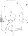
- Fig. 3 shows a section of a manipulator that is guided in its movements by a user while a roll of packaging material is picked up from a pallet.
- Fig. 4 shows the manipulator according to Fig. 3 which can work without user intervention and in an autonomous manner to insert the roll of packaging material into the packaging machine.
- FIG. 1 The schematic perspective view of the Fig. 1 shows in sections a first embodiment of a packaging machine 10 according to the invention.
- the Fig. 1 also a conceivable implementation of an embodiment for the inventive method described above.
- Fig. 1 In the packaging machine 10, flat packaging material such as shrink film or packaging film is processed, which is not shown in detail here.
- the representation of the Fig. 1 is rather intended to illustrate the handling of this packaging material when supplying the packaging machine 10 with new consumption units.
- the packaging material ie the shrink film or packaging film, is wound on large rolls 12 which, due to their weight, cannot usually be handled manually.
- New rolls 12 can be fed to the packaging machine 10 as required by means of a manipulator 14 to be described in more detail below.
- individual new rolls 12 can be one of the two installation positions 18 or 20, while in the other installation position 20 or 18 there is still a used or partially used roll 24, from which a material web located thereon is still unwound during the insertion of the respective new roll 12, which is processed in the packaging machine 10 as packaging material.
- the new rolls 12 are each composed of the wound flat packaging material or the packaging or shrink film and a core 26 on which the packaging material or the shrink film is wound.
- the manipulator 14 or the articulated arm robot 16 dips into the front side of a core 26 of a new roll 12 via a holding mandrel 30 movably arranged at the end of its movable boom arm 22.
- An arm section 22 of the manipulator 14 or the articulated arm robot 16 can be rotated about an axis of rotation for this purpose.
- the cross-sectional diameter of the holding mandrel 30 is enlarged so that the new roll 12 is clamped onto the holding mandrel 30.
- the core 26 is hollow-cylindrical and the shape of the retaining mandrel 30 corresponds thereto, so that the retaining mandrel 30 is connected to an inner surface of the core 26 via its outer circumference for clamping the new roll 12 and can grip it reliably.
- the horizontal conveyor device 28 can provide the manipulator 14 or the articulated robot 16 with new rolls 12 in an uninterrupted sequence, so that when a new roll 12 is removed from the horizontal conveyor device 28, another new roll 12 is moved in the direction of the manipulator 14 or moves up in the direction of the manipulator 14.
- the horizontal conveyor device 28 can be clocked as required or run continuously at a constant speed. operated. Their operation is determined by a manipulator control 32, only indicated schematically here, which can not only control the horizontal conveyor device 28 in its conveying speed and/or timing, but also the boom arm 22 of the manipulator 14 in its movements.
- the manipulator control 32 processes the signals 34 of at least one room monitoring device 36, which can be formed, for example, by an optical detection device such as a camera or by a light grid.
- the space monitoring device 36 detects and monitors a movement space 38 of the articulated robot 16 and in particular the movements of its boom arm 22, which also means the exact movements of the boom arm 22 with the pivotally mounted holding pin 30 in relation to each new roll 12 to be detected.
- the movement space 38 which can be detected optically by means of a camera or light grid of the space monitoring device 36, is shown in the illustration of the Fig. 1 For better illustration, it is indicated by a fan of rays with broken lines.
- a lifting device 40 positioned in the area of the horizontal conveyor 28, which is operated by a user 42 and via which new rolls 12 can be placed upright on the horizontal conveyor 28.
- the new rolls 12 can, for example, be delivered upright on a pallet 44, from which the user 42 can receive them using the lifting device 40, whose movements he can control, and place them on the horizontal conveyor 28 using a holding pin 46 located there and pointing vertically downwards.
- a working area of the lifting device 40 therefore extends over the pallet 44 and over a section of the horizontal conveyor 28.
- this control and feed variant shown is only one example of many alternatives. Continuous feed variants are also possible, which do not require any manually assisted handling, as can be seen from the Fig. 1 is described.
- a feed not structured in this way it may be useful, for example, to provide an intermediate storage area for the new rolls 12 in the movement area 38 of the manipulator 14 or articulated arm robot 16, in order to be able to deposit the rolls 12 there if the holding mandrel 30 of the articulated arm robot 16 does not grasp them in the correct direction of rotation, to pull the holding mandrel 30 out of the core 26 and to grasp the roll 12 again at its other end face in order to move it in the required direction of rotation for the Installation positions 18 or 20 in the packaging machine 10.
- Fig. 1 In the variant of the packaging machine 10 shown, it remains the task of the user 42 to ensure the correct positioning of the rollers 12 on the horizontal conveyor device 28, in particular with regard to their correct direction of rotation in the respective installation position 18 or 20.
- the Fig. 1 also shows a container 48 which is open at the top and is located in the working area 38 of the manipulator 14. If the supply of packaging material or shrink film of one of the rolls 12 or 24 placed in the packaging machine 10 is exhausted, the core 26 of an empty roll 24 made of cellulose, plastic, wood or cardboard is removed from the packaging machine 10 by means of the articulated arm robot 16 and placed in the container 48. Only after the core 26 has been removed can a new roll 12 be inserted into the respective installation position 18 or 20 of the packaging machine 10, so that the manipulator 14 or the articulated arm robot 16 first removes the core 26 and then inserts a new roll 12 into the respective installation position 18 or 20.
- the horizontal conveyor device 28 and some modules of the packaging machine 10 can also be connected to the manipulator control 32 via signal technology.
- Some of the operationally relevant parameters are sensibly recorded by means of the room monitoring device 36, processed by the manipulator control 32 and the data obtained in this way are made available in processed form to the packaging machine 10 and the manipulator 14 so that the latter can ensure that the rolls 12 are positioned as precisely as possible in the installation positions 18 and 20 and the modules of the packaging machine 10 responsible for this can ensure that the material webs are unwound as precisely as possible.
- the manipulator control 32 can provide for movement control of the manipulator 14 formed by the articulated arm robot 16, which enables exact positioning and feeding of the new rolls 12 as well as their handling, even if the exact position of the rolls 12 on the horizontal conveyor device 28 cannot be guaranteed in every case, in particular when the rolls 12 are positioned manually by means of the lifting device 40. Nevertheless, it is important to ensure the exact detection of each new roll 12 by the holding mandrel 30 of the articulated arm robot 16 with the aid of precisely specified movement routines of the manipulator control 32, as well as an exact positioning of the Rollers 12 in the respective installation positions 18 and/or 20 within the packaging machine 10.
- the schematic perspective view of the Fig. 2 illustrates a second embodiment of the packaging machine 10 according to the invention as well as a useful implementation of an embodiment for the method according to the invention.
- the packaging machine 10 does not differ significantly from the previously described variant according to Fig. 1 .
- the in Fig. 2 The second variant of the device 10 shown does not have a horizontal conveyor, but instead receives the new rolls 12 on pallets 44, with each pallet 44 having four rolls 12 arranged upright, which are each picked up individually by the manipulator 14 designed as an articulated arm robot 16 and inserted into the packaging machine 10.
- the manipulator 14 or the articulated arm robot 16 dips into the front of a core 26 of a new roll 12 via the holding mandrel 30 movably arranged at the end of its movable boom arm 22, as already shown in the Fig. 1 was explained.
- An arm section of the manipulator 14 or the articulated arm robot 16 can be rotated about a rotation axis for this purpose.
- the cross-sectional diameter of the holding mandrel 30 is increased so that the new roll 12 is clamped to the holding mandrel 30.
- the core 26 is hollow-cylindrical, the shape of the holding mandrel 30 corresponding to this, so that the holding mandrel 30 is connected to an inner surface of the core 26 via its outer circumference for clamping the new roll 12.
- the pallets 44 are regularly delivered to the movement area 38, providing the manipulator 14 or the articulated arm robot 16 with new rollers 12 in an uninterrupted sequence, so that when all new rollers 12 are removed from one of the pallets 44, this empty pallet 44 can be exchanged for a new pallet 44 with a further four rollers 12, which in turn must be placed in the movement area 38 of the manipulator 14.
- This delivery can be made using suitable industrial trucks, e.g. using so-called AGVs (driverless or driverless transport systems), which can be formed by self-driving, remote-controlled and/or transport vehicles with their own sensor systems for steering, which can, for example, transport a pallet 44 with rollers 12 placed on it into the movement area 48.
- AGVs driverless or driverless transport systems
- Such transport systems or AGVs can be operated in a timed manner as required. Their operation can be timed and controlled by the manipulator control 32, which can not only control the AGVs (not shown here) in their movements, in their respective conveying speed and/or timing, but also controls the manipulator 14 in its movements for exchanging the rollers 12 in the packaging machine 10.
- the manipulator control 32 also processes the signals 34 of the room monitoring device 36, which also applies to the variant according to Fig. 2 in particular by an optical detection device, a camera, a light grid or optionally also by ultrasonic monitoring or the like.
- the room monitoring device 36 is also important for monitoring the movement area 38 of the articulated arm robot 16, since the robot is operated in a different mode while a user 42 is inside the movement area 38 than when the user 42 is outside the movement area 38.
- the optically formed by a camera for example, The movement area 38 detectable by the room monitoring device 36 is shown in the Fig. 2 indicated by an ellipse with broken lines.
- an intermediate storage area 50 for the optional storage of new rolls 12 is located within the movement space 38 of the manipulator 14 and in its immediate vicinity.
- the intermediate storage area 50 can be used to ensure the indispensable positioning of each roll 12 in accordance with the direction of rotation when it is inserted into the packaging machine 10 when the direction of rotation of the rolls 12 is not normally defined on the pallets 44.
- the holding mandrel 30 of the articulated arm robot 16 grasps each individual roll 12 that is on the pallet 44 without the direction of rotation being checked.
- the roll 12 can be deposited on the intermediate storage unit 50 by means of an appropriate movement control of the articulated arm robot 16, after which the holding mandrel 30 is pulled out of the core 26 of the deposited roll 12 in order to grasp the roll 12 again at its other end face in order to be able to then insert it in the required direction of rotation for the installation positions 18 or 20 in the packaging machine 10.
- the design of the intermediate storage 50, its exact function and its interaction with the manipulator 14 and, if applicable, with the room monitoring device 36 are not of any further interest here.
- the one in Fig. 2 The user 42 standing within the movement space 38 normally only stays there for maintenance purposes and/or for programming purposes, but not during the ongoing regular handling operation of the manipulator 14, which can also be controlled by the space monitoring device 36 if necessary.
- FIG. 2 the container 48 which is open at the top and is located in the working area 38 of the manipulator 14 formed by the articulated arm robot 16 can be seen. If the supply of packaging material or shrink film of a roll 12 or 24 placed in the packaging machine 10 is exhausted, the core 26 of an empty roll 24 consisting of cellulose, plastic, wood or cardboard is removed from the packaging machine 10 by means of the articulated arm robot 16 and placed in the container 48. Only after the core 26 has been removed can a new roll 12 be inserted into the respective installation position 18 or 20 of the packaging machine 10, so that the manipulator 14 or the articulated arm robot 16 first removes the core 26 and then inserts a new roll 12 into the respective installation position 18 or 20.
- the schematic representations of the Figures 3 and 4 show a part of the articulated arm robot 16, which forms the manipulator 14 for handling the rolls 12 on and in the packaging machine 10.
- the pivotable boom arm or the arm section 22 of the articulated arm robot 16 is pivotable around the Fig. 3 horizontally extending axis 52, so that the holding mandrel 30 of the articulated arm robot 16 can be aligned with a vertical orientation of its longitudinal axis for immersion in the core 26 of the respective new roll 12.
- the new roll 12 can be rotated about the axis 52 by a renewed pivoting movement of the gripping arm 22 and then temporally moved into its respective assigned installation position 18 or 20 (cf. Figures 1 and 2 ) can be used.
- the room monitoring device 36 can be used to detect when the user 42 is located within the movement space 38 (cf. Figures 1 and 2 ) in order to switch the manipulator control 32 to a so-called COBOT mode, in which the extent to which the user 42 directs and specifies the movements of the boom arm 22 and the holding mandrel 30 is detected by sensors, so that the articulated arm robot 16 can follow these specifications or external influences 54 (see double arrow in Fig. 3 ) of the user 42 and can guide the retaining mandrel 30 very precisely to the core 26 of one of the rollers 12 and allow it to immerse itself there.
- COBOT mode in which the extent to which the user 42 directs and specifies the movements of the boom arm 22 and the holding mandrel 30 is detected by sensors, so that the articulated arm robot 16 can follow these specifications or external influences 54 (see double arrow in Fig. 3 ) of the user 42 and can guide the retaining mandrel 30 very precisely to the core 26 of one of the rollers 12 and allow it to immers
- the external influences 54 exerted by the user 42 can also be recorded and stored in the manipulator control 32 in order to be used for creating new or modifying existing movement routines of the program-controlled manipulator 14.
- the manipulator control 32 can be reprogrammed or reprogrammed in the manner described until the automated processes can be resumed by the manipulator 14 without the manual instructions of the user 42 being required.
- the aforementioned sensor system of the manipulator 14 or articulated arm robot 16 can preferably be implemented by evaluating the drive torques for the electric servomotors of the manipulator 14 or the robot 16, from which it can be concluded that there are external influences by the user 42.
- the sensors of the manipulator 14 or robot 16 mentioned here normally know the required drive torques and the electrical behavior of the respective drive motors for the various interacting joint sections, and this largely for all conceivable positions and masses as well as the centers of gravity of the objects or rollers 12 gripped in each case, so that an influence by the user 42 can be concluded from the comparison of the expected drive torques and the expected power consumption with the actually measured values. Since a sensor system functioning in this way can react sensitively to all conceivable manual influences, and since the movement sequences relevant for programming new movement routines can be significantly slowed down compared to pure robot operation, Manual steering allows very precise movement patterns of the manipulator or robot arm to be specified with comparatively little effort.
- the sensor technology in an extended or alternative configuration can also include optical and/or acoustic detection devices such as cameras with downstream image evaluation or ultrasonic sensors with downstream signal evaluation, which record the influences and movements and can also be used to program future movement routines of the robot.
- optical and/or acoustic detection devices such as cameras with downstream image evaluation or ultrasonic sensors with downstream signal evaluation, which record the influences and movements and can also be used to program future movement routines of the robot.
Landscapes
- Engineering & Computer Science (AREA)
- Robotics (AREA)
- Mechanical Engineering (AREA)
- Physics & Mathematics (AREA)
- General Physics & Mathematics (AREA)
- Automation & Control Theory (AREA)
- Manipulator (AREA)
- Container Filling Or Packaging Operations (AREA)
Applications Claiming Priority (1)
| Application Number | Priority Date | Filing Date | Title |
|---|---|---|---|
| DE102023118216.1A DE102023118216A1 (de) | 2023-07-10 | 2023-07-10 | Verpackungsmaschine sowie Verfahren zu deren Betrieb |
Publications (1)
| Publication Number | Publication Date |
|---|---|
| EP4492174A1 true EP4492174A1 (fr) | 2025-01-15 |
Family
ID=91530326
Family Applications (1)
| Application Number | Title | Priority Date | Filing Date |
|---|---|---|---|
| EP24181680.0A Pending EP4492174A1 (fr) | 2023-07-10 | 2024-06-12 | Machine d'emballage et son procédé de fonctionnement |
Country Status (3)
| Country | Link |
|---|---|
| EP (1) | EP4492174A1 (fr) |
| CN (1) | CN223421998U (fr) |
| DE (1) | DE102023118216A1 (fr) |
Families Citing this family (1)
| Publication number | Priority date | Publication date | Assignee | Title |
|---|---|---|---|---|
| US20240293931A1 (en) * | 2023-12-27 | 2024-09-05 | Intel Corporation | Human-collaborative robot ergonomic interaction system |
Citations (7)
| Publication number | Priority date | Publication date | Assignee | Title |
|---|---|---|---|---|
| WO2010054673A1 (fr) * | 2008-11-13 | 2010-05-20 | Abb Technology Ag | Procédé pour commande de robot |
| DE102009051146A1 (de) * | 2008-10-29 | 2011-04-28 | Sms Siemag Ag | Automatisierungskonzept für ein Hütten- oder Walzwerk |
| DE102015208122A1 (de) * | 2015-04-30 | 2016-11-03 | Krones Aktiengesellschaft | Verfahren und Vorrichtung zur Zuförderung, Bereitstellung und zum Austausch von Rollen mit Verpackungsmaterial in einer Verpackungsmaschine |
| US20180043549A1 (en) * | 2016-08-12 | 2018-02-15 | Industrial Technology Research Institute | Robot arm control device and robot arm operation method |
| DE102016215683A1 (de) * | 2016-08-22 | 2018-02-22 | Volkswagen Aktiengesellschaft | Verfahren zur Steuerung einer robotergestützten Bearbeitung eines Werkstückes mittels einer Mensch-Roboter-Kollaboration-Schnittstelle |
| WO2018228727A1 (fr) | 2017-06-12 | 2018-12-20 | Krones Ag | Installation de traitement de récipient équipée d'un robot mobile pour le changement de composant |
| DE102021100035A1 (de) | 2021-01-04 | 2022-07-07 | Krones Aktiengesellschaft | Transportvorrichtung für Vorratsrollen mit aufgewickeltem Verpackungsmaterial |
Family Cites Families (2)
| Publication number | Priority date | Publication date | Assignee | Title |
|---|---|---|---|---|
| DE102008063680A1 (de) * | 2008-10-10 | 2010-04-15 | Abb Ag | Verfahren zum Einlernen (Teachen) eines Industrieroboters sowie ein entsprechend ausgestatteter Industrieroboter |
| DE102015208118A1 (de) * | 2015-04-30 | 2016-11-03 | Krones Aktiengesellschaft | Verfahren und Vorrichtung zur Zuförderung, Bereitstellung und zum Austausch von Rollen mit Verpackungsmaterial in einer Verpackungsmaschine |
-
2023
- 2023-07-10 DE DE102023118216.1A patent/DE102023118216A1/de active Pending
-
2024
- 2024-06-12 EP EP24181680.0A patent/EP4492174A1/fr active Pending
- 2024-07-05 CN CN202421579228.6U patent/CN223421998U/zh active Active
Patent Citations (7)
| Publication number | Priority date | Publication date | Assignee | Title |
|---|---|---|---|---|
| DE102009051146A1 (de) * | 2008-10-29 | 2011-04-28 | Sms Siemag Ag | Automatisierungskonzept für ein Hütten- oder Walzwerk |
| WO2010054673A1 (fr) * | 2008-11-13 | 2010-05-20 | Abb Technology Ag | Procédé pour commande de robot |
| DE102015208122A1 (de) * | 2015-04-30 | 2016-11-03 | Krones Aktiengesellschaft | Verfahren und Vorrichtung zur Zuförderung, Bereitstellung und zum Austausch von Rollen mit Verpackungsmaterial in einer Verpackungsmaschine |
| US20180043549A1 (en) * | 2016-08-12 | 2018-02-15 | Industrial Technology Research Institute | Robot arm control device and robot arm operation method |
| DE102016215683A1 (de) * | 2016-08-22 | 2018-02-22 | Volkswagen Aktiengesellschaft | Verfahren zur Steuerung einer robotergestützten Bearbeitung eines Werkstückes mittels einer Mensch-Roboter-Kollaboration-Schnittstelle |
| WO2018228727A1 (fr) | 2017-06-12 | 2018-12-20 | Krones Ag | Installation de traitement de récipient équipée d'un robot mobile pour le changement de composant |
| DE102021100035A1 (de) | 2021-01-04 | 2022-07-07 | Krones Aktiengesellschaft | Transportvorrichtung für Vorratsrollen mit aufgewickeltem Verpackungsmaterial |
Also Published As
| Publication number | Publication date |
|---|---|
| CN223421998U (zh) | 2025-10-10 |
| DE102023118216A1 (de) | 2025-01-16 |
Similar Documents
| Publication | Publication Date | Title |
|---|---|---|
| EP3288873B1 (fr) | Procédé et dispositif d'acheminement, de fourniture et d'échange de rouleaux comportant un matériau d'emballage dans une machine d'emballage | |
| EP3288871B1 (fr) | Procédé et dispositif d'acheminement, de fourniture et d'échange de rouleaux comportant un matériau d'emballage dans une machine d'emballage | |
| DE102015208102B4 (de) | Verfahren und Vorrichtung zur Zuförderung, Bereitstellung und zum Austausch von Rollen mit Verpackungsmaterial in einer Verpackungsmaschine | |
| EP3212549B1 (fr) | Procédé et dispositif de manipulation d'un matériau plat et/ou en feuille enroulé sur des rouleaux | |
| EP3638616B1 (fr) | Machine de traitement des recipients avec robot mobil pour changer des composants | |
| EP3288875A1 (fr) | Procédé et dispositif d'acheminement, de fourniture et d'échange de rouleaux comportant un matériau plat et/ou sous forme de film enroulé sur ces derniers | |
| EP3212552B1 (fr) | Procédé et dispositif de manipulation d'un matériau plat et/ou en feuille enroulé sur des rouleaux | |
| WO2023051969A1 (fr) | Robot mobile et procédé de changement d'un rouleau d'étiquettes sur un ensemble d'étiquetage | |
| DE102015208118A1 (de) | Verfahren und Vorrichtung zur Zuförderung, Bereitstellung und zum Austausch von Rollen mit Verpackungsmaterial in einer Verpackungsmaschine | |
| DE202015102191U1 (de) | Vorrichtung zur Zuförderung, Bereitstellung und zum Austausch von Rollen mit Verpackungsmaterial in einer Verpackungsmaschine | |
| EP4271635A1 (fr) | Dispositif de transport pour rouleaux d'alimentation sur lesquels est enroulé un matériau d'emballage | |
| EP4492174A1 (fr) | Machine d'emballage et son procédé de fonctionnement | |
| EP1798174B1 (fr) | Dispositif et méthode pour la manipulation de bobines dans une cellule d'automatisation et une cellule d'automatisation | |
| DE102016200581B4 (de) | Verfahren zur Zuförderung, Bereitstellung und zum Austausch von Rollen mit Verpackungsmaterial in einer Verpackungsmaschine | |
| DE112018008072T5 (de) | Montagesubstrat-Fertigungssystem, Bauteilmontagesystem und Verfahren zum Transport eines Gehäusekörpers | |
| DE102018131992A1 (de) | Verfahren und Vorrichtung zum Umgang mit zur Verpackung von Artikeln ausgebildetem Flach- und/oder Folienmaterial | |
| EP3288874B1 (fr) | Machine d'emballage et procédé d'acheminement, de fourniture et d'échange de rouleaux comportant un matériau d'emballage | |
| DE102016215025A1 (de) | Verfahren und Vorrichtung zum Umgang mit Vorratsrollen, welche auf einem Rollenkern mit einer Vielzahl an Wicklungen Verpackungsmaterial tragen | |
| DE102016206711A1 (de) | Verfahren und Vorrichtung zum Umgang mit auf Rollen aufgewickeltem Verpackungsmaterial | |
| DE102016206183A1 (de) | Verfahren und Vorrichtung zur Bereitstellung von auf Rollen aufgewickeltem Verpackungsmaterial für Artikel wie Getränkebehältnisse oder dergleichen | |
| DE102024130167A1 (de) | Verfahren zum Betreiben einer automatisierten Produktionsanlage, automatisiertes Arbeitssystem und Computerprogrammprodukt | |
| DE102016206172A1 (de) | Vorrichtung und Verfahren zur Bereitstellung von auf Rollen aufgewickeltem Verpackungsmaterial für Artikel wie Getränkebehältnisse oder dergleichen | |
| WO2016206930A1 (fr) | Machine d'emballage et procédé pour l'acheminement, la mise à disposition et l'échange de rouleaux présentant un matériau d'emballage dans une telle machine d'emballage |
Legal Events
| Date | Code | Title | Description |
|---|---|---|---|
| PUAI | Public reference made under article 153(3) epc to a published international application that has entered the european phase |
Free format text: ORIGINAL CODE: 0009012 |
|
| STAA | Information on the status of an ep patent application or granted ep patent |
Free format text: STATUS: THE APPLICATION HAS BEEN PUBLISHED |
|
| AK | Designated contracting states |
Kind code of ref document: A1 Designated state(s): AL AT BE BG CH CY CZ DE DK EE ES FI FR GB GR HR HU IE IS IT LI LT LU LV MC ME MK MT NL NO PL PT RO RS SE SI SK SM TR |
|
| STAA | Information on the status of an ep patent application or granted ep patent |
Free format text: STATUS: REQUEST FOR EXAMINATION WAS MADE |
|
| 17P | Request for examination filed |
Effective date: 20250709 |