EP4492353A2 - Rauchdetektionsvorrichtung, streulichtsensor der rauchdetektionsvorrichtung und verfahren zur detektion eines rauchs mittels der vorrichtung - Google Patents
Rauchdetektionsvorrichtung, streulichtsensor der rauchdetektionsvorrichtung und verfahren zur detektion eines rauchs mittels der vorrichtung Download PDFInfo
- Publication number
- EP4492353A2 EP4492353A2 EP24216320.2A EP24216320A EP4492353A2 EP 4492353 A2 EP4492353 A2 EP 4492353A2 EP 24216320 A EP24216320 A EP 24216320A EP 4492353 A2 EP4492353 A2 EP 4492353A2
- Authority
- EP
- European Patent Office
- Prior art keywords
- photoreceiver
- emission
- light
- emitters
- chamber
- Prior art date
- Legal status (The legal status is an assumption and is not a legal conclusion. Google has not performed a legal analysis and makes no representation as to the accuracy of the status listed.)
- Pending
Links
Images


Classifications
-
- G—PHYSICS
- G08—SIGNALLING
- G08B—SIGNALLING SYSTEMS, e.g. PERSONAL CALLING SYSTEMS; ORDER TELEGRAPHS; ALARM SYSTEMS
- G08B17/00—Fire alarms; Alarms responsive to explosion
- G08B17/10—Actuation by presence of smoke or gases, e.g. automatic alarm devices for analysing flowing fluid materials by the use of optical means
- G08B17/103—Actuation by presence of smoke or gases, e.g. automatic alarm devices for analysing flowing fluid materials by the use of optical means using a light emitting and receiving device
- G08B17/107—Actuation by presence of smoke or gases, e.g. automatic alarm devices for analysing flowing fluid materials by the use of optical means using a light emitting and receiving device for detecting light-scattering due to smoke
-
- G—PHYSICS
- G08—SIGNALLING
- G08B—SIGNALLING SYSTEMS, e.g. PERSONAL CALLING SYSTEMS; ORDER TELEGRAPHS; ALARM SYSTEMS
- G08B17/00—Fire alarms; Alarms responsive to explosion
- G08B17/10—Actuation by presence of smoke or gases, e.g. automatic alarm devices for analysing flowing fluid materials by the use of optical means
- G08B17/11—Actuation by presence of smoke or gases, e.g. automatic alarm devices for analysing flowing fluid materials by the use of optical means using an ionisation chamber for detecting smoke or gas
- G08B17/113—Constructional details
Definitions
- the invention relates to a scattered light sensor that is mounted in a field of fire alarm, in particular, in a smoke detection device for detecting the smoke by detecting a scattered light emission.
- smoke detectors comprising a photoelectric smoke sensor are widely used in commercial and residential rooms, as well as serve as an effective fire prevention tool.
- One of the most widespread sensors are photoelectrical smoke sensors which operate according to a light scattering principle, owing to their accuracy, reliability and safety. Their important operation parameter, as well as in any other smoke sensor, is an ability to provide a maximum low level of false actuations, thereby enabling to increase the sensor's operation efficiency significantly.
- a structure of the most currently existing photoelectrical sensors utilizes an infrared (IR) emitter and a photoreceiver which are arranged in an optical so-called “smoke" chamber.
- IR infrared
- Photoreceiver which are arranged in an optical so-called "smoke" chamber.
- Their operation principle implies that a light from the IR emitter in a normal mode, i.e., when an air-gas mixture is present in the smoke chamber, does not get on the photoreceiver, since the light is not directed to the photoreceiver directly, but when external factors such as smoke, steam, dust etc. enter the air-gas mixture, the light from the emitter will be refracted and the photoreceiver will receive the scattered light reflected from an object, thereby causing an alarm signal.
- a drawback that results from using these sensors in the smoke detection devices is that they do not have any resolution, since such sensor reacts not only to the smoke, but to all non-transparent and semi-transparent objects, including a water steam and aerosols, thereby causing its frequent false actuation and inefficiency of use in dusty, gas-contaminated or humid environments.
- the smoke detection devices started to utilize photoelectrical scattered light sensors which utilize a plurality of emission sources having different wavelengths.
- the operation principle of these sensors implies that a reaction of emission of different wavelengths in response to external factors within the air environment is different, while comparison and analysis of a data of a plurality of emissions enable to detect a presence of the smoke itself with a higher accuracy, thereby reducing false alarms.
- a prior art teaches a wide range of devices and methods for detecting a smoke using a photoelectrical scattered light sensor, and the applicant has selected several technical solutions among them, which are the closest to the proposed group of inventions in terms of a set of essential features.
- a smoke detector comprises a housing with a chamber that receives environmental particles such as, e.g., smoke or steam, a photoreceiver for receiving a light reflected from the chamber along a receiving axis, first, second and third emitters for emitting a light of different wavelengths into the chamber at different angles relative to the receiving axis.
- the smoke detection device further comprises a control unit that is configured to determine whether an alarm signal should be provided based on output signals generated by the photoreceiver resulting from light emitted into the chamber by the first, second, and third emitters, environmental particles towards the photoreceiver.
- control unit executes the following operations: activating the photoreceiver; activating the first light emitter that generates the emission into the chamber for receiving by the photoreceiver, whereupon the photoreceiver generates a first output signal; receiving and filtering the first output signal from the photoreceiver and determining whether the received and filtered first output signal exceeds a given threshold; if the threshold is exceeded, activating the second and the third light emitters which generate the emission into the chamber for receiving by the photoreceiver, whereupon the photoreceiver generates a second and a third signals respectively; calculating first, second and third ratios of the output signals based on values of the first, second and third output signals, and determining whether the alarm signal should be activated.
- the first ratio of the signals may comprise relative levels of the first and second output signals
- the second ratio of the signals may comprise, e.g., relative levels of the first and third signals
- the third ratio of the output signals may comprise relative levels of the second and third output signals. If a current state of the chamber should activate the alarm based on the values of the first, second and third ratios of the signals, the control unit further determines whether durations of the first, second and third output signals match those which are suitable for activation of the alarm, i.e., the first, second and third durations of the output signal are used by the control unit to identify false alarm scenarios or incorrect parameters of the photoreceiver.
- a drawback of the proposed technical solution is a complex algorithm for identifying whether the activation of the alarm signal is required based on determination of the ratios of the signals from three light emitters, as well as the fact that the optical chamber of the photoelectrical smoke sensor comprises a grid for receiving the environmental particles such as smoke or steam that is not equipped with an aerodynamic tunnel which is intended to effectively guide the particles towards the optical chamber.
- An application US2022120672 A1 dated April 21, 2022 teaches a smoke detection device comprising a casing having a smoke detection chamber provided therein, and a detector comprising a first light-emitting unit, a second light-emitting unit and a light-receiving unit with a photodiode.
- the first light-emitting unit is configured to emit a light having a first wavelength into the smoke detection chamber
- the second light-emitting unit is configured to emit a light having a second wavelength into the smoke detection chamber, wherein the second wavelength is greater than the first wavelength
- the light receiving unit is configured to receive the light emitted by the first and second light-emitting units.
- the control unit calculates a ratio between an intensity of the scattered light that is emitted by the first light-emitting unit and by the second light-emitting unit, and compares this ratio to a threshold, thereby identifying a type of the smoke that is present, i.e., black, gray or white.
- a drawback of the proposed technical solution is that it enables to identify the smoke itself (black, gray or white), but does not avoid a false actuation of the detector in case particles having a greater size, e.g., dust, reached an observation field, since a difference between the wavelengths of the first and second light-emitting units is not sufficient to provide the effective identification of the particles having the greater size, i.e., if the dust particles reach the smoke detection chamber, the false activation of the detector will occur with a high probability, thereby negatively affecting the operation efficiency of the latter.
- a patent US9541501B2 dated January 10, 2017 teaches a smoke detection device having a detection unit that works according to a scattered light principle and comprises a two-color light-emitting diode that is configured to emit particles to be detected, and a a photosensor spectrally sensitive to the particles which are detected by light scattering, wherein the light-emitting diode and the photosensor are arranged relative to each other such that a main optical axis of the light-emitting diode and an optical receiving axis of the photosensor define a light scattering angle.
- the light-emitting diode comprises a first LED chip that is configured to emit a first light beam within a first wavelength range of 460 nm ⁇ 40 nm or 390 nm ⁇ 40 nm, and a second LED chip that is configured to emit a second light beam within a second wavelength range of 940 nm ⁇ 40 nm or 860 nm ⁇ 40 nm, wherein the LED chips are arranged one adjacent another on a holder.
- This technical solution implies a presence of a control unit that is connected to the light-emitting diode and to the detector that is configured to form an alarm signal in case a minimal smoke concentration value is detected.
- a drawback of the proposed technical solution is a complex mounting and adjustment of the detector which comprises the two-color light-emitting diode having two chips as compared, e.g., to a detector having two individual light-emitting diodes, besides, if one of the chips comprised in this light-emitting diode is failed, it will require a complete replacement of the latter.
- a patent KR101963111B1 dated July 31, 2019 teaches a photoelectrical smoke detection device comprising a housing, a control unit having a power unit and a scattered light sensor connected thereto.
- the scattered light sensor comprises an optical smoke detection chamber, two light-emitting elements which emit a light having two wavelengths, and a photoelectrical element.
- a first light-emitting element generates an IR radiation having a wavelength of 850-940 nm
- a second light-emitting device generates a blue light having a wavelength of 400-470 nm.
- the detection device comprises the housing that includes a support plate, a light-blocking wall provided on a top surface of the plate, the wall surrounds open portions of two fixation elements of the light-emitting devices, and a fixation element of the photoelectrical sensor in an open cylindrical shape, wherein a lower fixation portion of the support plate forms concentrical circles having a greater radius as compared to the light-blocking wall and a smaller height in order to block foreign materials from reaching the detector.
- a drawback of the proposed technical solution is a complex structure of the fire detector that does not provide a sufficient level of protection against penetration of the foreign items inside the housing thereof, which items, if present, could distort the detection results and, thus, cause a false actuation of the fire detector.
- the solution implies a simultaneous operation and emission of the light by two light-emitting units, thereby negatively affecting an energy efficiency of said smoke detection device.
- An application EP1868172A2 dated December 19, 2007 also discloses use, in a device for monitoring air for a presence of particles, of two light-emitting blocks of blue and infrared radiation, the blocks are mounted at an angle of 60° relative to an axis of a photoreceiver inside an optical chamber. Due to angular emission, the device maximizes sensitivity of smoke particles detection and minimizes an influence of a background light.
- the application discloses a device for photoelectrical detection of particles, the device comprises a control unit and a scattered light sensor connected thereto, the scattered light sensor comprises an optical chamber with a first emitter, a second emitter, a photoreceiver and a mirror for directing the scattered light from the emitters to the photoreceiver arranged in the optical chamber.
- the emitters emit blue and infrared light respectively, while the photoreceiver has a bandwidth that covers wavelengths of both the first emitter and the second emitter.
- a method for detecting particles by means of this device comprises steps of directing the emission through a scattering volume and mirroring it, by means of the mirror, to the photoreceiver that provides an output signal for the control unit.
- the infrared emitter emits continuously, while the blue emitter remains in a non-operation state until the infrared radiation with the scattering particles causes the photoreceiver to alter the signal level.
- the structure of the smoke detection device displaces a center of the optical chamber from an optimal location of concentration of the particles in air, thereby implying a curved trajectory of orientation of emission beams to the photoreceiver by means of the mirrors which may cause an interference of detection results and, thus, affect the method for detecting particles that is carried out by comparing, in the control unit, the signal levels on the photoreceiver from the scattered radiation that occur during the operation period of both emitters to a threshold.
- An objective of the invention is to provide a maximum sensitivity to a nature of a scattered emission from the gas flow, in particular, sizes of particles which prevail in this gas mixture, at a lower power consumption.
- a scattered light sensor for a smoke detection device comprises a chamber with two emitters and one photoreceiver arranged within the chamber.
- a first emitter has an emission range of 940 nm+/-5%
- a second emitter has an emission range of 470 nm+/-5%
- a photoreceiver has a sensitivity range from 400 nm to 1100 nm.
- the first emitter generates an emission in a cone having a solid angle of maximum 5 degrees
- the second emitter generates an emission in a cone having a solid angle of maximum 9 degrees.
- the first and second emitters and the photoreceiver are arranged along a circumference of the optical chamber with an angle of 15+/-2 degrees formed between an optical axis of each of the emitters and a horizontal plane, an angle of 23+/-2 degrees formed between optical axes of the first and second emitters, and an angle of 22+/-2 degrees formed between an optical axis of the photoreceiver and the horizontal plane.
- internal surface of the optical chamber has a coating that absorbs the emission of the emitters.
- the emission intensity of the emitters within the solid angles of 5 and 9 degrees is at least 15 cd.
- This structural design of the sensor increases its sensitivity and reduces the power consumption.
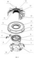
- a scatter light sensor can be configured to be mounted on a circuit board 2 of a smoke detection device.
- a scattered light sensor consists of a photoreceiver 3, a first emitter 4 and a second emitter 5 which are arranged in an optical chamber 6.
- a blue LED is used as the first emitter 4, and it has a wavelength of 940 nm, while an infrared LED is used as the second emitter 5, and it has a wavelength of 470 nm. This selection is caused by providing a maximum difference between the wavelengths and a wide availability of LEDs having these wavelengths. Blue and infrared LEDs manufactured by VISHAY, OSRAM etc. may be used as said emitters.
- Said structural design enables to arrange the emitters substantially opposite to the photoreceiver and to provide their maximum focusing in the central portion of the optical chamber regardless of its dimensions and providing the effective operation of the device at lower energy consumption.
- the scattered light sensor operates according to the principle implying that the light from the emitters in a normal mode, when the chamber is empty, does not get on the photoreceiver, but if the optical chamber is filled with smoke, steam, aerosol etc., the light from the emitters will be refracted and reflected by the gas mixture particles and get on the photoreceiver. Since structure utilizes two emitters having different wavelengths, then upon passage of the light wave through a volume of the portion of the optical chamber, it will be scattered differently, since the particles which penetrate into the chamber have different size and, thus, a different refraction coefficient for the emission with the different wavelength.
Landscapes
- Chemical & Material Sciences (AREA)
- Analytical Chemistry (AREA)
- Business, Economics & Management (AREA)
- Emergency Management (AREA)
- Physics & Mathematics (AREA)
- General Physics & Mathematics (AREA)
- Fire-Detection Mechanisms (AREA)
- Investigating Or Analysing Materials By Optical Means (AREA)
Applications Claiming Priority (2)
| Application Number | Priority Date | Filing Date | Title |
|---|---|---|---|
| UAA202202905A UA130063C2 (uk) | 2022-08-12 | 2022-08-12 | Пристрій виявлення диму та спосіб виявлення диму за допомогою пристрою |
| EP23175100.9A EP4332935A3 (de) | 2022-08-12 | 2023-05-24 | Rauchdetektionsvorrichtung, streulichtsensor der rauchdetektionsvorrichtung und verfahren zur detektion eines rauchs mittels der vorrichtung |
Related Parent Applications (1)
| Application Number | Title | Priority Date | Filing Date |
|---|---|---|---|
| EP23175100.9A Division EP4332935A3 (de) | 2022-08-12 | 2023-05-24 | Rauchdetektionsvorrichtung, streulichtsensor der rauchdetektionsvorrichtung und verfahren zur detektion eines rauchs mittels der vorrichtung |
Publications (2)
| Publication Number | Publication Date |
|---|---|
| EP4492353A2 true EP4492353A2 (de) | 2025-01-15 |
| EP4492353A3 EP4492353A3 (de) | 2025-04-02 |
Family
ID=86603833
Family Applications (2)
| Application Number | Title | Priority Date | Filing Date |
|---|---|---|---|
| EP23175100.9A Pending EP4332935A3 (de) | 2022-08-12 | 2023-05-24 | Rauchdetektionsvorrichtung, streulichtsensor der rauchdetektionsvorrichtung und verfahren zur detektion eines rauchs mittels der vorrichtung |
| EP24216320.2A Pending EP4492353A3 (de) | 2022-08-12 | 2023-05-24 | Rauchdetektionsvorrichtung, streulichtsensor der rauchdetektionsvorrichtung und verfahren zur detektion eines rauchs mittels der vorrichtung |
Family Applications Before (1)
| Application Number | Title | Priority Date | Filing Date |
|---|---|---|---|
| EP23175100.9A Pending EP4332935A3 (de) | 2022-08-12 | 2023-05-24 | Rauchdetektionsvorrichtung, streulichtsensor der rauchdetektionsvorrichtung und verfahren zur detektion eines rauchs mittels der vorrichtung |
Country Status (5)
| Country | Link |
|---|---|
| US (1) | US12223815B2 (de) |
| EP (2) | EP4332935A3 (de) |
| AU (2) | AU2023203439B2 (de) |
| CA (1) | CA3203130A1 (de) |
| UA (1) | UA130063C2 (de) |
Families Citing this family (2)
| Publication number | Priority date | Publication date | Assignee | Title |
|---|---|---|---|---|
| US20250003853A1 (en) * | 2023-06-28 | 2025-01-02 | Texas Instruments Incorporated | Light scattering measurement based on multiple light sources |
| CN117877191B (zh) * | 2024-03-11 | 2024-05-07 | 深圳市千宝通通科技有限公司 | 一种光导烟感探测器及烟感探测方法 |
Citations (8)
| Publication number | Priority date | Publication date | Assignee | Title |
|---|---|---|---|---|
| US20040075056A1 (en) | 2001-09-25 | 2004-04-22 | Bell Kenneth Frazer | High sensitivity particle detection |
| EP1868172A2 (de) | 2003-10-23 | 2007-12-19 | Siemens Schweiz AG | Verfahren zur Montage eines Gehäuses auf einer Leitung und entsprechende Gehäuseanordnung |
| DE202015000820U1 (de) * | 2014-12-01 | 2015-03-04 | Siemens Schweiz Ag | Streulichtrauchmelder mit zwei zweifarbigen Leuchtdioden und einem gemeinsamen Photosensor oder mit einer zweifarbigen Leuchtdiode und mit zwei Photosensoren jeweils in einer Vorwärts- und Rückwärtsstreulichtanordnung |
| US9541501B2 (en) | 2014-12-01 | 2017-01-10 | Siemens Schweiz Ag | Scattered-light smoke detector with a two-color light-emitting diode |
| KR101963111B1 (ko) | 2018-01-23 | 2019-07-31 | 황 금 | 비화재보 발생 방지부를 구비한 광전식 화재감지기 |
| US10769921B2 (en) | 2016-08-04 | 2020-09-08 | Carrier Corporation | Smoke detector |
| US20210372913A1 (en) * | 2018-09-28 | 2021-12-02 | Siemens Schweiz Ag | Scattered Light Smoke Detector Having a Two-Color LED, a Photosensor, and a Wavelength-Selective Polarizer Connected Upstream of the Photosensor or Connected Downstream of the Two-Color LED, and Suitable Use of Such a Polarizer |
| US20220120672A1 (en) | 2019-03-11 | 2022-04-21 | Nohmi Bosai Ltd. | Smoke detector |
Family Cites Families (19)
| Publication number | Priority date | Publication date | Assignee | Title |
|---|---|---|---|---|
| US4156816A (en) * | 1976-09-01 | 1979-05-29 | Telefonaktiebolaget L M Ericsson | Optical fire-detector |
| JPH1123458A (ja) * | 1997-05-08 | 1999-01-29 | Nittan Co Ltd | 煙感知器および監視制御システム |
| US6225910B1 (en) * | 1999-12-08 | 2001-05-01 | Gentex Corporation | Smoke detector |
| US7564365B2 (en) * | 2002-08-23 | 2009-07-21 | Ge Security, Inc. | Smoke detector and method of detecting smoke |
| AU2004290246B2 (en) * | 2003-11-17 | 2010-06-10 | Hochiki Corporation | Smoke sensor using scattering light |
| CN102171733B (zh) * | 2008-10-09 | 2015-04-29 | 报知机株式会社 | 烟检测器 |
| US9915609B1 (en) * | 2012-04-29 | 2018-03-13 | Valor Fire Safety, Llc | System and method of smoke detection using multiple wavelengths of light |
| US8907802B2 (en) * | 2012-04-29 | 2014-12-09 | Valor Fire Safety, Llc | Smoke detector with external sampling volume and ambient light rejection |
| KR101373864B1 (ko) * | 2013-07-02 | 2014-03-12 | 이승철 | 고압반, 저압반, 모터콘트롤반, 분전반 배전반의 전기화재 조기 감지장치 |
| EP2908298B1 (de) * | 2014-02-13 | 2018-04-18 | Siemens Schweiz AG | Rauchmelder nach dem Streulichtprinzip mit einer zweifarbigen Leuchtdiode mit unterschiedlich grossen LED-Chips |
| US9514623B1 (en) * | 2015-05-15 | 2016-12-06 | Google Inc. | Smoke detector chamber architecture and related methods using two different wavelengths of light |
| EP3576063A3 (de) * | 2015-08-13 | 2020-01-29 | Siemens Schweiz AG | Rauchdetektionseinheit mit leuchtdiode und photoempfänger, und mit einem in der leuchtdiode angeordneten led-chip und photosensor zur bestimmung eines alterungsgrads und/oder eines lichtstromkompensationswerts, sowie eine leuchtdiode |
| US10078948B2 (en) * | 2016-01-26 | 2018-09-18 | Honeywell International Inc. | Smoke detector with a double optical chamber |
| EP3779909B1 (de) * | 2018-03-28 | 2022-10-05 | Hochiki Corporation | Brandmelder |
| CN109615816A (zh) * | 2019-01-31 | 2019-04-12 | 中磊电子(苏州)有限公司 | 可避免假警报的烟雾检测器 |
| US11195400B2 (en) * | 2019-02-20 | 2021-12-07 | Jade Bird Fire Co., Ltd. | Smoke detector and method for detecting smoke |
| WO2022013657A1 (en) * | 2020-07-17 | 2022-01-20 | Onpoint Technologies, Llc | Demultiplexing filter and method |
| US11615684B2 (en) * | 2020-11-24 | 2023-03-28 | Pixart Imaging Inc. | Smoke detector |
| US11990024B2 (en) * | 2022-08-01 | 2024-05-21 | Pixart Imaging Inc. | Multi-stage firm alarm device |
-
2022
- 2022-08-12 UA UAA202202905A patent/UA130063C2/uk unknown
-
2023
- 2023-05-23 US US18/322,070 patent/US12223815B2/en active Active
- 2023-05-24 EP EP23175100.9A patent/EP4332935A3/de active Pending
- 2023-05-24 EP EP24216320.2A patent/EP4492353A3/de active Pending
- 2023-06-01 AU AU2023203439A patent/AU2023203439B2/en active Active
- 2023-06-13 CA CA3203130A patent/CA3203130A1/en active Pending
-
2024
- 2024-11-18 AU AU2024264730A patent/AU2024264730A1/en active Pending
Patent Citations (8)
| Publication number | Priority date | Publication date | Assignee | Title |
|---|---|---|---|---|
| US20040075056A1 (en) | 2001-09-25 | 2004-04-22 | Bell Kenneth Frazer | High sensitivity particle detection |
| EP1868172A2 (de) | 2003-10-23 | 2007-12-19 | Siemens Schweiz AG | Verfahren zur Montage eines Gehäuses auf einer Leitung und entsprechende Gehäuseanordnung |
| DE202015000820U1 (de) * | 2014-12-01 | 2015-03-04 | Siemens Schweiz Ag | Streulichtrauchmelder mit zwei zweifarbigen Leuchtdioden und einem gemeinsamen Photosensor oder mit einer zweifarbigen Leuchtdiode und mit zwei Photosensoren jeweils in einer Vorwärts- und Rückwärtsstreulichtanordnung |
| US9541501B2 (en) | 2014-12-01 | 2017-01-10 | Siemens Schweiz Ag | Scattered-light smoke detector with a two-color light-emitting diode |
| US10769921B2 (en) | 2016-08-04 | 2020-09-08 | Carrier Corporation | Smoke detector |
| KR101963111B1 (ko) | 2018-01-23 | 2019-07-31 | 황 금 | 비화재보 발생 방지부를 구비한 광전식 화재감지기 |
| US20210372913A1 (en) * | 2018-09-28 | 2021-12-02 | Siemens Schweiz Ag | Scattered Light Smoke Detector Having a Two-Color LED, a Photosensor, and a Wavelength-Selective Polarizer Connected Upstream of the Photosensor or Connected Downstream of the Two-Color LED, and Suitable Use of Such a Polarizer |
| US20220120672A1 (en) | 2019-03-11 | 2022-04-21 | Nohmi Bosai Ltd. | Smoke detector |
Also Published As
| Publication number | Publication date |
|---|---|
| EP4492353A3 (de) | 2025-04-02 |
| EP4332935A3 (de) | 2024-05-08 |
| AU2023203439B2 (en) | 2024-11-14 |
| AU2023203439A1 (en) | 2024-02-29 |
| US12223815B2 (en) | 2025-02-11 |
| CA3203130A1 (en) | 2024-02-12 |
| UA130063C2 (uk) | 2025-10-29 |
| AU2024264730A1 (en) | 2024-12-05 |
| US20240054875A1 (en) | 2024-02-15 |
| EP4332935A2 (de) | 2024-03-06 |
Similar Documents
| Publication | Publication Date | Title |
|---|---|---|
| EP4492353A2 (de) | Rauchdetektionsvorrichtung, streulichtsensor der rauchdetektionsvorrichtung und verfahren zur detektion eines rauchs mittels der vorrichtung | |
| US9569946B2 (en) | Smoke alarm according to the scattered light principle having a two-color light-emitting diode with different sizes of LED chips | |
| US7239387B2 (en) | Fire detection method and fire detector therefor | |
| EP1508032B3 (de) | Rauchmelder | |
| US20100271220A1 (en) | Detection Device System and Device Thereof | |
| RU2541178C2 (ru) | Светоизлучающий участок, фотоэлектрический датчик дыма и система всасывающего типа для определения присутствия дыма | |
| US8559006B2 (en) | Particulate detector | |
| US20110037971A1 (en) | Smoke detection by way of two spectrally different scattered light measurements | |
| US7847700B2 (en) | System and method for an optical particle detector | |
| US20210123863A1 (en) | Monitoring devices with surface mount technology | |
| CN1261972A (zh) | 烟雾报警器 | |
| RU179257U1 (ru) | Оптический датчик дыма | |
| CA1109541A (en) | Optical smoke detector | |
| US7167098B2 (en) | Testing equipment for a fire alarm | |
| CN111080960A (zh) | 一种带有导光散射结构的烟感探测装置 | |
| JP2024083191A (ja) | 煙感知器 | |
| JPH04205400A (ja) | 煙感知器 | |
| EA047064B1 (ru) | Устройство обнаружения дыма, датчик рассеянного света устройства обнаружения дыма и способ обнаружения дыма с помощью устройства | |
| JP5046552B2 (ja) | 光電式煙感知器 | |
| KR102561893B1 (ko) | 듀얼 광학식 연기 감지장치 | |
| CN112798483A (zh) | 一种扁平化的微型烟雾探测传感器及其工作方法 | |
| RU168853U1 (ru) | Датчик дыма | |
| JP2022183856A (ja) | 検出装置 | |
| JP2021051523A (ja) | 炎感知器 | |
| HU227010B1 (hu) | Eljárás tûz észleléséhez, valamint szórtfény elven mûködõ tûzjelzõ |
Legal Events
| Date | Code | Title | Description |
|---|---|---|---|
| PUAI | Public reference made under article 153(3) epc to a published international application that has entered the european phase |
Free format text: ORIGINAL CODE: 0009012 |
|
| STAA | Information on the status of an ep patent application or granted ep patent |
Free format text: STATUS: THE APPLICATION HAS BEEN PUBLISHED |
|
| AC | Divisional application: reference to earlier application |
Ref document number: 4332935 Country of ref document: EP Kind code of ref document: P |
|
| AK | Designated contracting states |
Kind code of ref document: A2 Designated state(s): AL AT BE BG CH CY CZ DE DK EE ES FI FR GB GR HR HU IE IS IT LI LT LU LV MC ME MK MT NL NO PL PT RO RS SE SI SK SM TR |
|
| PUAL | Search report despatched |
Free format text: ORIGINAL CODE: 0009013 |
|
| AK | Designated contracting states |
Kind code of ref document: A3 Designated state(s): AL AT BE BG CH CY CZ DE DK EE ES FI FR GB GR HR HU IE IS IT LI LT LU LV MC ME MK MT NL NO PL PT RO RS SE SI SK SM TR |
|
| RIC1 | Information provided on ipc code assigned before grant |
Ipc: G08B 17/113 20060101ALI20250227BHEP Ipc: G08B 17/107 20060101AFI20250227BHEP |
|
| STAA | Information on the status of an ep patent application or granted ep patent |
Free format text: STATUS: REQUEST FOR EXAMINATION WAS MADE |
|
| 17P | Request for examination filed |
Effective date: 20251001 |
|
| STAA | Information on the status of an ep patent application or granted ep patent |
Free format text: STATUS: EXAMINATION IS IN PROGRESS |
|
| 17Q | First examination report despatched |
Effective date: 20260211 |