EP4492475A1 - Cellule de contact arrière - Google Patents
Cellule de contact arrière Download PDFInfo
- Publication number
- EP4492475A1 EP4492475A1 EP23856212.8A EP23856212A EP4492475A1 EP 4492475 A1 EP4492475 A1 EP 4492475A1 EP 23856212 A EP23856212 A EP 23856212A EP 4492475 A1 EP4492475 A1 EP 4492475A1
- Authority
- EP
- European Patent Office
- Prior art keywords
- convex
- semiconductor layer
- doped semiconductor
- convex structure
- region
- Prior art date
- Legal status (The legal status is an assumption and is not a legal conclusion. Google has not performed a legal analysis and makes no representation as to the accuracy of the status listed.)
- Pending
Links
Images

Classifications
-
- H—ELECTRICITY
- H10—SEMICONDUCTOR DEVICES; ELECTRIC SOLID-STATE DEVICES NOT OTHERWISE PROVIDED FOR
- H10F—INORGANIC SEMICONDUCTOR DEVICES SENSITIVE TO INFRARED RADIATION, LIGHT, ELECTROMAGNETIC RADIATION OF SHORTER WAVELENGTH OR CORPUSCULAR RADIATION
- H10F77/00—Constructional details of devices covered by this subclass
- H10F77/70—Surface textures, e.g. pyramid structures
-
- H—ELECTRICITY
- H10—SEMICONDUCTOR DEVICES; ELECTRIC SOLID-STATE DEVICES NOT OTHERWISE PROVIDED FOR
- H10F—INORGANIC SEMICONDUCTOR DEVICES SENSITIVE TO INFRARED RADIATION, LIGHT, ELECTROMAGNETIC RADIATION OF SHORTER WAVELENGTH OR CORPUSCULAR RADIATION
- H10F77/00—Constructional details of devices covered by this subclass
- H10F77/10—Semiconductor bodies
- H10F77/14—Shape of semiconductor bodies; Shapes, relative sizes or dispositions of semiconductor regions within semiconductor bodies
- H10F77/147—Shapes of bodies
-
- H—ELECTRICITY
- H10—SEMICONDUCTOR DEVICES; ELECTRIC SOLID-STATE DEVICES NOT OTHERWISE PROVIDED FOR
- H10F—INORGANIC SEMICONDUCTOR DEVICES SENSITIVE TO INFRARED RADIATION, LIGHT, ELECTROMAGNETIC RADIATION OF SHORTER WAVELENGTH OR CORPUSCULAR RADIATION
- H10F10/00—Individual photovoltaic cells, e.g. solar cells
- H10F10/10—Individual photovoltaic cells, e.g. solar cells having potential barriers
- H10F10/14—Photovoltaic cells having only PN homojunction potential barriers
- H10F10/146—Back-junction photovoltaic cells, e.g. having interdigitated base-emitter regions on the back side
-
- H—ELECTRICITY
- H10—SEMICONDUCTOR DEVICES; ELECTRIC SOLID-STATE DEVICES NOT OTHERWISE PROVIDED FOR
- H10F—INORGANIC SEMICONDUCTOR DEVICES SENSITIVE TO INFRARED RADIATION, LIGHT, ELECTROMAGNETIC RADIATION OF SHORTER WAVELENGTH OR CORPUSCULAR RADIATION
- H10F71/00—Manufacture or treatment of devices covered by this subclass
- H10F71/121—The active layers comprising only Group IV materials
-
- H—ELECTRICITY
- H10—SEMICONDUCTOR DEVICES; ELECTRIC SOLID-STATE DEVICES NOT OTHERWISE PROVIDED FOR
- H10F—INORGANIC SEMICONDUCTOR DEVICES SENSITIVE TO INFRARED RADIATION, LIGHT, ELECTROMAGNETIC RADIATION OF SHORTER WAVELENGTH OR CORPUSCULAR RADIATION
- H10F77/00—Constructional details of devices covered by this subclass
- H10F77/10—Semiconductor bodies
- H10F77/14—Shape of semiconductor bodies; Shapes, relative sizes or dispositions of semiconductor regions within semiconductor bodies
- H10F77/148—Shapes of potential barriers
-
- H—ELECTRICITY
- H10—SEMICONDUCTOR DEVICES; ELECTRIC SOLID-STATE DEVICES NOT OTHERWISE PROVIDED FOR
- H10F—INORGANIC SEMICONDUCTOR DEVICES SENSITIVE TO INFRARED RADIATION, LIGHT, ELECTROMAGNETIC RADIATION OF SHORTER WAVELENGTH OR CORPUSCULAR RADIATION
- H10F77/00—Constructional details of devices covered by this subclass
- H10F77/20—Electrodes
- H10F77/206—Electrodes for devices having potential barriers
- H10F77/211—Electrodes for devices having potential barriers for photovoltaic cells
- H10F77/219—Arrangements for electrodes of back-contact photovoltaic cells
-
- H—ELECTRICITY
- H10—SEMICONDUCTOR DEVICES; ELECTRIC SOLID-STATE DEVICES NOT OTHERWISE PROVIDED FOR
- H10F—INORGANIC SEMICONDUCTOR DEVICES SENSITIVE TO INFRARED RADIATION, LIGHT, ELECTROMAGNETIC RADIATION OF SHORTER WAVELENGTH OR CORPUSCULAR RADIATION
- H10F77/00—Constructional details of devices covered by this subclass
- H10F77/30—Coatings
- H10F77/306—Coatings for devices having potential barriers
- H10F77/311—Coatings for devices having potential barriers for photovoltaic cells
-
- H—ELECTRICITY
- H10—SEMICONDUCTOR DEVICES; ELECTRIC SOLID-STATE DEVICES NOT OTHERWISE PROVIDED FOR
- H10F—INORGANIC SEMICONDUCTOR DEVICES SENSITIVE TO INFRARED RADIATION, LIGHT, ELECTROMAGNETIC RADIATION OF SHORTER WAVELENGTH OR CORPUSCULAR RADIATION
- H10F77/00—Constructional details of devices covered by this subclass
- H10F77/70—Surface textures, e.g. pyramid structures
- H10F77/703—Surface textures, e.g. pyramid structures of the semiconductor bodies, e.g. textured active layers
Definitions
- This application relates to the field of solar cell technologies, and in particular, to a back contact solar cell.
- a back contact solar cell is a solar cell in which emitters and metal contacts are arranged on its back surface and no metal electrode is arranged on its front surface. Compared with a solar cell with a metal electrode arranged on its front surface, the back contact solar cell has a higher short-circuit current and photoelectric conversion efficiency, and is one of existing technical directions for realizing efficient crystalline silicon solar cells.
- An objective of this application is to provide a back contact solar cell, to improve the distinguishability between a first doped semiconductor layer and a second doped semiconductor layer, reduce the difficulty in accurately arranging conductive structures having the same polarities as the two types of doped semiconductor layers on the two types of doped semiconductor layers, and avoid short circuit of the back contact solar cell, thereby improving the electrical stability of the back contact solar cell.
- the back contact solar cell includes: a semiconductor substrate, a first doped semiconductor layer, and a second doped semiconductor layer.
- the semiconductor substrate includes a first surface and a second surface opposite to the first surface.
- the second surface includes a first region and a second region arranged alternately in a direction parallel to the second surface.
- a surface of the first region has a first convex structure
- a surface of the second region has a second convex structure.
- a morphology of each convex distributed in the first convex structure is different from a morphology of each convex distributed in the second convex structure.
- the first doped semiconductor layer is formed in or on the first region.
- the second doped semiconductor layer is formed in or on the second region.
- a conductivity type of the second doped semiconductor layer is opposite to a conductivity type of the first doped semiconductor layer.
- the surface of the first region on the second surface has the first convex structure; and the surface of the second region on the second surface has the second convex structure.
- the morphology of each convex distributed in the first convex structure is different from the morphology of each convex distributed in the second convex structure.
- the first doped semiconductor layer is formed on the first region and the second doped semiconductor layer is formed on the second region, in a direction parallel to the surface of the first region, heights of portions of the first doped semiconductor layer are substantially the same, so that a morphology of the first doped semiconductor layer facing away from the semiconductor substrate is substantially the same as the morphology of the first region; and similarly, in a direction parallel to the surface of the second region, heights of portions of the second doped semiconductor layer are substantially the same, so that a morphology of the second doped semiconductor layer facing away from the semiconductor substrate is substantially the same as the morphology of the second region.
- the morphology of the side of the first doped semiconductor layer facing away from the semiconductor substrate is also different from the morphology of the side of the second doped semiconductor layer facing away from the semiconductor substrate, so that specific formation positions of the first doped semiconductor layer and the second doped semiconductor layer on the semiconductor substrate can be well distinguished from each other through the difference.
- first doped semiconductor layer when the first doped semiconductor layer is formed in the first region and the second doped semiconductor layer is formed on the second region, specific formation positions of doped semiconductor layers having different conductivity types may be distinguished from each other through the morphology of the first region and the morphology of the side of the second doped semiconductor layer facing away from the semiconductor substrate.
- the specific formation positions of the doped semiconductor layers having different conductivity types may be distinguished from each other through the morphology of the side of the first doped semiconductor layer facing away from the semiconductor substrate and the morphology of the second region.
- the back contact solar cell compared with existing back contact solar cells including two types of doped semiconductor layers having opposite conductivity types and a same morphology, in the back contact solar cell provided in this application, there is higher distinguishability between the first doped semiconductor layer and the second doped semiconductor layer, so that the difficulty in accurately arranging the conductive structures having the same polarities as the two types of doped semiconductor layers on the first doped semiconductor layer and the second doped semiconductor layer respectively can be reduced, and a risk of short circuit of the back contact solar cell caused by coupling of the first doped semiconductor layer and the second doped semiconductor layer having opposite conductivity types through the conductive structures can be further reduced, thereby improving the electrical stability of the back contact solar cell.
- surfaces of both the first convex structure and the second convex structure are smoother than a surface of a textured structure. Therefore, compared with back contact solar cells with the textured structure on a back surface, in the back contact solar cell provided in this application, surfaces of the first doped semiconductor layer and the second doped semiconductor layer are smoother, facilitating deposition of a surface passivation layer on the surfaces of the two doped semiconductor layers. Therefore, the surface passivation layer forms a denser film with an improved passivation effect, thereby effectively improving an open circuit voltage of the back contact solar cell and improving the photoelectric conversion efficiency of the back contact solar cell.
- the surface of the first region is provided with first grid-shaped grooves recessed toward the semiconductor substrate; and the first convex structure is located in a grid region encircled by the first grid-shaped grooves.
- the first grid-shaped grooves recessed toward the semiconductor substrate may be provided through manners such as laser etching on the formed first region, so that a part of the first region located on inner sides of the first grid-shaped grooves forms the first convex structure.
- each convex distributed in the first convex structure is obvious, helping distinguish a specific formation position of the first doped semiconductor layer through the first convex structure.
- the surface of the second region is provided with second grid-shaped grooves recessed toward the semiconductor substrate; and the second convex structure is located in a grid region encircled by the second grid-shaped grooves.
- the first convex structure is a first pyramid base structure obtained through polishing treatment.
- the first convex structure may be obtained by performing polishing treatment on a pyramid structure originally formed on the surface of the first region and removing an upper half part of the pyramid structure, to obtain the first pyramid base structure.
- the first pyramid base structure is a microstructure.
- the first convex structure is the first pyramid base structure obtained through polishing treatment
- thinning to a thickness of the semiconductor substrate for forming the first convex structure on the surface of the first region may be reduced, so that a probability that light is absorbed after being incident to the semiconductor substrate is further increased while production of a thin back contact solar cell is implemented, thereby improving the photoelectric conversion efficiency of the back contact solar cell.
- the second convex structure is a second pyramid base structure obtained through polishing treatment.
- the second pyramid base structure obtained through polishing treatment.
- a surface of each convex distributed in the first convex structure facing away from the semiconductor substrate is in a shape of a first quasi-regular polygon; a surface of each convex distributed in the second convex structure facing away from the semiconductor substrate is in a shape of a second quasi-regular polygon; and a side length of the first quasi-regular polygon is different from a side length of the second quasi-regular polygon.
- a size of the first quasi-regular polygon is different from a size of the second quasi-regular polygon.
- the specific formation positions of the first doped semiconductor layer and the second doped semiconductor layer may be distinguished from each other more intuitively through at least a size difference obtained by comparing quasi-regular polygons corresponding to the convexs on the surface of the first doped semiconductor layer and the surface of the second doped semiconductor layer.
- a height of each convex distributed in the first convex structure is different from a height of each convex distributed in the second convex structure.
- the specific formation positions of the first doped semiconductor layer and the second doped semiconductor layer may be distinguished from each other through at least a difference obtained by comparing the heights corresponding to the convexs on the surface of the first doped semiconductor layer and the surface of the second doped semiconductor layer. Therefore, a possible solution for distinguishing between the first doped semiconductor layer and the second doped semiconductor layer is provided, and the applicability of the back contact solar cell provided in this application in different application scenarios is improved.
- the side length of the first quasi-regular polygon is less than the side length of the second quasi-regular polygon.
- the height of each convex distributed in the first convex structure is greater than the height of each convex distributed in the second convex structure.
- the surface of the second region having the second convex structure is smoother than the surface of the first region having the first convex structure, so that a passivation effect of the surface passivation layer to a surface of the second doped semiconductor layer can be enhanced, thereby further improving the photoelectric conversion efficiency of the back contact solar cell.
- a region corresponding to a greater convex height is the formation position of the first doped semiconductor layer; and a region corresponding to a smaller convex height is the formation position of the second doped semiconductor layer, so that the first doped semiconductor layer and the second doped semiconductor layer can be distinguished from each other easily.
- first convex structure and the second convex structure are respectively the first pyramid base structure and the second pyramid base structure obtained through polishing treatment
- a height is inversely proportional to a side length of each of the first pyramid base structure and the second pyramid base structure
- the side length of the first quasi-regular polygon is less than the side length of the second quasi-regular polygon.
- a doping concentration of the first doped semiconductor layer is less than a doping concentration of the second doped semiconductor layer.
- contact resistance between a doped semiconductor layer and a conductive structure is inversely proportional to a doping concentration of the doped semiconductor layer.
- the side length of the second quasi-regular polygon is greater than the side length of the first quasi-regular polygon, the surface of the second region having the second convex structure is smoother than the surface of the first region having the first convex structure, so that the surface of the second doped semiconductor layer is smoother than the surface of the first doped semiconductor layer.
- a smooth surface corresponds to a small specific surface area.
- a thickness of the passivation material on the second doped semiconductor layer is greater than a thickness of the passivation material on the first doped semiconductor layer.
- a thickness of the surface passivation layer on the second doped semiconductor layer with a greater doping concentration is greater than a thickness of the surface passivation layer on the first doped semiconductor layer with a smaller doping concentration.
- the thickness of the surface passivation layer on the second doped semiconductor layer is large, so that a problem that a part of the surface passivation layer on the second doped semiconductor layer is prematurely burnt through due to a long sintering time or a high sintering temperature can be resolved, thereby ensuring good contact of the first doped semiconductor layer and the second doped semiconductor layer and improving the electrical performance of the back contact solar cell.
- the first convex structure and the second convex structure each include a top surface and a bottom surface opposite to the top surface; a surface of each of the first convex structure and the second convex structure facing away from the semiconductor substrate is defined as the top surface; and in a case that the side length of the first quasi-regular polygon is less than the side length of the second quasi-regular polygon, the top surface of the second convex structure is recessed toward the semiconductor substrate relative to the top surface of the first convex structure.
- the top surface of the second convex structure is recessed toward the semiconductor substrate relative to the top surface of the first convex structure, so that a surface of the second doped semiconductor layer facing away from the semiconductor substrate is also recessed inward toward the semiconductor substrate relative to a surface of the first doped semiconductor layer facing away from the semiconductor substrate.
- a height difference between surfaces of parts of the surface passivation layer on the first region and the second region can also be eliminated by recessing the surface of the second doped semiconductor layer facing away from the semiconductor substrate inward toward the semiconductor substrate relative to the surface of the first doped semiconductor layer facing away from the semiconductor substrate.
- first electrode and a second electrode subsequently formed may respectively run through the surface passivation layer through corresponding types of electrode windows, thereby reducing contact resistance at the first electrode and the second electrode.
- the first electrode and the second electrode subsequently formed do not extend into doped semiconductor layers having corresponding conductivity types, thereby ensuring that carrier recombination rates at both the first electrode and the second electrode are low and improving the photoelectric conversion efficiency of the back contact solar cell.
- the side length of the first quasi-regular polygon ranges from 0.5 ⁇ m to 20 ⁇ m; and the height of each convex distributed in the first convex structure ranges from 0.5 ⁇ m to 5 ⁇ m.
- the side length of the first quasi-regular polygon has a specific optional range, so that there is no need to impose a strict requirement on treatment conditions such as a polishing time to process a side length of each convex on the surface of the first region to a fixed value, thereby reducing the difficulty of the treatment such as polishing.
- the first quasi-regular polygon has a micron-sized side length, so that the morphology of the first region is more obvious, and the specific formation positions of the first doped semiconductor layer and the second doped semiconductor layer can be distinguished from each other more easily.
- beneficial effects of setting the height of each convex distributed in the first convex structure to 0.5 ⁇ m to 5 ⁇ m reference may be made to the beneficial effects when the side length of the first quasi-regular polygon ranges from 0.5 ⁇ m to 20 ⁇ m described above, and details are not described herein again.
- the side length of the second quasi-regular polygon ranges from 10 ⁇ m to 50 ⁇ m; and the height of each convex distributed in the second convex structure ranges from 0.5 ⁇ m to 10 ⁇ m.
- the side length of the first quasi-regular polygon ranges from 0.5 ⁇ m to 20 ⁇ m described above.
- a thickness of the second doped semiconductor layer generally ranges from 20 nm to 600 nm.
- each convex on the second region ranges from 10 ⁇ m to 50 ⁇ m, and the side length is far greater than the thickness of the second doped semiconductor layer. Based on this, no matter whether the second doped semiconductor layer is formed in or on the second region, the surface of the second doped semiconductor layer facing away from the semiconductor substrate has an obvious convex morphology, helping improve the distinguishability of the formation position of the second doped semiconductor layer.
- beneficial effects of setting the height of each convex distributed in the second convex structure to 0.5 ⁇ m to 10 ⁇ m
- each convex distributed in the first convex structure and each convex distributed in the second convex structure both include a top surface and a bottom surface opposite to the top surface; a surface of each convex distributed in the first convex structure and each convex distributed in the second convex structure facing away from the semiconductor substrate is defined as the top surface; an area of the top surface of each convex distributed in the first convex structure is less than an area of the bottom surface of the convex; and an area of the top surface of each convex distributed in the second convex structure is less than an area of the bottom surface of the convex.
- both the top surface and the bottom surface of each convex distributed in the first convex structure are in a shape of a quasi-regular polygon; and both the top surface and the bottom surface of each convex distributed in the second convex structure are in a shape of a quasi-regular polygon.
- each convex distributed in the first convex structure and each convex distributed in the second convex structure both have a regular quasi-prism morphology.
- surfaces of the first region and the second region having convexs with the regular quasi-prism morphology are flatter, helping improve the compactness of the parts of the surface passivation layer formed on the first region and the second region, thereby improving a passivation effect of the surface passivation layer to the two regions and further improving the photoelectric conversion efficiency of the back contact solar cell.
- the back contact solar cell when the first doped semiconductor layer is formed on the first region, the back contact solar cell further includes a first tunneling passivation layer located between the first convex structure and the first doped semiconductor layer.
- the first tunneling passivation layer may form a tunneling passivation contact structure with the first doped semiconductor layer.
- the first tunneling passivation layer allows most carriers to tunnel into the first doped semiconductor layer and blocks a few carriers from passing through, and the most carriers are transmitted by the second doped semiconductor layer and collected by a corresponding conductive structure. Therefore, recombination rates of carriers having different conductivity types on the surface of the first region are reduced, and excellent interface passivation and selective collection of carriers are implemented, thereby further improving the photoelectric conversion efficiency of the back contact solar cell.
- the back contact solar cell when the second doped semiconductor layer is formed on the second region, the back contact solar cell further includes a second tunneling passivation layer located between the second convex structure and the second doped semiconductor layer.
- a second tunneling passivation layer located between the second convex structure and the second doped semiconductor layer.
- the second surface further includes an isolation region between each first region and each second region neighboring to the first region.
- a conductivity type of the first doped semiconductor layer formed in or on the first region is opposite to a conductivity type of the second doped semiconductor layer formed in or on the second region. Therefore, in a case that the second surface further includes an isolation region between each first region and each second region neighboring to the first region, the isolation region can separate the first doped semiconductor layer and the second doped semiconductor layer adjacent to each other, so that recombination of the carriers having different conductivity types at a lateral junction of the first doped semiconductor layer and the second doped semiconductor layer is suppressed, thereby preventing current leakage at the lateral junction of the two doped semiconductor layers and further improving the photoelectric conversion efficiency of the back contact solar cell.
- a surface of the isolation region has a regular pyramid textured structure, a third pyramid base structure, or an inverted pyramid textured structure.
- the surface of the isolation region when the surface of the isolation region has the third pyramid base structure, the surface of the isolation region is a flat polished surface.
- the polished surface has a relatively good reflection characteristic, so that light can be at least partially reflected back into the semiconductor substrate after reaching an inner surface of the isolation region and be reused by the semiconductor substrate, thereby improving the utilization of light energy by the back contact solar cell.
- the surface of the isolation region has the inverted pyramid structure, a hole of the inverted pyramid structure extends into the semiconductor substrate.
- the first doped semiconductor layer and the second doped semiconductor layer may be isolated through a physical isolating material such as air or a passivation material inside the inverted pyramid structure, thereby further reducing recombination rates of carriers having opposite conductivity types at the lateral junction of the first doped semiconductor layer and the second doped semiconductor layer, and improving the photoelectric conversion efficiency of the back contact solar cell.
- a physical isolating material such as air or a passivation material inside the inverted pyramid structure
- the back contact solar cell further includes a surface passivation layer covering the first doped semiconductor layer and the second doped semiconductor layer.
- the surface passivation layer can passivate a side of the back contact solar cell located on the second surface, thereby reducing a carrier recombination rate on the second surface and improving the photoelectric conversion efficiency of the back contact solar cell.
- the back contact solar cell further includes a first electrode formed on the first doped semiconductor layer.
- the back contact solar cell further includes a second electrode formed on the second doped semiconductor layer.
- 11-semiconductor substrate 111-first surface, 112-second surface, 12-first region, 13-second region, 14-first convex structure, 15-second convex structure, 16-first doped semiconductor layer, 17-second doped semiconductor layer, 18-isolation region, 19-first tunneling passivation layer, 20-second tunneling passivation layer, 21-regular pyramid textured structure, 22-third pyramid base structure, 23-inverted pyramid structure, 24-surface passivation layer, 25-first electrode, and 26-second electrode.
- the element when an element is described as being “fixed on” or “disposed on” another element, the element may be directly located on the another element or indirectly located on the another element. When an element is described as being “connected to” another element, the element may be directly connected to the another element or indirectly connected to the another element.
- first and second are used merely for the purpose of description, and shall not be construed as indicating or implying relative importance or implying a quantity of indicated technical features. Therefore, a feature defined by “first” or “second” may explicitly indicate or implicitly include one or more features.
- a plurality of means two or more, unless otherwise definitely and specifically limited.
- Several means one or more, unless otherwise definitely and specifically limited.
- orientation or position relationships indicated by the terms such as “on”, “below”, “front”, “rear”, “left”, “right”, and the like are based on orientation or position relationships shown in the accompanying drawings, and are used only for ease and brevity of illustration of this application and description, rather than indicating or implying that the mentioned apparatus or element must have a particular orientation or must be constructed and operated in a particular orientation. Therefore, such terms should not be construed as a limitation to this application.
- connection may be a fixed connection, a detachable connection, or an integral connection; or the connection may be a mechanical connection or an electrical connection; or the connection may be a direct connection, an indirect connection through an intermediary, internal communication between two elements, or an interactive relationship between two elements.
- a photovoltaic solar cell is an apparatus converting sun's light energy into electric energy. Specifically, the solar cell generates carriers by using the photovoltaic principle, and leads the carriers out by using electrodes, thereby facilitating the effective use of the electric energy.
- the solar cell is a back contact solar cell.
- Existing back contact solar cells include a metal wrap through (MWT) solar cell, an interdigitated back contact (IBC) solar cell, and the like.
- MMT metal wrap through
- IBC interdigitated back contact
- a main characteristic of the IBC solar cell is that emitters and metal contacts are all located on a back surface of the solar cell, and a front surface is not blocked by metal electrodes, so that the IBC solar cell has a higher short-circuit current Isc.
- the back surface of the IBC solar cell may allow a wider metal grid wire to reduce series resistance Rs, so that a fill factor FF can be improved.
- this solar cell without blocking on the front surface is more beautiful in addition to having high photoelectric conversion efficiency.
- the IBC solar cell generally includes a semiconductor substrate, a first doped semiconductor layer, and a second doped semiconductor layer. Along a direction parallel to a surface of the semiconductor substrate, the first doped semiconductor layer and the second doped semiconductor layer are alternately formed on the same side of the semiconductor substrate. In addition, a conductivity type of the second doped semiconductor layer is opposite to a conductivity type of the first doped semiconductor layer.
- semiconductor substrates included in the existing back contact solar cells sizes and shapes of convexs distributed in convex structures on surfaces of two regions corresponding to the first doped semiconductor layer and the second doped semiconductor layer are the same.
- the first doped semiconductor layer and the second doped semiconductor layer respectively formed in or on the two regions have the same morphology, leading to the difficulty in distinguishing between the first doped semiconductor layer and the second doped semiconductor layer.
- the difficulty in accurately arranging two types of conductive structures having opposite polarities on the two types of doped semiconductor layers is increased. That is, the back contact solar cells are easily short-circuited, affecting the electrical stability of the back contact solar cells.
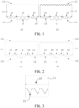
- the back contact solar cell includes: a semiconductor substrate 11, a first doped semiconductor layer 16, and a second doped semiconductor layer 17.
- the semiconductor substrate 11 has a first surface 111 and a second surface 112 opposite to the first surface.
- the second surface 112 includes a first region 12 and a second region 13 arranged alternately in a direction parallel to the second surface 112.
- a surface of the first region 12 has a first convex structure 14, and a surface of the second region 13 has a second convex structure 15.
- a morphology of each convex distributed in the first convex structure 14 is different from a morphology of each convex distributed in the second convex structure 15.
- the first doped semiconductor layer 16 is formed in or on the first region 12; and the second doped semiconductor layer 17 is formed in or on the second region 13.
- a conductivity type of the second doped semiconductor layer 17 is opposite to a conductivity type of the first doped semiconductor layer 16.
- the semiconductor substrate may be a substrate made of a semiconductor material such as a silicon substrate, a silicon germanium substrate, or a germanium substrate.
- the semiconductor substrate may be an N-type semiconductor substrate or a P-type semiconductor substrate.
- the first surface of the semiconductor substrate corresponds to a light receiving surface of the back contact solar cell; and the second surface of the semiconductor substrate corresponds to a back surface of the back contact solar cell.
- the first surface 111 of the semiconductor substrate 11 may be a polished surface, that is, a flat surface.
- the first surface 111 of the semiconductor substrate 11 may alternatively be a textured structure with a morphology such as a regular pyramid.
- the textured structure has a light trapping function, so that when the first surface 111 of the semiconductor substrate 11 has the textured structure, more light can be refracted into the semiconductor substrate 11, thereby improving the photoelectric conversion efficiency of the back contact solar cell.
- the semiconductor substrate 11 may only include the first region 12 and the second region 13 arranged alternately. It should be understood that, a boundary between the first region 12 and the second region 13 is a virtual boundary.
- a position, quantity, and size of the first region 12 on the semiconductor substrate 11 affect a position, quantity, and size of the subsequently formed first doped semiconductor layer.
- the second doped semiconductor layer is formed in or on the second region 13, a position, quantity, and size of the second region 13 on the semiconductor substrate 11 affect a position, quantity, and size of the subsequently formed second doped semiconductor layer.
- positions, quantities, and sizes of the first region 12 and the second region 13 on the semiconductor substrate 11 may be set according to a requirement on information such as positions of the first doped semiconductor layer and the second doped semiconductor layer in an actual application scenario, and are not specifically limited herein.
- a morphology of each convex distributed in the first convex structure is different from a morphology of each convex distributed in the second convex structure may refer to that: a shape of a surface of each convex distributed in the first convex structure facing away from the semiconductor substrate is different from a shape of a surface of each convex distributed in the second convex structure facing away from the semiconductor substrate; and/or a size of each convex distributed in the first convex structure is different from a size of each convex distributed in the second convex structure.
- the shape of the surface of each of the convexs distributed in the first convex structure and the second convex structure facing away from the semiconductor substrate may be a polygon such as a square, a rectangle, a trapezoid, or a rhombus.
- a specific shape of the surface of each of the convexs distributed in the first convex structure and the second convex structure facing away from the semiconductor substrate may be set according to an actual requirement, and is not specifically limited herein.
- That a size of each convex distributed in the first convex structure is different from a size of each convex distributed in the second convex structure may refer to that: a size of the surface of each convex distributed in the first convex structure facing away from the semiconductor substrate is different from a size of the surface of each convex distributed in the second convex structure facing away from the semiconductor substrate.
- a size of the surface of each convex distributed in the first convex structure facing away from the semiconductor substrate is different from a size of the surface of each convex distributed in the second convex structure facing away from the semiconductor substrate.
- a side length of the first quasi-regular polygon is different from a side length of the second quasi-regular polygon.
- a size of a quasi-regular polygon corresponding to a side of each convex distributed in the first convex structure facing away from the semiconductor substrate is different from a size of a quasi-regular polygon corresponding to a side of each convex distributed in the second convex structure facing away from the semiconductor substrate.
- the specific formation positions of the first doped semiconductor layer and the second doped semiconductor layer may be distinguished from each other more intuitively through at least a size difference obtained by comparing quasi-regular polygons corresponding to the convexs on the surface of the first doped semiconductor layer and the surface of the second doped semiconductor layer.
- the shape of the surface of each of the convexs distributed in the first convex structure and the second convex structure facing away from the semiconductor substrate may alternatively be a non-quasi-regular polygon such as a circle, provided that the morphology of each convex distributed in the first convex structure is different from the morphology of each convex distributed in the second convex structure.
- a height of each convex distributed in the first convex structure is different from a height of each convex distributed in the second convex structure.
- the specific formation positions of the first doped semiconductor layer and the second doped semiconductor layer may be distinguished from each other through at least a difference obtained by comparing the heights corresponding to the convexs on the surface of the first doped semiconductor layer and the surface of the second doped semiconductor layer. Therefore, a possible solution for distinguishing between the first doped semiconductor layer and the second doped semiconductor layer is provided, and the applicability of the back contact solar cell provided in this application in different application scenarios is improved.
- the size of each convex distributed in the first convex structure may be greater than the size of each convex distributed in the second convex structure, or the size of each convex distributed in the first convex structure may be less than the size of each convex distributed in the second convex structure, provided that the sizes of the convexs on the two convex structures are different.
- the second surface 112 may further include an isolation region 18 between each first region 12 and each second region 13 neighboring to the first region.
- a conductivity type of the first doped semiconductor layer formed in or on the first region 12 is opposite to a conductivity type of the second doped semiconductor layer formed in or on the second region 13.
- the isolation region 18 can separate the first doped semiconductor layer and the second doped semiconductor layer adjacent to each other, so that recombination of the carriers having different conductivity types at a lateral junction of the first doped semiconductor layer and the second doped semiconductor layer is suppressed, thereby preventing current leakage at the lateral junction of the two doped semiconductor layers and further improving the photoelectric conversion efficiency of the back contact solar cell.
- a morphology of the isolation region may be set according to an actual application scenario, provided that the morphology of the isolation region can be applied to the back contact solar cell provided in the embodiments of this application.
- a surface of the isolation region may have a regular pyramid textured structure 21, a third pyramid base structure 22, or an inverted pyramid structure 23.
- the surface of the isolation region 18 when the surface of the isolation region 18 has the third pyramid base structure 22, the surface of the isolation region 18 is a flat polished surface.
- the polished surface has a relatively good reflection characteristic, so that light can be at least partially reflected back into the semiconductor substrate 11 after reaching an inner surface of the isolation region 18 and be reused by the semiconductor substrate 11, thereby improving the utilization of light energy by the back contact solar cell.
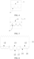
- FIG. 5 when the surface of the isolation region 18 has the inverted pyramid structure 23, a hole of the inverted pyramid structure 23 extends into the semiconductor substrate 11.
- the first doped semiconductor layer and the second doped semiconductor layer may be isolated through a physical isolating material such as air or a passivation material inside the inverted pyramid structure 23, thereby further reducing recombination rates of carriers having opposite conductivity types at the lateral junction of the first doped semiconductor layer and the second doped semiconductor layer, and improving the photoelectric conversion efficiency of the back contact solar cell.
- a physical isolating material such as air or a passivation material inside the inverted pyramid structure 23
- FIG. 3 when the surface of the isolation region 18 has the regular pyramid textured structure 21, because the regular pyramid textured structure 21 has a light trapping characteristic, more light can be refracted from an outer surface of the isolation region 18 into the semiconductor substrate 11, thereby improving the photoelectric conversion efficiency of the back contact solar cell.
- a size of each convex distributed in the third pyramid base structure may be the same as or different from the size of each convex distributed in the first convex structure or the second convex structure.
- the size of each convex distributed in the third pyramid base structure may be the same as the size of each convex distributed in the first convex structure or the second convex structure. In this case, positions of the three regions may be distinguished from each other through height differences between the surfaces of the three regions.
- the size of each convex distributed in the third pyramid base structure is different from the size of each convex distributed in the convex structure corresponding to the region flush with the isolation region, so that the positions of the three regions can be distinguished from each other through the sizes of the convexs.
- the size and the shape of the isolation region affect a gap between the first doped semiconductor layer and the second doped semiconductor layer, so that a width of the isolation region may be set according to a requirement on the gap between the first doped semiconductor layer and the second doped semiconductor layer in an actual application scenario.
- the width of the isolation region may range from 10 ⁇ m to 400 ⁇ m.
- the specific formation positions, conductivity types, and doping concentrations of the first doped semiconductor layer and the second doped semiconductor layer may be set according to an actual requirement, provided that the first doped semiconductor layer and the second doped semiconductor layer can be applied to the back contact solar cell provided in the embodiments of this application.
- the first doped semiconductor layer 16 may be formed in the first region 12, and the second doped semiconductor layer 17 is formed in the second region 13.
- the semiconductor substrate 11 only includes the first region 12 and the second region 13
- at least one of the first doped semiconductor layer 16 and the second doped semiconductor layer 17 may be only partially formed in the corresponding region, to suppress recombination of carriers having opposite conductivity types at a junction of the two doped semiconductor layers.
- the semiconductor substrate 11 further includes the isolation region 18, at least one of the first doped semiconductor layer 16 and the second doped semiconductor layer 17 may fill up the corresponding region.
- the first doped semiconductor layer may be an N-type semiconductor layer doped with N-type conductive particles such as phosphorus.
- the second doped semiconductor layer may be a P-type semiconductor layer doped with P-type conductive particles such as boron.
- the first doped semiconductor layer is a P-type semiconductor layer.
- the second doped semiconductor layer is an N-type semiconductor layer.
- the doping concentration of the first doped semiconductor layer may be the same as the doping concentration of the second doped semiconductor layer. Alternatively, the doping concentration of the first doped semiconductor layer may be less than the doping concentration of the second doped semiconductor layer. Alternatively, the doping concentration of the first doped semiconductor layer may be greater than the doping concentration of the second doped semiconductor layer.
- the first doped semiconductor layer when the first doped semiconductor layer is formed on the first region, in terms of internal arrangement of substances, the first doped semiconductor layer may be an amorphous semiconductor layer, a microcrystalline semiconductor layer, a monocrystalline semiconductor layer, a polycrystalline semiconductor layer, a nanocrystalline semiconductor layer, or the like.
- a material of the first doped semiconductor layer may include a semiconductor material such as silicon, silicon germanium, germanium, doped silicon carbide, or gallium arsenide.
- the first doped semiconductor layer In terms of passivation, the first doped semiconductor layer may be a hydrogenated doped layer.
- the first doped semiconductor layer laterally intersects with the second doped semiconductor layer, so the first doped semiconductor layer is preferably made of a semiconductor material whose lateral conductivity is zero.
- the first doped semiconductor layer may be made of a material such as monocrystalline silicon or polycrystalline silicon which has a specific lateral conductivity, and the lateral conductivity of the first doped semiconductor layer can be reduced by setting a thickness of the first doped semiconductor layer to a suitable range, thereby suppressing recombination of carriers at the lateral junction of the first doped semiconductor layer and the second doped semiconductor layer.
- the thickness of the first doped semiconductor layer and a thickness of the second doped semiconductor layer may be set according to an actual application scenario, and are not specifically limited herein.
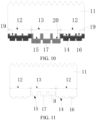
- the surface of the first region 12 on the second surface has the first convex structure 14; and the surface of the second region 13 on the second surface has the second convex structure 15.
- the morphology of each convex distributed in the first convex structure 14 is different from the morphology of each convex distributed in the second convex structure 15. In this case, as shown in FIG.
- the morphology of the side of the first doped semiconductor layer 16 facing away from the semiconductor substrate 11 is also different from the morphology of the side of the second doped semiconductor layer 17 facing away from the semiconductor substrate 11, so that specific formation positions of the first doped semiconductor layer 16 and the second doped semiconductor layer 17 on the semiconductor substrate 11 can be well distinguished from each other through the difference.
- the back contact solar cell may further include a surface passivation layer 24 covering the first doped semiconductor layer 16 and the second doped semiconductor layer 17.
- the surface passivation layer 24 can passivate a side of the back contact solar cell located on the second surface, thereby reducing a carrier recombination rate on the second surface and improving the photoelectric conversion efficiency of the back contact solar cell.
- a material and a thickness of the surface passivation layer may be set according to an actual requirement, and are not specifically limited herein.
- the material of the surface passivation layer may be one or more of silicon nitride, silicon oxide, silicon oxynitride, aluminum oxide, silicon carbide, or amorphous silicon.
- the back contact solar cell may further include a first electrode 25 formed on the first doped semiconductor layer 16, to lead out carriers collected by the first doped semiconductor layer 16 through the first electrode 25.
- a material of the first electrode may be a conductive material such as silver, aluminum, gallium, stibium, copper, or nickel.
- a specific material of the first electrode 25 may be determined according to the conductivity type of the first doped semiconductor layer 16. For example, when the first doped semiconductor layer 16 is a P-type doped semiconductor layer, the material of the first electrode 25 may be aluminum or gallium. In another example, when the first doped semiconductor layer 16 is an N-type doped semiconductor layer, the material of the first electrode 25 may be stibium.
- material elements in the first electrode 25 may be diffused as doping elements into the first doped semiconductor layer 16 through sintering, to increase the doping concentration of the first doped semiconductor layer 16, reduce contact resistance between the first doped semiconductor layer 16 and the first electrode 25, and improve an open circuit voltage of the back contact solar cell.
- the back contact solar cell may further include a second electrode 26 formed on the second doped semiconductor layer 17, to lead out carriers collected by the second doped semiconductor layer 17 through the second electrode 26.
- a second electrode 26 formed on the second doped semiconductor layer 17, to lead out carriers collected by the second doped semiconductor layer 17 through the second electrode 26.
- a material of the second electrode 26 reference may be made to the material of the first electrode 25 described above, and details are not described herein again.
- the back contact solar cell compared with existing back contact solar cells including two types of doped semiconductor layers having opposite conductivity types and a same morphology, in the back contact solar cell provided in this application, there is higher distinguishability between the first doped semiconductor layer and the second doped semiconductor layer, so that the difficulty in accurately arranging the conductive structures having the same polarities as the two types of doped semiconductor layers on the first doped semiconductor layer and the second doped semiconductor layer respectively can be reduced, and a risk of short circuit of the back contact solar cell caused by coupling of the first doped semiconductor layer and the second doped semiconductor layer having opposite conductivity types through the conductive structures can be further reduced, thereby improving the electrical stability of the back contact solar cell.
- surfaces of both the first convex structure and the second convex structure are smoother than a surface of a textured structure. Therefore, compared with back contact solar cells with the textured structure on a back surface, in the back contact solar cell provided in this application, surfaces of the first doped semiconductor layer and the second doped semiconductor layer are smoother, facilitating deposition of a surface passivation layer on the surfaces of the two doped semiconductor layers. Therefore, the surface passivation layer forms a denser film with an improved passivation effect, thereby effectively improving an open circuit voltage of the back contact solar cell and improving the photoelectric conversion efficiency of the back contact solar cell.
- the first convex structure may be a macrostructure arranged on the surface of the first region or may be a microstructure arranged on the surface of the first region.
- the surface of the first region 12 may be provided with first grid-shaped grooves recessed toward the semiconductor substrate 11; and the first convex structure 14 is located in a grid region encircled by the first grid-shaped grooves.
- the first grid-shaped grooves recessed toward the semiconductor substrate 11 may be provided through manners such as laser etching on the first region, so that a part of the first region located on inner sides of the first grid-shaped grooves forms the first convex structure 14.
- each convex distributed in the first convex structure 14 is obvious, helping distinguish a specific formation position of the first doped semiconductor layer through the first convex structure 14.
- a width and a depth of each of the first grid-shaped grooves may be determined according to a requirement on the size of the first region 12 and the side length and the height of each convex distributed in the first convex structure 14, and are not specifically limited herein.
- the first convex structure when the first convex structure is a microstructure, the first convex structure may be a first pyramid base structure obtained through polishing treatment.
- the first convex structure may be obtained by performing polishing treatment on a regular pyramid structure originally formed on the surface of the first region and removing an upper half part of the regular pyramid structure, to obtain the first pyramid base structure.
- the first pyramid base structure is a microstructure.
- the first convex structure is the first pyramid base structure obtained through polishing treatment
- thinning to a thickness of the semiconductor substrate for forming the first convex structure on the surface of the first region may be reduced, so that a probability that light is absorbed after being incident to the semiconductor substrate is further increased while production of a thin back contact solar cell is implemented, thereby improving the photoelectric conversion efficiency of the back contact solar cell.
- the second convex structure may be a macrostructure arranged on the surface of the second region or may be a microstructure arranged on the surface of the second region.
- the surface of the second region 13 may be provided with second grid-shaped grooves recessed toward the semiconductor substrate 11; and the second convex structure 15 is located in a grid region encircled by the second grid-shaped grooves.
- a width and a depth of each of the second grid-shaped grooves may be determined according to a requirement on the size of the second region 13 and the side length and the height of each convex distributed in the second convex structure 15, and are not specifically limited herein.
- the second convex structure when the second convex structure is a microstructure, the second convex structure may be a second pyramid base structure obtained through polishing treatment.
- the second convex structure may be a second pyramid base structure obtained through polishing treatment.
- the side length of the first quasi-regular polygon is less than the side length of the second quasi-regular polygon.
- the height of each convex distributed in the first convex structure 14 is greater than the height of each convex distributed in the second convex structure 15.
- a region corresponding to a smaller quasi-regular polygon is the formation position of the first doped semiconductor layer 16; and a region corresponding to a larger quasi-regular polygon is the formation position of the second doped semiconductor layer 17.
- the surface of the second region 13 having the second convex structure 15 is smoother than the surface of the first region 12 having the first convex structure 14, so that a passivation effect of the surface passivation layer to a surface of the second doped semiconductor layer 17 can be enhanced, thereby further improving the photoelectric conversion efficiency of the back contact solar cell.
- a region corresponding to a greater convex height is the formation position of the first doped semiconductor layer 16; and a region corresponding to a smaller convex height is the formation position of the second doped semiconductor layer 17, so that the first doped semiconductor layer 16 and the second doped semiconductor layer 17 can be distinguished from each other easily.
- first convex structure 14 and the second convex structure 15 are respectively the first pyramid base structure and the second pyramid base structure obtained through polishing treatment
- a height is inversely proportional to a side length of each of the first pyramid base structure and the second pyramid base structure
- the side length of the first quasi-regular polygon is less than the side length of the second quasi-regular polygon.
- the side length of the second quasi-regular polygon may alternatively be less than the side length of the first quasi-regular polygon.
- specific values of the side length of the first quasi-regular polygon and the side length of the second quasi-regular polygon may be set according to an actual requirement, and are not specifically limited herein.
- the height of each convex distributed in the second convex structure may be less than the height of each convex distributed in the first convex structure.
- Specific values of the heights of the convexs distributed in the first convex structure and the second convex structure may be set according to an actual requirement, and are not specifically limited herein.
- the side length of the first quasi-regular polygon may range from 0.5 ⁇ m to 20 ⁇ m; and the height of each convex distributed in the first convex structure ranges from 0.5 ⁇ m to 5 ⁇ m.
- the side length of the first quasi-regular polygon has a specific optional range, so that there is no need to impose a strict requirement on treatment conditions such as a polishing time to process a side length of each convex on the surface of the first region to a fixed value, thereby reducing the difficulty of the treatment such as polishing.
- the first quasi-regular polygon has a micron-sized side length, so that the morphology of the first region is more obvious, and the specific formation positions of the first doped semiconductor layer and the second doped semiconductor layer can be distinguished from each other more easily.
- beneficial effects of setting the height of each convex distributed in the first convex structure to 0.5 ⁇ m to 5 ⁇ m reference may be made to the beneficial effects when the side length of each convex distributed in the first convex structure ranges from 0.5 ⁇ m to 20 ⁇ m described above, and details are not described herein again.
- the side length of each convex distributed in the second convex structure ranges from 10 ⁇ m to 50 ⁇ m; and the height of each convex distributed in the second convex structure ranges from 0.5 ⁇ m to 10 ⁇ m.
- a thickness of the second doped semiconductor layer generally ranges from 20 nm to 600 nm.
- the side length of each convex on the second region ranges from 10 ⁇ m to 50 ⁇ m, and the side length is far greater than the thickness of the second doped semiconductor layer.
- the surface of the second doped semiconductor layer facing away from the semiconductor substrate has an obvious convex morphology, helping improve the distinguishability of the formation position of the second doped semiconductor layer.
- the doping concentration of the first doped semiconductor layer 16 is less than the doping concentration of the second doped semiconductor layer 17.
- contact resistance between a doped semiconductor layer and a conductive structure is inversely proportional to a doping concentration of the doped semiconductor layer.
- the side length of the second quasi-regular polygon is greater than the side length of the first quasi-regular polygon, the surface of the second region having the second convex structure is smoother than the surface of the first region having the first convex structure, so that the surface of the second doped semiconductor layer is smoother than the surface of the first doped semiconductor layer.
- a smooth surface corresponds to a small specific surface area.
- a thickness of the passivation material on the second doped semiconductor layer is greater than a thickness of the passivation material on the first doped semiconductor layer.
- a thickness of the surface passivation layer 24 on the second doped semiconductor layer 17 with a greater doping concentration is greater than a thickness of the surface passivation layer on the first doped semiconductor layer 16 with a smaller doping concentration.
- the thickness of the surface passivation layer 24 on the second doped semiconductor layer 17 is large, so that a problem that a part of the surface passivation layer 24 on the second doped semiconductor layer 17 is prematurely burnt through due to a long sintering time or a high sintering temperature can be resolved, thereby ensuring good contact of the first doped semiconductor layer 16 and the second doped semiconductor layer 17 and improving the electrical performance of the back contact solar cell.
- the doping concentration of the first doped semiconductor layer is greater than the doping concentration of the second doped semiconductor layer, and the foregoing effects can also be achieved.
- the first convex structure and the second convex structure are respectively the first pyramid base structure and the second pyramid base structure obtained through polishing treatment
- the height is inversely proportional to the side length of each of the first pyramid base structure and the second pyramid base structure, in a case that the height of each convex distributed in the first convex structure is greater than the height of each convex distributed in the second convex structure; or in a case that the side length of the first quasi-regular polygon is less than the side length of the second quasi-regular polygon and the height of each convex distributed in the first convex structure is greater than the height of each convex distributed in the second convex structure, by setting the doping concentration of the first doped semiconductor layer to be less than the doping concentration of the second doped semiconductor layer, the foregoing beneficial effects can also be achieved.
- the first convex structure and the second convex structure are respectively the first pyramid base structure and the second pyramid base structure obtained through polishing treatment
- the height of each convex distributed in the first convex structure is greater than the height of each convex distributed in the second convex structure
- the side length of the first quasi-regular polygon is greater than the side length of the second quasi-regular polygon and the height of each convex distributed in the first convex structure is less than the height of each convex distributed in the second convex structure
- a doping concentration difference between the two doped semiconductor layers may be determined according to a doping process.
- the doping concentration of the first doped semiconductor layer may range from 10 18 cm -3 to 10 20 cm -3
- the doping concentration of the second doped semiconductor layer may range from 10 17 cm -3 to 10 19 cm -3 .
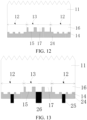
- the first convex structure 14 and the second convex structure 15 each include a top surface and a bottom surface opposite to the top surface; and a surface of each of the first convex structure 14 and the second convex structure 15 facing away from the semiconductor substrate 11 is defined as the top surface.
- the top surface of the second convex structure 15 is recessed toward the semiconductor substrate 11 relative to the top surface of the first convex structure 14.
- the top surface of the second convex structure 15 is recessed toward the semiconductor substrate 11 relative to the top surface of the first convex structure 14.
- the surface of the first convex structure 14 facing away from the semiconductor substrate 11 is higher than the surface of the second convex structure 15 facing away from the semiconductor substrate 11 by a height H, so that the surface of the second doped semiconductor layer 17 facing away from the semiconductor substrate 11 is also recessed inward toward the semiconductor substrate 11 relative to a surface of the first doped semiconductor layer 16 facing away from the semiconductor substrate 11.
- a height difference between surfaces of parts of the surface passivation layer 24 on the first region 12 and the second region 13 can also be eliminated by recessing the surface of the second doped semiconductor layer 17 facing away from the semiconductor substrate 11 inward toward the semiconductor substrate 11 relative to the surface of the first doped semiconductor layer 16 facing away from the semiconductor substrate 11.
- the first electrode 25 and the second electrode 26 subsequently formed may respectively run through the surface passivation layer 24 through corresponding types of electrode windows, thereby reducing contact resistance at the first electrode 25 and the second electrode 26.
- the first electrode 25 and the second electrode 26 subsequently formed do not extend into doped semiconductor layers having corresponding conductivity types, thereby ensuring that carrier recombination rates at both the first electrode 25 and the second electrode 26 are low and improving the photoelectric conversion efficiency of the back contact solar cell.
- the top surface of the first convex structure is recessed toward the semiconductor substrate relative to the top surface of the second convex structure, and the foregoing effect can also be achieved.
- the first convex structure and the second convex structure are respectively the first pyramid base structure and the second pyramid base structure obtained through polishing treatment
- the height is inversely proportional to the side length of each of the first pyramid base structure and the second pyramid base structure
- the height of each convex distributed in the first convex structure is greater than the height of each convex distributed in the second convex structure
- the side length of the first quasi-regular polygon is less than the side length of the second quasi-regular polygon and the height of each convex distributed in the first convex structure is greater than the height of each convex distributed in the second convex structure
- the top surface of the second convex structure is recessed toward the semiconductor substrate relative to the top surface of the first convex structure, and the foregoing effect can also be achieved.
- the first convex structure and the second convex structure are respectively the first pyramid base structure and the second pyramid base structure obtained through polishing treatment
- the height of each convex distributed in the first convex structure is less than the height of each convex distributed in the second convex structure
- the side length of the first quasi-regular polygon is greater than the side length of the second quasi-regular polygon and the height of each convex distributed in the first convex structure is less than the height of each convex distributed in the second convex structure
- the top surface of the first convex structure is recessed toward the semiconductor substrate relative to the top surface of the second convex structure, and the foregoing effects can also be achieved.
- a height difference between the top surface of the first convex structure and the top surface of the second convex structure may be determined according to a difference between thicknesses of the surface passivation layer on the two convex structures, and is not specifically limited herein.
- the height difference between the top surface of the first convex structure and the top surface of the second convex structure may range from 0.5 ⁇ m to 20 ⁇ m.
- each convex distributed in the first convex structure and each convex distributed in the second convex structure both include a top surface and a bottom surface opposite to the top surface.
- a surface of each convex distributed in the first convex structure and each convex distributed in the second convex structure facing away from the semiconductor substrate is defined as the top surface.
- an area of the top surface of each convex distributed in the first convex structure is less than an area of the bottom surface of the convex; and an area of the top surface of each convex distributed in the second convex structure is less than an area of the bottom surface of the convex.
- a difference between the area of the top surface and the area of the bottom surface of each of the convexs distributed in the first convex structure and the second convex structure may be set according to an actual requirement, and is not specifically limited herein. It may be understood that, in a case that other factors are the same, a smaller difference between an area of a top surface and an area of a bottom surface of a convex indicates a smoother surface of a region on which the convex is formed, helping improve a passivation effect of the surface passivation layer to the surface of the region.
- a shape of each of the top surface and the bottom surface of each of the convexs distributed in the first convex structure and the second convex structure may be a quasi-regular polygon such as a regular triangle, a square, or a rhombus, or may be a non-quasi-regular polygon such as a circle or an ellipse.
- the shape of the top surface and the shape of the bottom surface of each convex distributed in the first convex structure may be the same or may be different; and the shape of the top surface and the shape of the bottom surface of each convex distributed in the second convex structure may be the same or may be different.
- each convex distributed in the first convex structure and each convex distributed in the second convex structure both have a regular quasi-prism morphology.
- surfaces of the first region and the second region having convexs with the regular quasi-prism morphology are flatter, helping improve the compactness of the parts of the surface passivation layer formed on the first region and the second region, thereby improving a passivation effect of the surface passivation layer to the two regions and further improving the photoelectric conversion efficiency of the back contact solar cell.
- the back contact solar cell when the first doped semiconductor layer 16 is formed on the first region 12, the back contact solar cell further includes a first tunneling passivation layer 19 located between the first convex structure 14 and the first doped semiconductor layer 16.
- the first tunneling passivation layer 19 may form a tunneling passivation contact structure with the first doped semiconductor layer 16.
- the first tunneling passivation layer 19 allows most carriers to tunnel into the first doped semiconductor layer 16 and blocks a few carriers from passing through, and the most carriers are transmitted by the second doped semiconductor layer 17 and collected by a corresponding conductive structure. Therefore, recombination rates of carriers having different conductivity types on the surface of the first region 12 are reduced, and excellent interface passivation and selective collection of carriers are implemented, thereby further improving the photoelectric conversion efficiency of the back contact solar cell.
- a material and a thickness of the first tunneling passivation layer may be set according to an actual requirement, and are not specifically limited herein.
- the material of the first tunneling passivation layer may be a material such as silicon oxide, aluminum oxide, titanium oxide, hafnium dioxide, gallium oxide, tantalum pentoxide, niobium pentoxide, silicon nitride, silicon carbonitride, aluminum nitride, titanium nitride, or titanium carbonitride.
- the thickness of the first tunneling passivation layer may range from 0.5 nm to 5 nm.
- the back contact solar cell when the second doped semiconductor layer 17 is formed on the second region 13, the back contact solar cell further includes a second tunneling passivation layer 20 located between the second convex structure 15 and the second doped semiconductor layer.
- the apparatus embodiments described above are merely examples.
- the units described as separate parts may or may not be physically separate, and the parts displayed as units may or may not be physical units, may be located in one position, or may be distributed on a plurality of network units. Some of or all of the modules may be selected according to an actual requirement for achieving the objectives of the solutions of the embodiments. A person of ordinary skill in the art may understand and implement the embodiments without creative efforts.
Landscapes
- Photovoltaic Devices (AREA)
- Electrodes Of Semiconductors (AREA)
Applications Claiming Priority (2)
| Application Number | Priority Date | Filing Date | Title |
|---|---|---|---|
| CN202222209376.6U CN218975458U (zh) | 2022-08-22 | 2022-08-22 | 一种背接触电池 |
| PCT/CN2023/100256 WO2024041120A1 (fr) | 2022-08-22 | 2023-06-14 | Cellule de contact arrière |
Publications (2)
| Publication Number | Publication Date |
|---|---|
| EP4492475A1 true EP4492475A1 (fr) | 2025-01-15 |
| EP4492475A4 EP4492475A4 (fr) | 2025-06-25 |
Family
ID=86163034
Family Applications (1)
| Application Number | Title | Priority Date | Filing Date |
|---|---|---|---|
| EP23856212.8A Pending EP4492475A4 (fr) | 2022-08-22 | 2023-06-14 | Cellule de contact arrière |
Country Status (6)
| Country | Link |
|---|---|
| US (1) | US20240429333A1 (fr) |
| EP (1) | EP4492475A4 (fr) |
| CN (1) | CN218975458U (fr) |
| AU (1) | AU2023328822B2 (fr) |
| DE (1) | DE212023000147U1 (fr) |
| WO (1) | WO2024041120A1 (fr) |
Families Citing this family (8)
| Publication number | Priority date | Publication date | Assignee | Title |
|---|---|---|---|---|
| CN218975458U (zh) * | 2022-08-22 | 2023-05-05 | 泰州隆基乐叶光伏科技有限公司 | 一种背接触电池 |
| CN118053922A (zh) | 2023-12-15 | 2024-05-17 | 浙江晶科能源有限公司 | 太阳能电池及其制备方法、光伏组件 |
| CN119008726A (zh) | 2023-12-15 | 2024-11-22 | 浙江晶科能源有限公司 | 太阳能电池及其制备方法、光伏组件 |
| CN118053927A (zh) | 2023-12-15 | 2024-05-17 | 浙江晶科能源有限公司 | 太阳能电池及其制备方法、光伏组件 |
| CN118053928A (zh) | 2023-12-15 | 2024-05-17 | 浙江晶科能源有限公司 | 太阳能电池及光伏组件 |
| CN118335814A (zh) * | 2024-04-03 | 2024-07-12 | 浙江晶科能源有限公司 | 背接触太阳能电池、光伏组件 |
| CN120076478B (zh) * | 2025-01-24 | 2026-01-30 | 西安隆基乐叶光伏科技有限公司 | 一种背接触电池和光伏组件 |
| CN121728865A (zh) * | 2026-02-26 | 2026-03-24 | 晶科能源(海宁)有限公司 | 背接触太阳能电池、其制备方法、叠层电池和光伏组件 |
Family Cites Families (11)
| Publication number | Priority date | Publication date | Assignee | Title |
|---|---|---|---|---|
| US4689438A (en) * | 1984-10-17 | 1987-08-25 | Sanyo Electric Co., Ltd. | Photovoltaic device |
| US4918030A (en) * | 1989-03-31 | 1990-04-17 | Electric Power Research Institute | Method of forming light-trapping surface for photovoltaic cell and resulting structure |
| JP3764843B2 (ja) * | 2000-06-06 | 2006-04-12 | シャープ株式会社 | 太陽電池セル |
| US20120273036A1 (en) * | 2011-04-29 | 2012-11-01 | Semiconductor Energy Laboratory Co., Ltd. | Photoelectric conversion device and manufacturing method thereof |
| JP5917082B2 (ja) * | 2011-10-20 | 2016-05-11 | 株式会社半導体エネルギー研究所 | 光電変換装置の作製方法 |
| JP5777795B2 (ja) * | 2012-02-24 | 2015-09-09 | 三菱電機株式会社 | 光起電力素子 |
| CN106531816B (zh) * | 2016-12-30 | 2019-02-05 | 中国科学院微电子研究所 | 一种背结背接触太阳能电池 |
| JP7433152B2 (ja) * | 2020-07-13 | 2024-02-19 | 株式会社カネカ | 太陽電池および太陽電池の製造方法 |
| CN113394304B (zh) * | 2021-07-22 | 2025-10-17 | 浙江爱旭太阳能科技有限公司 | 一种太阳能电池及其背面接触结构、电池组件及光伏系统 |
| CN113964216B (zh) * | 2021-09-22 | 2023-10-27 | 泰州隆基乐叶光伏科技有限公司 | 一种背接触电池及其制作方法 |
| CN218975458U (zh) * | 2022-08-22 | 2023-05-05 | 泰州隆基乐叶光伏科技有限公司 | 一种背接触电池 |
-
2022
- 2022-08-22 CN CN202222209376.6U patent/CN218975458U/zh active Active
-
2023
- 2023-06-14 WO PCT/CN2023/100256 patent/WO2024041120A1/fr not_active Ceased
- 2023-06-14 AU AU2023328822A patent/AU2023328822B2/en active Active
- 2023-06-14 EP EP23856212.8A patent/EP4492475A4/fr active Pending
- 2023-06-14 DE DE212023000147.0U patent/DE212023000147U1/de active Active
-
2024
- 2024-09-05 US US18/825,297 patent/US20240429333A1/en active Pending
Also Published As
| Publication number | Publication date |
|---|---|
| AU2023328822B2 (en) | 2026-03-05 |
| DE212023000147U1 (de) | 2024-11-21 |
| AU2023328822A1 (en) | 2025-02-06 |
| EP4492475A4 (fr) | 2025-06-25 |
| CN218975458U (zh) | 2023-05-05 |
| WO2024041120A1 (fr) | 2024-02-29 |
| US20240429333A1 (en) | 2024-12-26 |
Similar Documents
| Publication | Publication Date | Title |
|---|---|---|
| EP4492475A1 (fr) | Cellule de contact arrière | |
| US12490547B2 (en) | Solar cell and photovoltaic module | |
| AU2023278024B2 (en) | Solar cells | |
| EP4290587A1 (fr) | Cellule solaire et module photovoltaïque | |
| US20250176308A1 (en) | Solar cell and manufacturing method therefor | |
| EP4550424A1 (fr) | Cellule solaire | |
| WO2025130118A1 (fr) | Cellule de contact arrière et son procédé de fabrication | |
| JP7639208B1 (ja) | 太陽電池及びその製造方法、積層電池、並びに光起電力モジュール | |
| JP2026501501A (ja) | バックコンタクト電池及びその製造方法 | |
| JP7814575B2 (ja) | 太陽電池及び光起電力モジュール | |
| CN117637891A (zh) | 一种背接触电池及其制造方法、光伏组件和掩膜版 | |
| JP7811293B2 (ja) | バックコンタクト太陽電池、光起電力モジュール | |
| CN222088623U (zh) | 太阳能电池及光伏组件 | |
| CN118553798A (zh) | 一种太阳能电池及其制备方法、光伏组件 | |
| CN118231514A (zh) | 太阳能电池制备方法 | |
| US12278295B1 (en) | Solar cell, method for manufacturing solar cell, and photovoltaic module | |
| CN106206783A (zh) | 太阳能电池、其模组及其制造方法 | |
| US12376415B2 (en) | Solar cell and photovoltaic module | |
| EP4676194A1 (fr) | Cellule solaire et module photovoltaïque | |
| US20250331332A1 (en) | Solar cell and preparation method thereof, photovoltaic module | |
| CN109560146B (zh) | 电池 |
Legal Events
| Date | Code | Title | Description |
|---|---|---|---|
| STAA | Information on the status of an ep patent application or granted ep patent |
Free format text: STATUS: THE INTERNATIONAL PUBLICATION HAS BEEN MADE |
|
| PUAI | Public reference made under article 153(3) epc to a published international application that has entered the european phase |
Free format text: ORIGINAL CODE: 0009012 |
|
| STAA | Information on the status of an ep patent application or granted ep patent |
Free format text: STATUS: REQUEST FOR EXAMINATION WAS MADE |
|
| 17P | Request for examination filed |
Effective date: 20241009 |
|
| AK | Designated contracting states |
Kind code of ref document: A1 Designated state(s): AL AT BE BG CH CY CZ DE DK EE ES FI FR GB GR HR HU IE IS IT LI LT LU LV MC ME MK MT NL NO PL PT RO RS SE SI SK SM TR |
|
| REG | Reference to a national code |
Ref country code: DE Ref legal event code: R079 Free format text: PREVIOUS MAIN CLASS: H01L0031035200 Ipc: H10F0010140000 |
|
| A4 | Supplementary search report drawn up and despatched |
Effective date: 20250527 |
|
| RIC1 | Information provided on ipc code assigned before grant |
Ipc: H10F 77/70 20250101ALI20250521BHEP Ipc: H10F 10/14 20250101AFI20250521BHEP |
|
| DAV | Request for validation of the european patent (deleted) | ||
| DAX | Request for extension of the european patent (deleted) |