EP4492529A2 - Accumulateur pour outils électriques - Google Patents
Accumulateur pour outils électriques Download PDFInfo
- Publication number
- EP4492529A2 EP4492529A2 EP24185867.9A EP24185867A EP4492529A2 EP 4492529 A2 EP4492529 A2 EP 4492529A2 EP 24185867 A EP24185867 A EP 24185867A EP 4492529 A2 EP4492529 A2 EP 4492529A2
- Authority
- EP
- European Patent Office
- Prior art keywords
- accumulator
- wet space
- housing
- interior
- sealing
- Prior art date
- Legal status (The legal status is an assumption and is not a legal conclusion. Google has not performed a legal analysis and makes no representation as to the accuracy of the status listed.)
- Pending
Links
Images




Classifications
-
- H—ELECTRICITY
- H01—ELECTRIC ELEMENTS
- H01M—PROCESSES OR MEANS, e.g. BATTERIES, FOR THE DIRECT CONVERSION OF CHEMICAL ENERGY INTO ELECTRICAL ENERGY
- H01M10/00—Secondary cells; Manufacture thereof
- H01M10/42—Methods or arrangements for servicing or maintenance of secondary cells or secondary half-cells
- H01M10/425—Structural combination with electronic components, e.g. electronic circuits integrated to the outside of the casing
- H01M10/4257—Smart batteries, e.g. electronic circuits inside the housing of the cells or batteries
-
- H—ELECTRICITY
- H01—ELECTRIC ELEMENTS
- H01M—PROCESSES OR MEANS, e.g. BATTERIES, FOR THE DIRECT CONVERSION OF CHEMICAL ENERGY INTO ELECTRICAL ENERGY
- H01M10/00—Secondary cells; Manufacture thereof
- H01M10/42—Methods or arrangements for servicing or maintenance of secondary cells or secondary half-cells
- H01M10/425—Structural combination with electronic components, e.g. electronic circuits integrated to the outside of the casing
-
- H—ELECTRICITY
- H01—ELECTRIC ELEMENTS
- H01M—PROCESSES OR MEANS, e.g. BATTERIES, FOR THE DIRECT CONVERSION OF CHEMICAL ENERGY INTO ELECTRICAL ENERGY
- H01M10/00—Secondary cells; Manufacture thereof
- H01M10/42—Methods or arrangements for servicing or maintenance of secondary cells or secondary half-cells
- H01M10/48—Accumulators combined with arrangements for measuring, testing or indicating the condition of cells, e.g. the level or density of the electrolyte
- H01M10/482—Accumulators combined with arrangements for measuring, testing or indicating the condition of cells, e.g. the level or density of the electrolyte for several batteries or cells simultaneously or sequentially
-
- H—ELECTRICITY
- H01—ELECTRIC ELEMENTS
- H01M—PROCESSES OR MEANS, e.g. BATTERIES, FOR THE DIRECT CONVERSION OF CHEMICAL ENERGY INTO ELECTRICAL ENERGY
- H01M50/00—Constructional details or processes of manufacture of the non-active parts of electrochemical cells other than fuel cells, e.g. hybrid cells
- H01M50/20—Mountings; Secondary casings or frames; Racks, modules or packs; Suspension devices; Shock absorbers; Transport or carrying devices; Holders
- H01M50/233—Mountings; Secondary casings or frames; Racks, modules or packs; Suspension devices; Shock absorbers; Transport or carrying devices; Holders characterised by physical properties of casings or racks, e.g. dimensions
- H01M50/24—Mountings; Secondary casings or frames; Racks, modules or packs; Suspension devices; Shock absorbers; Transport or carrying devices; Holders characterised by physical properties of casings or racks, e.g. dimensions adapted for protecting batteries from their environment, e.g. from corrosion
-
- H—ELECTRICITY
- H01—ELECTRIC ELEMENTS
- H01M—PROCESSES OR MEANS, e.g. BATTERIES, FOR THE DIRECT CONVERSION OF CHEMICAL ENERGY INTO ELECTRICAL ENERGY
- H01M50/00—Constructional details or processes of manufacture of the non-active parts of electrochemical cells other than fuel cells, e.g. hybrid cells
- H01M50/20—Mountings; Secondary casings or frames; Racks, modules or packs; Suspension devices; Shock absorbers; Transport or carrying devices; Holders
- H01M50/247—Mountings; Secondary casings or frames; Racks, modules or packs; Suspension devices; Shock absorbers; Transport or carrying devices; Holders specially adapted for portable devices, e.g. mobile phones, computers, hand tools or pacemakers
-
- H—ELECTRICITY
- H01—ELECTRIC ELEMENTS
- H01M—PROCESSES OR MEANS, e.g. BATTERIES, FOR THE DIRECT CONVERSION OF CHEMICAL ENERGY INTO ELECTRICAL ENERGY
- H01M50/00—Constructional details or processes of manufacture of the non-active parts of electrochemical cells other than fuel cells, e.g. hybrid cells
- H01M50/20—Mountings; Secondary casings or frames; Racks, modules or packs; Suspension devices; Shock absorbers; Transport or carrying devices; Holders
- H01M50/262—Mountings; Secondary casings or frames; Racks, modules or packs; Suspension devices; Shock absorbers; Transport or carrying devices; Holders with fastening means, e.g. locks
-
- H—ELECTRICITY
- H01—ELECTRIC ELEMENTS
- H01M—PROCESSES OR MEANS, e.g. BATTERIES, FOR THE DIRECT CONVERSION OF CHEMICAL ENERGY INTO ELECTRICAL ENERGY
- H01M10/00—Secondary cells; Manufacture thereof
- H01M10/42—Methods or arrangements for servicing or maintenance of secondary cells or secondary half-cells
- H01M10/4207—Methods or arrangements for servicing or maintenance of secondary cells or secondary half-cells for several batteries or cells simultaneously or sequentially
-
- H—ELECTRICITY
- H01—ELECTRIC ELEMENTS
- H01M—PROCESSES OR MEANS, e.g. BATTERIES, FOR THE DIRECT CONVERSION OF CHEMICAL ENERGY INTO ELECTRICAL ENERGY
- H01M10/00—Secondary cells; Manufacture thereof
- H01M10/42—Methods or arrangements for servicing or maintenance of secondary cells or secondary half-cells
- H01M10/425—Structural combination with electronic components, e.g. electronic circuits integrated to the outside of the casing
- H01M2010/4278—Systems for data transfer from batteries, e.g. transfer of battery parameters to a controller, data transferred between battery controller and main controller
-
- H—ELECTRICITY
- H01—ELECTRIC ELEMENTS
- H01M—PROCESSES OR MEANS, e.g. BATTERIES, FOR THE DIRECT CONVERSION OF CHEMICAL ENERGY INTO ELECTRICAL ENERGY
- H01M2220/00—Batteries for particular applications
- H01M2220/30—Batteries in portable systems, e.g. mobile phone, laptop
-
- H—ELECTRICITY
- H01—ELECTRIC ELEMENTS
- H01M—PROCESSES OR MEANS, e.g. BATTERIES, FOR THE DIRECT CONVERSION OF CHEMICAL ENERGY INTO ELECTRICAL ENERGY
- H01M50/00—Constructional details or processes of manufacture of the non-active parts of electrochemical cells other than fuel cells, e.g. hybrid cells
- H01M50/20—Mountings; Secondary casings or frames; Racks, modules or packs; Suspension devices; Shock absorbers; Transport or carrying devices; Holders
- H01M50/284—Mountings; Secondary casings or frames; Racks, modules or packs; Suspension devices; Shock absorbers; Transport or carrying devices; Holders with incorporated circuit boards, e.g. printed circuit boards [PCB]
Definitions
- the present invention relates to an accumulator, in particular a work tool accumulator, for work tools with a housing that surrounds an interior, with at least one energy storage unit arranged in the interior, with a contacting device by means of which an electrical connection can be formed between the energy storage unit and the work tool, and with a locking mechanism by means of which the accumulator can be detachably connected to the work tool.
- the object of the present invention is to create a structurally simple battery that is waterproof.
- the battery can be a work equipment battery.
- the battery can also be abbreviated to battery in the following.
- the battery includes a housing that surrounds an interior space.
- the battery has at least one energy storage unit arranged in the interior.
- the working device can be supplied with electrical energy using the energy storage unit.
- the battery comprises a contacting device by means of which an electrical connection is established between the energy storage unit and the This can be used to supply electrical energy to the work tool. It can also be used to connect the battery to a charger so that the battery can be charged.
- the battery has a locking mechanism by means of which the battery can be detachably connected to the working device.
- the battery also includes a humidity sensor for detecting humidity in the first wet room, in the second wet room, in the interior and/or in the area of the contact device. Humidity or water can be detected using the at least one humidity sensor. This can protect the battery from damage. If humidity is detected, the battery can be switched off, preventing a short circuit, for example.
- At least one wet space is arranged in the housing, wherein the locking mechanism and/or at least partially the contacting device is arranged at least partially in the wet space.
- the accumulator also comprises at least one sealing device that seals the interior against the at least one wet space in a watertight manner. If water gets into the wet space, the sealing device can be used to prevent the water from getting further into the interior and in particular to the energy storage unit and to the control and/or regulating electronics of the accumulator.
- the accumulator has a first and a second wet space, wherein the locking mechanism is at least partially arranged in the first wet space and the contacting device is at least partially arranged in the second wet space.
- the accumulator comprises at least one separating device which separates the interior from at least one wet space.
- the separating device can have the shape of a tub so that water can be collected and it can be prevented that the water gets into the interior.
- the accumulator comprises a first separating device for the first wet space and a second separating device for the second wet space.
- the housing comprises an upper housing shell and a lower housing shell that are connected to one another in a watertight manner.
- a sealing arrangement in particular a sealing element, can be arranged between the upper housing shell and the lower housing shell, so that the interior is sealed.
- the upper housing shell and the lower housing shell can be connected to one another by means of at least one connecting element and/or fastening element.
- the upper housing shell and the lower housing shell can be connected to one another in a form-fitting, force-fitting and/or material-fitting manner.
- the upper housing shell and the lower housing shell are clipped together.
- corresponding clip elements engage in corresponding grooves and/or recesses.
- the upper housing shell and the lower housing shell can also be screwed together using at least one screw. By clipping and/or screwing, the upper housing shell and the lower housing shell can also be separated from one another again, for example to replace the energy storage unit or to repair the battery.
- the at least one wet space in particular the first and/or the second wet space, is located between the housing, in particular the housing upper shell, and the at least one separating device, in particular the first and/or the second separating device.
- the locking mechanism has at least one locking element by means of which the battery can be locked to the working device.
- the locking mechanism has at least one actuating element by means of which the locking element can be actuated so that the accumulator can be released from the working device.
- the locking mechanism in particular the locking element and/or the actuating element, is designed in such a way that water can escape from the wet space past it.
- the locking mechanism can be moved from a locking position to an unlocking position. In the locking position, the battery is locked to the tool. In the unlocking position, the battery can be detached from the tool.
- the actuating element can be actuated or pressed to move the locking mechanism from the locking position to the unlocking position.
- the locking element can have the locking position and the unlocking position and/or can be moved between both positions. When the actuating element is actuated, the locking element can be moved from the locking position to the unlocking position.
- the locking element and/or the actuating element In the locking position, the locking element and/or the actuating element can, for example, close the wet space.
- the locking element and/or the actuating element can close corresponding openings, whereby these openings are explained below.
- the unlocking position the locking element and/or the actuating element can open the wet room, so that the water can flow out of the wet room past the locking element and/or the actuating element.
- the locking element and/or the actuating element can release the corresponding openings in the unlocked position so that the water can escape through the openings.
- At least one display unit is arranged in the, preferably first, wet room, by means of which a charge state of the energy storage unit can be displayed.
- a switch is arranged in the, preferably first, wet room, by means of which the display unit can be activated.
- the housing in particular the housing upper shell, has at least one opening through which the locking element, the actuating element, the display unit, contact elements of the contacting device, the contacting device and/or the switch are guided from the at least one wet space to an outside of the housing.
- the locking element, the actuating element, the display unit and/or the switch at least partially closes the opening.
- the sealing device is arranged in an edge region of the separating device.
- the sealing device is arranged between the separating device and the housing, in particular the housing upper shell, and/or if the at least one sealing device surrounds the at least one opening.
- the sealing device comprises a sealing groove and a sealing element arranged in the sealing groove, wherein the sealing element is preferably a sealing compound, in particular a foam bead.
- the water can escape from the wet space between the locking element, actuating element, display unit and/or switch and the housing, in particular the upper housing shell, in particular through the opening.
- the water can thereby be led out of the wet space, for example by simply actuating the actuating element.
- the isolating device has a switch cover so that the switch is watertight sealed against the wet room.
- the separating device has a display cover so that the display unit is watertight against the wet room.
- the humidity sensor comprises a sensor element which is arranged in the first wet room, in the second wet room, in the interior and/or in the area of the contacting device.
- the sensor element can be, for example, a sensor which is arranged in the first wet room, in the second wet room, in the interior and/or in the area of the contacting device or which extends into at least one of the spaces mentioned. Additionally or alternatively, the sensor element can also be a contact element of the contacting device. With the help of the Contact element of the contacting device can determine the humidity by means of a potential shift.
- the humidity sensor is arranged in the second wet room and/or in the area of the contacting device, since the contact elements to which an electrical voltage is applied are arranged in this area.
- the at least one humidity sensor can be designed, for example, as a capacitive sensor.
- the accumulator comprises a control unit which is designed in such a way that it can put the accumulator into a safety state when moisture is detected by the at least one moisture sensor.
- the control unit is connected to the at least one moisture sensor.
- the control unit can also be part of the moisture sensor, since the control unit determines the moisture using the sensor element.
- the control unit can, for example, de-energize the contact elements so that a short circuit is prevented, even if moisture reaches the contact elements.
- a battery 1 is shown, with which a working device (not shown here) can be supplied with electrical energy.
- the battery 1 can thus be a working device battery.
- the working device can be, for example, a cordless screwdriver, a battery-operated angle grinder, a jigsaw, an electric lawn mower or similar. Smaller working devices can be operated with one battery 1, whereas it is usual for larger working devices, such as the lawn mower, to be operated with several batteries 1.
- the battery 1 can also be referred to simply as battery 1.
- the battery 1 comprises a housing 2 which surrounds an interior space 3.
- the interior space 3 is in Figure 3 shown and provided with a reference symbol.
- An energy storage unit (not shown in the figures) is arranged in the interior space 3 and can store and provide electrical energy.
- the battery 1 further comprises a contacting device 4, by means of which an electrical connection can be formed between the energy storage unit and the working device.
- the electrical energy can be transferred from the energy storage unit to the working device using the contacting device 4.
- the energy storage unit can be recharged using the contacting device 4.
- An electrical connection to a charging device can be formed using the contacting device 4.
- the contacting device 4 further comprises a plurality of contact elements 10, whereby for the sake of simplicity only one contact element 10 is provided with a reference number here.
- the contact elements 10 are, for example, metallic contact terminals that transfer the electrical energy.
- the battery 1 comprises a locking mechanism 5, by means of which the battery 1 can be detachably connected to the working device.
- the locking mechanism 5 can be released again in order to separate the battery 1 from the working device.
- the locking mechanism 5 comprises a locking element 8 and an actuating element 9.
- the locking element 8 can be released using the actuating element 9.
- the locking mechanism 5 is shown so that it connects the battery 1 to the working device.
- the locking element 8 is in a locking position.
- the locking mechanism 5 is shown so that the battery 1 can be released from the tool.
- the locking element 8 is located in Figure 2 in an unlocking position.
- the locking element 8 can be moved from the locking position to the unlocking position when the actuating element 9 is actuated.
- the actuating element 9 is in the embodiments shown designed as a push button. If the actuating element 9 designed in this way is pressed, the locking element 8 can be moved from the locking position to the unlocking position.
- the actuating element 9 is shown when it is pressed.
- the actuating element 9 is pressed into the housing 2.
- a first opening 25 and a second opening 26 are provided with a reference number. These two openings 25, 26 are again shown in the Figures 6 and 7 can be seen better and are explained in more detail there.
- the actuating element 9 releases the first opening 25 and the locking element 8 releases the second opening 26 in the unlocked position.
- the water can escape from the first wet space 6.
- a display unit 12 is shown, by means of which a charge state of the energy storage unit can be displayed.
- the display unit 12 can comprise several display elements 15.
- the display unit 12 comprises three display elements 15, whereby only one display element 15 is provided with a reference symbol.
- the display elements 15 can be LEDs, for example.
- the battery 1 comprises a switch 11 by means of which the display unit 12 can be activated.
- the switch 11 can be actuated so that the display unit 12 shows the charging status of the energy storage unit for a certain period of time.
- the housing 2 further comprises a housing lower shell 13 and a housing upper shell 14.
- the housing lower shell 13 and the housing upper shell 14 are connected to one another in a watertight manner, so that water is prevented from entering the interior 3.
- the housing upper shell 14 is at the top, or the view in this perspective view is directed towards the housing upper shell 14.
- the battery 1 and/or the housing 2 further have an outer side 24.
- FIG 3 shows a perspective view of the battery 1 with the upper housing shell 14 removed so that the interior 3 can be seen.
- the housing 2 is therefore shown partially opened.
- circuit board 16 which contains control and/or regulation electronics for operating the battery 1.
- the circuit board 16 is also in the Interior 3.
- the energy storage unit is arranged behind the circuit board 16.
- the energy storage unit can be arranged between the housing bottom shell 13 and the circuit board 16.
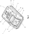
- FIG. 4 shows another perspective view of the battery 1 with the upper housing shell 14 and the locking mechanism 5 removed.
- the battery 1 has at least one wet space 6, 7 in the housing 2, in which the contacting device 4 and/or the locking mechanism 5 is arranged.
- a first wet space 6 is shown in which the locking mechanism 5 is arranged, which, as already mentioned, is not shown here.
- a second wet room 7 is shown here, in which the contacting device 4 is arranged.
- the battery 1 comprises at least one sealing device 17, which seals the interior 3 in a watertight manner from the at least one wet space 6, 7.
- a first sealing device 17 is shown here, which seals the interior 3 in a watertight manner from the first wet space 6.
- the water can then be removed from the at least one wet space 6, 7 by, for example, pressing the actuating element 9. This can create a gap 18 between the actuating element 9 and the Housing upper shell 14 can be formed, through which in this example the water can leave the first wet space 6.
- a first separating device 19 is also shown. With the help of the first or at least one separating device 19, the corresponding wet space 6, 7 can be sealed watertight from the interior 3.
- the first or at least one separating device 19 is, as shown here, designed as a tub or is tub-shaped, for example, so that the water can be collected in the corresponding wet space 6, 7, preventing the water from entering the interior 3.
- the display unit 12 comprises a light guide 23, with which the light from LEDs located below the first separating device 19 can be guided to the outside 24 of the housing 2 or the battery 1.
- a total of three light guides 23 are shown here, with only one light guide 23 being provided with a reference number.
- the switch 11 is designed here as an extension, since the actual switch 11, i.e. the electrical switch, can be arranged below the first separating device 19. This will be discussed below for Figure 5 discussed in more detail.
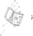
- the first separating device 19 is in the Figure 5 shown in more detail.
- the first separating device 19 can at least partially comprise the first sealing device 17.
- the first sealing device 17 comprises a sealing groove 20.
- a sealing element can be introduced into this sealing groove 20.
- the sealing element can be, for example, a sealing compound that is injected into the sealing groove 20.
- the sealing element can also be a rubber that is inserted into the sealing groove 20.
- a switch cover 21 is shown here, under which the actual electrical switch 11 is located.
- the switch 11 shown in the previous figures can, as in the corresponding figures, be designed as an extension, so that the switch 11, which is arranged below the first separating device 19, can be actuated on the outside of the housing 2 and/or the battery 1.
- the first separating device 19 comprises a display cover 22.
- the LEDs of the display unit 12 can be arranged under the display cover 22. The light from the LEDs can be guided to the outside 24 via the light guides 23.
- the switch cover 21 and/or the display cover 22 can protect the LEDs and/or the electrical switch 11 from the water in the first wet space 6.
- the switch cover 21 and/or the display cover 22 are advantageously designed to be waterproof.
- Figure 6 shows the upper housing shell 14 from above or with a view of the outside 24.
- the housing upper shell 14 has at least one opening 25 - 35 for the locking element 8, the actuating element 9, the display unit 12, the light guides 23, the switch 11 and/or the contact elements 10.
- the housing upper shell 14 has a first opening 25 for the actuating element 9.
- the housing upper shell 14 has a second opening 26 for the locking element 8.
- the housing upper shell 14 has a third opening 27, a fourth opening 28 and a fifth opening 29 for the three light guides 23.
- the housing upper shell 14 has a sixth opening 30 for the switch 11 or the extension for the switch 11.
- the housing upper shell 14 has a seventh, an eighth, a ninth, a tenth and an eleventh opening 31 - 35 for the respective contact elements 10 of the Contacting device 4.
- the openings 25 - 35 shown here can be present in any combination.
- the corresponding elements extend to the outside 24 through the respective openings 25 - 35.
- water can enter the housing 2 through the openings 25 - 35.
- the at least one wet space 6, 7 and the at least one sealing device 17 are provided for this purpose, so that the water does indeed enter the at least one wet space 6, 7, but not into the interior 3.
- the gap 18 can be formed between the actuating element 9 and the housing 2 or the housing upper shell 14 by actuating the actuating element 9, so that the water can escape through the first and/or the second opening 25, 26.
- the gap 18 is in the Figure 2 shown in which the actuating element 9 is actuated or pressed.
- a further gap 18 can also be formed between the locking element 8 and the housing 2 or the housing upper shell 14, so that water can escape through the second opening 26.
- Figure 7 shows a perspective view from below into the upper housing shell 14. Here the openings 25 - 35 can be seen again.
- first sealing device 17 is also shown here.
- the first sealing device 17 shown here can, for example, be a counterpart to the first sealing groove 20 according to the Figure 5 be.
- the first sealing device 17 is arranged and/or formed between the first separating device 19 and the housing 2 or the housing upper shell 14. As a result the housing 2 or the housing upper shell 14 as well as the first separating device 19 delimit the first wet space 6.
- Figure 8 shows a perspective view of the battery 1, wherein a second separating device 36 can be seen. With the help of the second separating device 36, the second wet space 7 can be separated from the interior space 3 in a watertight manner.
- a second sealing device (not shown here) can be arranged between the separating device 36 and the circuit board 16 and/or between the separating device 36 and the housing 2 or the housing upper shell 14.
- the first and the second sealing device can be designed identically to one another.
- the battery 1 has at least one moisture sensor 37, by means of which moisture or water can be detected.
- the moisture sensor 37 is arranged in the second wet space 7 and/or in the area of the contacting device 4.
- the moisture sensor 37 comprises a sensor element, which can be a probe 39.
- the probe 39 can protrude into the corresponding second wet space 7.
- the sensor element can also be at least one of the four contact elements 10 shown here.
- the control unit 38 can determine the moisture, for example based on a potential shift. This allows the moisture in the second wet space 7 and/or in the area of the contacting device 4 to be detected.
- the contact elements 10 are arranged in the second wet space 7 and/or in the area of the contacting device 4, so that moisture in this area can lead to damage to the battery 1 or the energy storage unit.
- the battery 1 also has a control unit 38, which is connected in particular to the at least one humidity sensor 37. If the humidity is determined using the humidity sensor 37, the control unit 38 can put the battery 1 into a safety state so that the battery 1 is protected from damage. For example, the control unit 38 can de-energize the contact elements 10.
- the control unit 38 can also be part of the humidity sensor 37.
- the control unit 38 or a part of the control unit 38 can determine the humidity by means of the sensor element, in particular the probe 39 and/or the contact element 10.
- the battery 1 can also have further moisture sensors 37 and/or sensor elements (10, 39). Additionally or alternatively, a moisture sensor 37 and/or the sensor element (10, 39) can also be arranged in the first wet space 6 and/or in the interior 3.
- the at least one moisture sensor 37 can be designed as a capacitive sensor.
- the at least one moisture sensor 37 can also, as indicated here, be designed as a pin that projects into the second wet space 7 and/or into the area of the contacting device 4.
Landscapes
- Chemical & Material Sciences (AREA)
- Chemical Kinetics & Catalysis (AREA)
- Electrochemistry (AREA)
- General Chemical & Material Sciences (AREA)
- Engineering & Computer Science (AREA)
- Manufacturing & Machinery (AREA)
- Microelectronics & Electronic Packaging (AREA)
- Life Sciences & Earth Sciences (AREA)
- Biophysics (AREA)
- Computer Hardware Design (AREA)
- Battery Mounting, Suspending (AREA)
- Portable Power Tools In General (AREA)
Applications Claiming Priority (2)
| Application Number | Priority Date | Filing Date | Title |
|---|---|---|---|
| DE102023118225 | 2023-07-10 | ||
| DE102023119394.5A DE102023119394A1 (de) | 2023-07-10 | 2023-07-21 | Akkumulator für Arbeitsgeräte |
Publications (2)
| Publication Number | Publication Date |
|---|---|
| EP4492529A2 true EP4492529A2 (fr) | 2025-01-15 |
| EP4492529A3 EP4492529A3 (fr) | 2025-03-19 |
Family
ID=91782072
Family Applications (1)
| Application Number | Title | Priority Date | Filing Date |
|---|---|---|---|
| EP24185867.9A Pending EP4492529A3 (fr) | 2023-07-10 | 2024-07-02 | Accumulateur pour outils électriques |
Country Status (1)
| Country | Link |
|---|---|
| EP (1) | EP4492529A3 (fr) |
Citations (1)
| Publication number | Priority date | Publication date | Assignee | Title |
|---|---|---|---|---|
| DE102011081819A1 (de) | 2011-08-30 | 2013-02-28 | Robert Bosch Gmbh | Akkumulator |
Family Cites Families (3)
| Publication number | Priority date | Publication date | Assignee | Title |
|---|---|---|---|---|
| DE102013223320A1 (de) * | 2013-11-15 | 2015-06-25 | Robert Bosch Gmbh | Batterievorrichtung |
| WO2023039723A1 (fr) * | 2021-09-14 | 2023-03-23 | 东莞新能安科技有限公司 | Bloc-batterie et dispositif électrique |
| CN114335777A (zh) * | 2021-12-30 | 2022-04-12 | 江苏春兰清洁能源研究院有限公司 | 具有被动除湿和主动控湿功能的电池包及被动除湿功能的控制方法 |
-
2024
- 2024-07-02 EP EP24185867.9A patent/EP4492529A3/fr active Pending
Patent Citations (1)
| Publication number | Priority date | Publication date | Assignee | Title |
|---|---|---|---|---|
| DE102011081819A1 (de) | 2011-08-30 | 2013-02-28 | Robert Bosch Gmbh | Akkumulator |
Also Published As
| Publication number | Publication date |
|---|---|
| EP4492529A3 (fr) | 2025-03-19 |
Similar Documents
| Publication | Publication Date | Title |
|---|---|---|
| DE102008022982B4 (de) | Hochspannungsverriegelungsverbindung | |
| EP3122589B1 (fr) | Dispositif embrochable réalisé sous forme de prolongateur ou de fiche | |
| WO2011054584A1 (fr) | Batterie pourvue d'un système de dégazage et procédé d'évacuation de dégagements | |
| EP3642892A1 (fr) | Dispositif interface de bloc-batterie | |
| DE19848554A1 (de) | Einen Schalter aufweisender Stecker | |
| EP3531472B1 (fr) | Bloc d'accumulateur et appareil d'outil électrique | |
| DE102014211458A1 (de) | Starthilfekabel-Halteaufbau | |
| EP3531470B1 (fr) | Bloc d'accumulateur et appareil d'outil électrique | |
| DE202008003787U1 (de) | Leuchtende Werkzeuganordnung | |
| DE102020200317A1 (de) | Akkupack für eine Handwerkzeugmaschine, Handwerkzeugmaschine und Ladegerät | |
| DE102019203296A1 (de) | Hochvolt-Vorrichtung | |
| WO2009033865A1 (fr) | Chargeur à deux modules | |
| DE8505814U1 (de) | Elektrowerkzeug | |
| EP3364493A1 (fr) | Bloc batterie avec un détecteur de température | |
| EP4492529A2 (fr) | Accumulateur pour outils électriques | |
| DE102023119394A1 (de) | Akkumulator für Arbeitsgeräte | |
| DE202019104805U1 (de) | Verbindungsvorrichtung für Leuchtmitteltreiber | |
| CH666143A5 (de) | Batteriepaket. | |
| DE112021004607T5 (de) | Eine Batterie und ein modulares Batteriesystem für ein Elektrowerkzeug | |
| DE2839911A1 (de) | Elektrische zahnbuerste | |
| DE102010027406B4 (de) | Elektrogerät | |
| EP3758976A1 (fr) | Connecteur de charge pour un véhicule à moteur | |
| EP0411281B1 (fr) | Borne électrique | |
| DE60302376T2 (de) | Schutzschalter | |
| DE102020201267A1 (de) | Akkuschnittstelle, Verbraucher mit einer Akkuschnittstelle und System aufweisend einen Verbraucher und einen Akkupack |
Legal Events
| Date | Code | Title | Description |
|---|---|---|---|
| PUAI | Public reference made under article 153(3) epc to a published international application that has entered the european phase |
Free format text: ORIGINAL CODE: 0009012 |
|
| STAA | Information on the status of an ep patent application or granted ep patent |
Free format text: STATUS: THE APPLICATION HAS BEEN PUBLISHED |
|
| AK | Designated contracting states |
Kind code of ref document: A2 Designated state(s): AL AT BE BG CH CY CZ DE DK EE ES FI FR GB GR HR HU IE IS IT LI LT LU LV MC ME MK MT NL NO PL PT RO RS SE SI SK SM TR |
|
| PUAL | Search report despatched |
Free format text: ORIGINAL CODE: 0009013 |
|
| AK | Designated contracting states |
Kind code of ref document: A3 Designated state(s): AL AT BE BG CH CY CZ DE DK EE ES FI FR GB GR HR HU IE IS IT LI LT LU LV MC ME MK MT NL NO PL PT RO RS SE SI SK SM TR |
|
| RIC1 | Information provided on ipc code assigned before grant |
Ipc: H02H 5/08 20060101ALI20250213BHEP Ipc: H01M 50/284 20210101ALI20250213BHEP Ipc: H01M 50/247 20210101ALI20250213BHEP Ipc: H01M 50/233 20210101ALI20250213BHEP Ipc: H01M 10/48 20060101ALI20250213BHEP Ipc: H01M 10/42 20060101AFI20250213BHEP |
|
| STAA | Information on the status of an ep patent application or granted ep patent |
Free format text: STATUS: REQUEST FOR EXAMINATION WAS MADE |
|
| 17P | Request for examination filed |
Effective date: 20250918 |