EP4492568A1 - Structure d'antenne et dispositif électronique la comprenant - Google Patents
Structure d'antenne et dispositif électronique la comprenant Download PDFInfo
- Publication number
- EP4492568A1 EP4492568A1 EP23781197.1A EP23781197A EP4492568A1 EP 4492568 A1 EP4492568 A1 EP 4492568A1 EP 23781197 A EP23781197 A EP 23781197A EP 4492568 A1 EP4492568 A1 EP 4492568A1
- Authority
- EP
- European Patent Office
- Prior art keywords
- electronic device
- housing
- antenna
- sidewall
- rail
- Prior art date
- Legal status (The legal status is an assumption and is not a legal conclusion. Google has not performed a legal analysis and makes no representation as to the accuracy of the status listed.)
- Pending
Links
Images










Classifications
-
- H—ELECTRICITY
- H01—ELECTRIC ELEMENTS
- H01Q—ANTENNAS, i.e. RADIO AERIALS
- H01Q1/00—Details of, or arrangements associated with, antennas
- H01Q1/12—Supports; Mounting means
- H01Q1/22—Supports; Mounting means by structural association with other equipment or articles
- H01Q1/24—Supports; Mounting means by structural association with other equipment or articles with receiving set
- H01Q1/241—Supports; Mounting means by structural association with other equipment or articles with receiving set used in mobile communications, e.g. GSM
- H01Q1/242—Supports; Mounting means by structural association with other equipment or articles with receiving set used in mobile communications, e.g. GSM specially adapted for hand-held use
- H01Q1/243—Supports; Mounting means by structural association with other equipment or articles with receiving set used in mobile communications, e.g. GSM specially adapted for hand-held use with built-in antennas
-
- G—PHYSICS
- G06—COMPUTING OR CALCULATING; COUNTING
- G06F—ELECTRIC DIGITAL DATA PROCESSING
- G06F1/00—Details not covered by groups G06F3/00 - G06F13/00 and G06F21/00
- G06F1/16—Constructional details or arrangements
- G06F1/1613—Constructional details or arrangements for portable computers
- G06F1/1633—Constructional details or arrangements of portable computers not specific to the type of enclosures covered by groups G06F1/1615 - G06F1/1626
- G06F1/1637—Details related to the display arrangement, including those related to the mounting of the display in the housing
- G06F1/1652—Details related to the display arrangement, including those related to the mounting of the display in the housing the display being flexible, e.g. mimicking a sheet of paper, or rollable
-
- G—PHYSICS
- G06—COMPUTING OR CALCULATING; COUNTING
- G06F—ELECTRIC DIGITAL DATA PROCESSING
- G06F1/00—Details not covered by groups G06F3/00 - G06F13/00 and G06F21/00
- G06F1/16—Constructional details or arrangements
- G06F1/1613—Constructional details or arrangements for portable computers
- G06F1/1633—Constructional details or arrangements of portable computers not specific to the type of enclosures covered by groups G06F1/1615 - G06F1/1626
- G06F1/1684—Constructional details or arrangements related to integrated I/O peripherals not covered by groups G06F1/1635 - G06F1/1675
- G06F1/1698—Constructional details or arrangements related to integrated I/O peripherals not covered by groups G06F1/1635 - G06F1/1675 the I/O peripheral being a sending/receiving arrangement to establish a cordless communication link, e.g. radio or infrared link, integrated cellular phone
-
- H—ELECTRICITY
- H01—ELECTRIC ELEMENTS
- H01Q—ANTENNAS, i.e. RADIO AERIALS
- H01Q1/00—Details of, or arrangements associated with, antennas
- H01Q1/08—Means for collapsing antennas or parts thereof
-
- H—ELECTRICITY
- H01—ELECTRIC ELEMENTS
- H01Q—ANTENNAS, i.e. RADIO AERIALS
- H01Q21/00—Antenna arrays or systems
- H01Q21/28—Combinations of substantially independent non-interacting antenna units or systems
-
- H—ELECTRICITY
- H04—ELECTRIC COMMUNICATION TECHNIQUE
- H04M—TELEPHONIC COMMUNICATION
- H04M1/00—Substation equipment, e.g. for use by subscribers
- H04M1/02—Constructional features of telephone sets
- H04M1/0202—Portable telephone sets, e.g. cordless phones, mobile phones or bar type handsets
- H04M1/0206—Portable telephones comprising a plurality of mechanically joined movable body parts, e.g. hinged housings
- H04M1/0208—Portable telephones comprising a plurality of mechanically joined movable body parts, e.g. hinged housings characterized by the relative motions of the body parts
- H04M1/0235—Slidable or telescopic telephones, i.e. with a relative translation movement of the body parts; Telephones using a combination of translation and other relative motions of the body parts
- H04M1/0237—Sliding mechanism with one degree of freedom
-
- H—ELECTRICITY
- H04—ELECTRIC COMMUNICATION TECHNIQUE
- H04M—TELEPHONIC COMMUNICATION
- H04M1/00—Substation equipment, e.g. for use by subscribers
- H04M1/02—Constructional features of telephone sets
- H04M1/0202—Portable telephone sets, e.g. cordless phones, mobile phones or bar type handsets
- H04M1/026—Details of the structure or mounting of specific components
- H04M1/0266—Details of the structure or mounting of specific components for a display module assembly
- H04M1/0268—Details of the structure or mounting of specific components for a display module assembly including a flexible display panel
-
- H—ELECTRICITY
- H01—ELECTRIC ELEMENTS
- H01Q—ANTENNAS, i.e. RADIO AERIALS
- H01Q1/00—Details of, or arrangements associated with, antennas
- H01Q1/27—Adaptation for use in or on movable bodies
- H01Q1/273—Adaptation for carrying or wearing by persons or animals
Definitions
- an electronic device e.g., an antenna structure and an electronic device including the same.
- the term "electronic device” may mean a device performing a particular function according to its equipped program, such as a home appliance, an electronic scheduler, a portable multimedia player, a mobile communication terminal, a tablet PC, a video/sound device, a desktop PC or laptop computer, a navigation for automobile, etc.
- electronic devices may output stored information as voices or images.
- an electronic device such as a mobile communication terminal, is recently being equipped with various functions.
- an electronic device comes with the integrated functionality, including an entertainment function, such as playing video games, a multimedia function, such as replaying music/videos, a communication and security function for mobile banking, and a scheduling or e-wallet function. These electronic devices have been downsized to be conveniently carried by users.
- the display of the electronic device may be increased to allow the user satisfactory use of multimedia services as well as voice call or text messaging services.
- An electronic device may include a display having a flat surface or having a flat surface and a curved surface.
- An electronic device including a display may be limited in implementing a screen larger than the size of the electronic device due to the structure of the fixed display. Accordingly, research has been conducted on electronic devices including a rollable display.
- an electronic device including a rollable display at least a portion of the rollable display may be unrolled or rolled when the housing of the electronic device is opened or closed so that the size of the display may be extended or shrunken.
- An electronic device including a rollable display may include a plurality of housings configured to slide relative to each other to extend or shrink the rollable display.
- a housing of an electronic device including a rollable display may include a first housing and a second housing for guiding a sliding movement of the first housing.
- an antenna structure or an antenna radiator may be formed or disposed in each of the first housing and the second housing. At least one of the antenna structure or the antenna radiator formed in each of the first housing and the second housing is sealed or covered by the other housing when the housing is closed, making it difficult to sufficiently secure antenna performance. For example, in the closed state of the electronic device, the antenna structure or antenna radiator formed in the second housing is covered by the first housing not to be exposed to the outside, resulting in deterioration of the antenna performance.
- an electronic device may comprise a first housing including a first antenna, a second housing including a second antenna and configured to slide with respect to the first housing, a display including a first display area and a second display area extending from the first display area, wherein at least a portion of the second display area is configured to be movable based on a sliding movement of the second housing, and a linear motion guide electrically connecting the first antenna of the first housing and a second antenna of the second housing.
- the linear motion guide may include a rail electrically connected to the first antenna and fixed to the first side portion, a head electrically connected to the second antenna, fixed to the second portion, and slidably fastened to the rail, and a ball bearing disposed between the head and the rail, electrically connecting the head and the rail, and configured to assist a sliding movement of the head.
- the second side portion may be disposed to be covered by the first side portion when the second housing is in a slide-in state with respect to the first housing and the second side portion may be disposed not to be at least partially covered by the first side portion when the second housing is in a slide-out state with respect to the first housing.
- the antenna performance of the antenna radiator configured of the conductive portion of the second housing can be secured.
- a connecting terminal 178 may include a connector via which the electronic device 101 may be physically connected with the external electronic device (e.g., the electronic device 102).
- the connecting terminal 178 may include, for example, a HDMI connector, a USB connector, a SD card connector, or an audio connector (e.g., a headphone connector).
- the haptic module 179 may convert an electrical signal into a mechanical stimulus (e.g., a vibration or motion) or electrical stimulus which may be recognized by a user via his tactile sensation or kinesthetic sensation.
- the haptic module 179 may include, for example, a motor, a piezoelectric element, or an electric stimulator.
- the camera module 180 may capture a still image or moving images.
- the camera module 180 may include one or more lenses, image sensors, image signal processors, or flashes.
- the power management module 188 may manage power supplied to the electronic device 101.
- the power management module 188 may be implemented as at least part of, for example, a power management integrated circuit (PMIC).
- PMIC power management integrated circuit
- the battery 189 may supply power to at least one component of the electronic device 101.
- the battery 189 may include, for example, a primary cell which is not rechargeable, a secondary cell which is rechargeable, or a fuel cell.
- the communication module 190 may support establishing a direct (e.g., wired) communication channel or a wireless communication channel between the electronic device 101 and the external electronic device (e.g., the electronic device 102, the electronic device 104, or the server 108) and performing communication via the established communication channel.
- the communication module 190 may include one or more communication processors that are operable independently from the processor 120 (e.g., the application processor (AP)) and supports a direct (e.g., wired) communication or a wireless communication.
- AP application processor
- a corresponding one of these communication modules may communicate with the external electronic device 104 via a first network 198 (e.g., a short-range communication network, such as Bluetooth TM wireless-fidelity (Wi-Fi) direct, or infrared data association (IrDA)) or a second network 199 (e.g., a long-range communication network, such as a legacy cellular network, a 5G network, a next-generation communication network, the Internet, or a computer network (e.g., local area network (LAN) or wide area network (WAN)).
- a short-range communication network such as Bluetooth TM wireless-fidelity (Wi-Fi) direct, or infrared data association (IrDA)
- a second network 199 e.g., a long-range communication network, such as a legacy cellular network, a 5G network, a next-generation communication network, the Internet, or a computer network (e.g., local area network (LAN) or wide area network (WAN)).
- LAN local
- the wireless communication module 192 may identify or authenticate the electronic device 101 in a communication network, such as the first network 198 or the second network 199, using subscriber information (e.g., international mobile subscriber identity (IMSI)) stored in the subscriber identification module 196.
- subscriber information e.g., international mobile subscriber identity (IMSI)
- the wireless communication module 192 may support a 5G network, after a 4G network, and next-generation communication technology, e.g., new radio (NR) access technology.
- the NR access technology may support enhanced mobile broadband (eMBB), massive machine type communications (mMTC), or ultra-reliable and low-latency communications (URLLC).
- eMBB enhanced mobile broadband
- mMTC massive machine type communications
- URLLC ultra-reliable and low-latency communications
- the wireless communication module 192 may support a high-frequency band (e.g., the mmWave band) to achieve, e.g., a high data transmission rate.
- the wireless communication module 192 may support various technologies for securing performance on a high-frequency band, such as, e.g., beamforming, massive multiple-input and multiple-output (massive MIMO), full dimensional MIMO (FD-MIMO), array antenna, analog beam-forming, or large scale antenna.
- the wireless communication module 192 may support various requirements specified in the electronic device 101, an external electronic device (e.g., the electronic device 104), or a network system (e.g., the second network 199).
- the wireless communication module 192 may support a peak data rate (e.g., 20Gbps or more) for implementing eMBB, loss coverage (e.g., 164dB or less) for implementing mMTC, or U-plane latency (e.g., 0.5ms or less for each of downlink (DL) and uplink (UL), or a round trip of 1ms or less) for implementing URLLC.
- a peak data rate e.g., 20Gbps or more
- loss coverage e.g., 164dB or less
- U-plane latency e.g., 0.5ms or less for each of downlink (DL) and uplink (UL), or a round trip of 1ms or less
- the antenna module 197 may transmit or receive a signal or power to or from the outside (e.g., the external electronic device).
- the antenna module 197 may include one antenna including a radiator formed of a conductor or conductive pattern formed on a substrate (e.g., a printed circuit board (PCB)).
- the antenna module 197 may include a plurality of antennas (e.g., an antenna array). In this case, at least one antenna appropriate for a communication scheme used in a communication network, such as the first network 198 or the second network 199, may be selected from the plurality of antennas by, e.g., the communication module 190.
- the signal or the power may then be transmitted or received between the communication module 190 and the external electronic device via the selected at least one antenna.
- other parts e.g., radio frequency integrated circuit (RFIC)
- RFIC radio frequency integrated circuit
- the antenna module 197 may form a mmWave antenna module.
- the mmWave antenna module may include a printed circuit board, a RFIC disposed on a first surface (e.g., the bottom surface) of the printed circuit board, or adjacent to the first surface and capable of supporting a designated high-frequency band (e.g., the mmWave band), and a plurality of antennas (e.g., array antennas) disposed on a second surface (e.g., the top or a side surface) of the printed circuit board, or adjacent to the second surface and capable of transmitting or receiving signals of the designated high-frequency band.
- a RFIC disposed on a first surface (e.g., the bottom surface) of the printed circuit board, or adjacent to the first surface and capable of supporting a designated high-frequency band (e.g., the mmWave band)
- a plurality of antennas e.g., array antennas
- At least some of the above-described components may be coupled mutually and communicate signals (e.g., commands or data) therebetween via an inter-peripheral communication scheme (e.g., a bus, general purpose input and output (GPIO), serial peripheral interface (SPI), or mobile industry processor interface (MIPI)).
- an inter-peripheral communication scheme e.g., a bus, general purpose input and output (GPIO), serial peripheral interface (SPI), or mobile industry processor interface (MIPI)
- commands or data may be transmitted or received between the electronic device 101 and the external electronic device 104 via the server 108 coupled with the second network 199.
- the external electronic devices 102 or 104 each may be a device of the same or a different type from the electronic device 101.
- all or some of operations to be executed at the electronic device 101 may be executed at one or more of the external electronic devices 102, 104, or 108. For example, if the electronic device 101 should perform a function or a service automatically, or in response to a request from a user or another device, the electronic device 101, instead of, or in addition to, executing the function or the service, may request the one or more external electronic devices to perform at least part of the function or the service.
- the one or more external electronic devices receiving the request may perform the at least part of the function or the service requested, or an additional function or an additional service related to the request, and transfer an outcome of the performing to the electronic device 101.
- the electronic device 101 may provide the outcome, with or without further processing of the outcome, as at least part of a reply to the request.
- a cloud computing, distributed computing, mobile edge computing (MEC), or client-server computing technology may be used, for example.
- the electronic device 101 may provide ultra low-latency services using, e.g., distributed computing or mobile edge computing.
- the external electronic device 104 may include an Internet-of-things (IoT) device.
- the server 108 may be an intelligent server using machine learning and/or a neural network.
- the external electronic device 104 or the server 108 may be included in the second network 199.
- the electronic device 101 may be applied to intelligent services (e.g., smart home, smart city, smart car, or health-care) based on 5G communication technology or IoT-related technology.
- the electronic device may be one of various types of electronic devices.
- the electronic devices may include, for example, a portable communication device (e.g., a smartphone), a computer device, a portable multimedia device, a portable medical device, a camera, a wearable device, or a home appliance.
- a portable communication device e.g., a smartphone
- a computer device e.g., a laptop, a desktop, a tablet, or a portable multimedia device
- a portable medical device e.g., a portable medical device
- camera e.g., a camera
- a wearable device e.g., a portable medical device
- each of such phrases as “A or B,” “at least one of A and B,” “at least one of A or B,” “A, B, or C,” “at least one of A, B, and C,” and “at least one of A, B, or C,” may include all possible combinations of the items enumerated together in a corresponding one of the phrases.
- such terms as “1st” and “2nd,” or “first” and “second” may be used to simply distinguish a corresponding component from another, and does not limit the components in other aspect (e.g., importance or order).
- an element e.g., a first element
- the element may be coupled with the other element directly (e.g., wiredly), wirelessly, or via a third element.
- module may include a unit implemented in hardware, software, or firmware, and may interchangeably be used with other terms, for example, “logic,” “logic block,” “part,” or “circuitry”.
- a module may be a single integral component, or a minimum unit or part thereof, adapted to perform one or more functions.
- the module may be implemented in a form of an application-specific integrated circuit (ASIC).
- ASIC application-specific integrated circuit
- Various embodiments as set forth herein may be implemented as software (e.g., the program 140) including one or more instructions that are stored in a storage medium (e.g., internal memory 136 or external memory 138) that is readable by a machine (e.g., the electronic device 101).
- a processor e.g., the processor 120
- the machine e.g., the electronic device 101
- the one or more instructions may include a code generated by a complier or a code executable by an interpreter.
- the storage medium readable by the machine may be provided in the form of a non-transitory storage medium.
- the term “non-transitory” simply means that the storage medium is a tangible device, and does not include a signal (e.g., an electromagnetic wave), but this term does not differentiate between where data is semi-permanently stored in the storage medium and where the data is temporarily stored in the storage medium.
- a method may be included and provided in a computer program product.
- the computer program products may be traded as commodities between sellers and buyers.
- the computer program product may be distributed in the form of a machine-readable storage medium (e.g., compact disc read only memory (CD-ROM)), or be distributed (e.g., downloaded or uploaded) online via an application store (e.g., Play Store TM ), or between two user devices (e.g., smart phones) directly. If distributed online, at least part of the computer program product may be temporarily generated or at least temporarily stored in the machine-readable storage medium, such as memory of the manufacturer's server, a server of the application store, or a relay server.
- CD-ROM compact disc read only memory
- an application store e.g., Play Store TM
- two user devices e.g., smart phones
- each component e.g., a module or a program of the above-described components may include a single entity or multiple entities. Some of the plurality of entities may be separately disposed in different components. According to various embodiments, one or more of the above-described components may be omitted, or one or more other components may be added. Alternatively or additionally, a plurality of components (e.g., modules or programs) may be integrated into a single component. In such a case, according to various embodiments, the integrated component may still perform one or more functions of each of the plurality of components in the same or similar manner as they are performed by a corresponding one of the plurality of components before the integration.
- operations performed by the module, the program, or another component may be carried out sequentially, in parallel, repeatedly, or heuristically, or one or more of the operations may be executed in a different order or omitted, or one or more other operations may be added.
- FIG. 2 is a view illustrating a state in which a second display area of a display is received in a housing according to an embodiment of the disclosure.
- FIG. 3 is a view illustrating a state in which a second display area of a display is exposed to the outside of a housing according to an embodiment of the disclosure.
- FIGS. 2 and 3 illustrate a structure in which the display 203 (e.g., flexible display or rollable display) is extended in the length direction (e.g., +Y direction) when the electronic device 101 is viewed from the front.
- the extending direction of the display 203 is not limited to one direction (e.g., +Y direction).
- the extending direction of the display 203 may be changed in design to be extendable in the upper direction (+Y direction), right direction (e.g., +X direction), left direction (e.g., -X direction), and/or lower direction (e.g., -Y direction).
- the state illustrated in FIG. 2 may be referred to as a slide-in state of the electronic device 101 or a state in which the second display area A2 of the display 203 is closed.
- the state illustrated in FIG. 3 may be referred to as a slide-out state of the electronic device 101 or a state in which the second display area A2 of the display 203 is open.
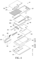
- the electronic device 101 may include a housing 210.
- the housing 210 may include a first housing 201 and a second housing 202 disposed to be movable relative to the first housing 201.
- the electronic device 101 may be interpreted as having a structure in which the first housing 201 is disposed to be slidable with respect to the second housing 202.
- the second housing 202 may be disposed to perform reciprocating motion by a predetermined distance in a predetermined direction with respect to the first housing 201, for example, a direction indicated by an arrow 1.
- the second housing 202 may be referred to as a slide portion or a slide housing, and may be movable relative to the first housing 201. According to an embodiment, the second housing 202 may receive various electrical and electronic components, such as a circuit board or a battery.
- the first housing 201 may receive a motor, a speaker, a sim socket, and/or a sub circuit board electrically connected with a main circuit board.
- the second housing 202 may receive a main circuit board on which electric components, such as an application processor (AP) and a communication processor (CP) are mounted.
- AP application processor
- CP communication processor
- the first housing 201 may include a first cover member 211 (e.g., a main case).
- the first cover member 211 may include a 1-1th sidewall 211a, a 1-2th sidewall 211b extending from the 1-1th sidewall 211a, and a 1-3th sidewall 211c extending from the 1-1th sidewall 211a and substantially parallel to the 1-2th sidewall 211b.
- the 1-2th sidewall 211b and the 1-3th sidewall 211c may be formed substantially perpendicular to the 1-1th sidewall 211a.
- the 1-1th sidewall 211a, 1-2th sidewall 211b, and 1-3th sidewall 211c of the first cover member 211 may be formed to have a side opening (e.g., front opening) to receive (or surround) at least a portion of the second housing 202.
- a side opening e.g., front opening
- at least a portion of the second housing 202 may be surrounded by the first housing 201 and be slid in the direction parallel to the first surface (e.g., the first surface F1 of FIG. 4 ), e.g., arrow 1 direction, while being guided by the first housing 201.
- the 1-1th sidewall 211a, the 1-2th sidewall 211b, and/or the 1-3th sidewall 211c of the first cover member 211 may be integrally formed. According to an embodiment, the 1-1th sidewall 211a, the 1-2th sidewall 211b, and/or the 1-3th sidewall 211c of the first cover member 211 may be formed as separate structures and be combined or assembled.
- the first cover member 211 may be formed to surround at least a portion of the display 203.
- at least a portion of the display 203 may be formed to be surrounded by the 1-1th sidewall 211a, the 1-2th sidewall 211b, and/or the 1-3th sidewall 211c of the first cover member 211.
- the second housing 202 may include a second cover member 221 (e.g., a slide plate).
- the second cover member 221 may have a plate shape and include a first surface (e.g., the first surface F1 of FIG. 4 ) supporting internal components.
- the second cover member 221 may support at least a portion of the display 203 (e.g., the first display area A1).
- the second cover member 221 may be referred to as a front cover.
- the second cover member 221 may include a 2-1th sidewall 221a, a 2-2th sidewall 221b extending from the 2-1th sidewall 221a, and a 2-3th sidewall 221c extending from the 2-1th sidewall 221a and substantially parallel to the 2-2th sidewall 221b.
- the 2-2th sidewall 221b and the 2-3th sidewall 221c may be formed substantially perpendicular to the 2-1th sidewall 221a.
- the slide-in state and slide-out state of the electronic device 101 may be formed.
- the second housing 202 may be positioned at a first distance from the 1-1th sidewall 211a of the first housing 201.
- the second housing 202 may move to be positioned at a second distance larger than the first distance from the 1-1th sidewall 211a of the first housing 201.
- the first housing 201 may be formed to surround a portion of the 2-1th sidewall 221a.
- the electronic device 101 may have an intermediate state between the slide-in state (e.g., fully opened state) of FIG. 2 and the slide-out state (e.g., fully closed state) of FIG. 3 .
- the distance between the 1-1th sidewall 211a and the 2-1th sidewall 221a in the intermediate state of the electronic device 101 may be shorter than the distance between the 1-1th sidewall 211a and the 2-1th sidewall 221a of the electronic device 101 in the fully open state and be longer than the distance between the 1-1th sidewall 211a and the 2-1th sidewall 221a of the electronic device 101 in the fully closed state.
- the area exposed to the outside may vary.
- the ratio of the width (length in the X direction) to the height (length in the Y direction) of the display 203 and/or the distance between the 1-1th sidewall 211a and the 2-1th sidewall 221a may be changed based on the slide of the electronic device 101.
- the electronic device 101 may include a display 203, a key input device 245, a connector hole 243, audio modules 247a and 247b, or camera modules 249a and 249b.
- the electronic device 101 may further include an indicator (e.g., a light emitting diode (LED) device) or various sensor modules.
- an indicator e.g., a light emitting diode (LED) device
- the first display area A1 of the display 231 may be visually exposed, and at least a portion (e.g., a portion along the -Z axis) of the second display area A2 may be disposed between the battery 289 and the first rear plate 215.
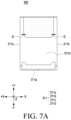
- the 2-2th sidewall 321b in the closed state (e.g., FIG. 2 or FIG. 7A ) of the electronic device 300, the 2-2th sidewall 321b may face the 1-2th sidewall 311b, and the 2-3th sidewall 321c may face the 1-3th sidewall 311c.
- the 1-2th sidewall 311b in the closed state (e.g., FIG. 2 or 7A ) of the electronic device 300, the 1-2th sidewall 311b may cover at least a portion of the 2-2th sidewall 321b, and the 1-3th sidewall 311c may cover at least a portion of the 2-3th sidewall 321c.
- the 2-2th sidewall 321b in the closed state (e.g., FIG. 2 or FIG. 7A ) of the electronic device 300, the 2-2th sidewall 321b may face the 1-2th sidewall 311b, and the 2-3th sidewall 321c may face the 1-3th sidewall 311c.
- the 1-2th sidewall 311b in the closed state (e.g., FIG. 2 or 7A ) of the electronic device 300, the 1-2th sidewall 311b may cover at least a portion of the 2-2th sidewall 321b, and the 1-3th sidewall 311c may cover at least a portion of the 2-3th sidewall 321c.
- the second metal area may be connected to a printed circuit board (e.g., the first circuit board 248 of FIG. 4 ) through a ground line, and at least a portion of the circuit board may be used as a ground for providing a reference potential.
- a printed circuit board e.g., the first circuit board 248 of FIG. 4
- At least one of the 1-2th sidewall 311b and the 1-3th sidewall 311c may include a first metal area including a metallic material (e.g., aluminum or stainless steel) and a first non-metal area including a non-metallic material (e.g., polymer).
- a metallic material e.g., aluminum or stainless steel
- a first non-metal area including a non-metallic material (e.g., polymer).
- the first metal area of the first cover member 311 may be electrically connected to a communication module (e.g., the communication module 190 of FIG. 1 ) and may be utilized as an antenna radiator (e.g., the antenna module 197 of FIG. 1 ) of the first cover member 311 or the electronic device 300.
- the first metal area may be defined and referred to as a first antenna.
- the communication module may be electrically connected to the first metal area.
- the electronic device 300 when the electronic device 300 is in the closed state (e.g., FIG. 7A ) or is in the slide-in state (e.g., FIG. 2 or 7A ) of the second housing (e.g., the second housing 202 of FIGS. 2 and 3 ) with respect to the first housing (e.g., the first housing 201 of FIGS. 2 and 3 ), the second metal area of the 2-2th sidewall 321b and/or the 2-3th sidewall 321c of the second cover member 321 may be covered by the 1-2th sidewall 311b and/or the 1-3th sidewall 311c of the first cover member 311.
- the second metal area e.g., the second antenna
- the second metal area is covered by the 1-2th sidewall 311b and/or the 1-3th sidewall 311c
- the second metal area e.g., the second antenna
- the closed state e.g., FIG. 2 or 7A
- the antenna performance of the second metal area e.g., the second antenna
- the electronic device 300 is in the slide-in state (e.g., FIG.
- the 2-2th sidewall 321b and/or the 2-3th sidewall 321c of the second cover member 321 may be covered by the 1-2th sidewall 311b and/or the 1-3th sidewall 311c of the first cover member 311 so as not to be exposed to the outside of the first housing (e.g., the first cover member 311).
- the electronic device 300 when the electronic device 300 is in the open state (e.g., FIG. 7B ) or is in the slide-out state (e.g., FIG. 3 or FIG. 7B ) of the second housing (e.g., the second housing 202 of FIGS. 2 and 3 ) with respect to the first housing (e.g., the first housing 201 of FIGS. 2 and 3 ), the second metal area of the 2-2th sidewall 321b and/or the 2-3th sidewall 321c of the second cover member 321 may be disposed so that at least a portion thereof is exposed to the outside of the first housing (e.g., the first cover member 311).
- the slide-out state e.g., FIG.
- the 2-2th sidewall 321b and/or the 2-3th sidewall 321c of the second cover member 321 may be disposed so that at least a portion thereof is exposed to the outside of the first housing (e.g., the first cover member 311).
- the electronic device 300 may include a ground structure G that electrically connects the second metal area of the second cover member 321 and the first metal area of the first cover member 311.
- the ground structure G may electrically connect the second metal area (e.g., the second antenna) of the second cover member 321 and the first metal area (e.g., the first antenna) of the first cover member 311 to form a coupled inverted-F antenna (coupled IFA).
- the second metal area e.g., the second antenna
- the first metal area e.g., the first antenna
- the ground structure G may electrically connect an antenna radiator (e.g., the second antenna) including the 2-2th sidewall 321b of the second cover member 321 and the second metal area of the 2-3th sidewall 321c and an antenna radiator (e.g., the first antenna) including the 1-2th sidewall 311b of the first cover member 311 and the first metal area of the 1-3th sidewall 311c.
- an antenna radiator e.g., the second antenna
- the first antenna including the 1-2th sidewall 311b of the first cover member 311 and the first metal area of the 1-3th sidewall 311c.
- a circuit board e.g., the first circuit board 248 of FIG.
- the first metal area of the first cover member 311 may be transferred to the first metal area of the first cover member 311 through the ground structure G.
- power transferred to the first metal area of the first cover member 311 may be conducted to the first metal area (e.g., the first antenna) while radiating an antenna signal.
- the ground structure G may electrically connect an antenna radiator (e.g., the second antenna) including the 2-2th sidewall 321b of the second cover member 321 and the second metal area of the 2-3th sidewall 321c and an antenna radiator (e.g., the first antenna) including the 1-2th sidewall 311b of the first cover member 311 and the first metal area of the 1-3th sidewall 311c.
- an antenna radiator e.g., the second antenna
- the first antenna including the 1-2th sidewall 311b of the first cover member 311 and the first metal area of the 1-3th sidewall 311c.
- a circuit board e.g., the first circuit board 248 of FIG.
- the first metal area of the first cover member 311 may be transferred to the first metal area of the first cover member 311 through the ground structure G.
- the second metal area e.g., the second antenna
- the remaining portion of the power provided to the second cover member 321 may be transferred to the first cover member 311 to be conducted to the first metal area (e.g., the first antenna) of the first cover member 311 to radiate an antenna signal.
- the ground structure G may radiate an antenna signal through the antenna radiator (e.g., the first antenna) formed in the first metal area in the closed state (e.g., FIG. 7A ) of the electronic device 300, thereby preventing deterioration of antenna performance.
- the antenna radiator e.g., the first antenna
- the closed state e.g., FIG. 7A
- the electronic device 300 may maintain an electrically connected state between the antenna radiator (e.g., the first antenna) formed of the first metal area and the antenna radiator (e.g., the second antenna) formed of the second metal area in the slide-in state (e.g., FIG. 2 ), the slide-out state (e.g., FIG. 3 ), or a sliding state (e.g., a state of switching from FIG. 2 to FIG. 3 , or a state switching from FIG. 3 to FIG. 2 ) of the electronic device 300.
- the antenna radiator e.g., the first antenna
- the antenna radiator e.g., the second antenna
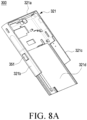
- FIG. 8A is a perspective view illustrating a second cover member according to various embodiments of the disclosure.
- FIG. 8B is a perspective view illustrating a first cover member in a closed state of an electronic device according to various embodiments of the disclosure.
- FIG. 8C is a perspective view illustrating a first cover member in an open state of an electronic device according to various embodiments of the disclosure.
- an electronic device 300 may include a second cover member 321, a first cover member 311, and a linear motion guide 350.
- the configuration of the second cover member 321, the first cover member 311, and the linear motion guide 350 of FIGS. 8A to 8C may be identical in whole or part to the configuration of the first cover member 311, the second cover member 321, and the ground structure G of FIGS. 7A to 7B .
- the second cover member 321 may include a second flat portion 321d (e.g., the second flat portion 321d of FIGS. 7A and 7B ), a 2-1th sidewall 321a (e.g., the 2-1th sidewall 321a of FIGS. 7A and 7B ), a 2-2th sidewall 321b (e.g., the 2-2th sidewall 321b of FIGS. 7A and 7B ), and a 2-3th sidewall 321c (e.g., the 2-3th sidewall 321c of FIGS. 7A to 5C).
- a second flat portion 321d e.g., the second flat portion 321d of FIGS. 7A and 7B
- a 2-1th sidewall 321a e.g., the 2-1th sidewall 321a of FIGS. 7A and 7B
- a 2-2th sidewall 321b e.g., the 2-2th sidewall 321b of FIGS. 7A and 7B
- the 2-2th sidewall 321b and the 2-3th sidewall 321c may include a second metal area (e.g., the second antenna) including a conductive portion.
- the first cover member 311 may include a first flat portion 311d (e.g., the first flat portion 311d of FIGS. 7A and 7B ), a 1-1th sidewall 311a (e.g., the 1-1th sidewall 311a of FIGS. 7A and 7B ), a 1-2th sidewall 311b (e.g., the 1-2th sidewall 311b of FIGS. 7A and 7B ), and a 1-3th sidewall 311c (e.g., the 1-3th sidewall 311c of FIGS. 7A to 5C).
- a first flat portion 311d e.g., the first flat portion 311d of FIGS. 7A and 7B
- a 1-1th sidewall 311a e.g., the 1-1th sidewall 311a of FIGS. 7A and 7B
- a 1-2th sidewall 311b e.g., the 1-2th sidewall 311b of FIGS. 7A and 7B
- the 1-2th sidewall 311b and the 1-3th sidewall 311c may include a first metal area (e.g., the first antenna) including a conductive portion.
- the electronic device 300 may further include a linear motion guide 350 (e.g., the ground structure G of FIGS. 7A and 7B ) that electrically connects the first metal area and the second metal area.
- a linear motion guide 350 e.g., the ground structure G of FIGS. 7A and 7B
- the linear motion guide 350 may include a head 351, a rail 355, and a ball bearing 353.
- the linear motion guide 350 may be defined and interpreted as a component for electrically connecting the first antenna and the second antenna.
- the head 351 of the linear motion guide 350 may be coupled or connected to the second cover member 321.
- the head 351 may be coupled to at least a portion of the 2-2th sidewall 321b of the second cover member 321 and/or at least a portion of the 2-3th sidewall 321c of the second cover member 321.
- a pair of heads 351 may be provided, and the pair of heads 351 may be coupled to an outer wall of the 2-2th sidewall 321b and an outer wall of the 2-3th sidewall 321c, respectively.
- the head 351 may be electrically connected to the second metal area (e.g., the second antenna) of the second cover member 321. According to an embodiment, the head 351 may be configured to slide along the length direction of the rail 355 on the rail 355 of the linear motion guide 350.
- the rail 355 of the linear motion guide 350 may be coupled to or connected to the first cover member 311.
- the rail 355 may be coupled to at least a portion of the 1-2th sidewall 311b of the first cover member 311 and/or at least a portion of the 1-3th sidewall 311c of the first cover member 311.
- a pair of rails 355 may be provided, and the pair of rails 355 may be coupled to an inner wall of the 1-2th sidewall 311b and an inner wall of the 1-3th sidewall 311c, respectively.
- the rail 355 may be electrically connected to a first metal area (e.g., the first antenna) of the first cover member 311. According to an embodiment, the rail 355 may be slidably fastened to the head 351 coupled to the second cover member 321.
- the second cover member 321 may slide in one direction (e.g., the +Y direction of FIG. 3 ) with respect to the first cover member 311, and the head 351 coupled to the second cover member 321 may slide in one direction (e.g., the +Y direction of FIG. 3 ) with respect to the rail 355.
- the second cover member 321 may slide in the other direction (e.g., the -Y direction of FIG. 3 ) opposite to the one direction with respect to the first cover member 311, and the head 351 coupled to the second cover member 321 may slide in the other direction (e.g., the -Y direction of FIG. 3 ) with respect to the rail 355.
- the head 351 may be electrically connected to the rail 355. Accordingly, the second metal area (e.g., the second antenna) of the second cover member 321 may be electrically connected to the first metal area of the first cover member 311 through the head 351 and the rail 355.
- the second metal area e.g., the second antenna
- the head 351 in the open state of the electronic device 300 (e.g., FIG. 7A or 8B ), the head 351 may be disposed between the second cover member 321 and the first cover member 311 so as not to be exposed to the outside of the electronic device 300.
- the ground structure e.g., the ground structure G of FIGS. 7A and 7B
- the second metal area e.g., the second antenna
- the first metal area e.g., the first antenna
- FIG. 9A is an assembled perspective view illustrating a linear motion guide according to various embodiments of the disclosure.
- FIG. 9B is a side view illustrating a linear motion guide according to various embodiments of the disclosure.
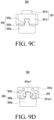
- FIG. 9C is a front view illustrating a linear motion guide according to various embodiments of the disclosure.
- FIG. 9D is a cross-sectional view taken along line A-A of FIG. 9B according to various embodiments of the disclosure.
- a linear motion guide 350 (e.g., the linear motion guide 350 of FIGS. 8A to 8C ) may include a head 351, a rail 355, and a ball bearing 353.
- the configuration of the head 351 and the rail 355 of FIGS. 9A to 9D may be identical in whole or part to the configuration of the head 351 and the rail 355 of FIGS. 8A to 8C .
- the head 351 may include a first body portion 351a, a first protrusion 351b, and a cover portion 351c.
- the first body portion 351a may form the body of the head 351.
- a pair of cover portions 351c may be coupled or connected to one side of the first body portion 351a and the other side facing away from the one side, respectively.
- the first body portion 351a may be configured to slide on the rail 355 and/or the second protrusion 355b of the rail 355.
- the first body portion 351a may include a guide groove 351a-1 recessed in at least a portion of the portion facing the rail 355.
- the guide groove 351a-1 may extend from the first body portion 351 along the extending direction of the rail 355.
- the second protrusion 355b of the rail 355 may be inserted into the guide groove 351a-1.
- the first body portion 351a may further include a first ball groove 351a-2 recessed in at least a portion of a side surface of the guide groove 351a-1. At least one ball bearing 353 may be inserted into and disposed in the first ball groove 351a-2.
- the first ball groove 351a-2 may extend from the first body portion 351 along the extending direction of the rail 355.
- the first protrusion 351b may protrude from one surface of the first body portion 351a.
- the first protrusion 351b may be defined and interpreted as a component separate from the first body portion 351a.
- the first protrusion 351b may be defined and interpreted as a partial configuration of the first body portion 351a.
- the first protrusion 351b may be inserted into a groove recessed in or a hole formed through the 2-2th sidewall (e.g., the 2-2th sidewall 311b of FIGS. 8A to 8C ) and/or the 2-3th sidewall (e.g., the 2-3th sidewall 311c of FIGS. 8A to 8C ) of the second cover member (e.g., the second cover member 321 of FIGS. 8A to 8C ).
- the first protrusion 351b may be fitted into the groove or the hole, and accordingly, the head 351 may be coupled, connected, or fixed to the 2-2th sidewall and/or the 2-3th sidewall of the second cover member (e.g., the second cover member 321 of FIG. 8A ).
- a pair of cover portions 351c may be provided, and the pair of body portions 351c may be coupled or connected to one side and the other side, respectively, of the first body portion 351a.
- the pair of cover portions 351c may be configured to prevent the ball bearing 353 inserted and disposed in the first ball groove 351a-2 of the first body portion 351a from escaping off.
- the pair of cover portions 351c may close one side and the other side of the first ball groove 351a-2, thereby preventing the at least one ball bearing 353 inserted into and disposed in the first ball groove 351a-2 from escaping off from the ball groove 351a-2.
- the cover portion 351c may be coupled to the first body portion 351a to cover the ball bearing 353.
- the cover portion 351c may include a guide groove recessed in a shape corresponding to the shape of the second protrusion 355b of the rail 355.
- a second protrusion 355b may be inserted and disposed in the guide groove of the cover portion 351c.
- the rail 355 may include a second body portion 355a, a second protrusion 355b, a second ball groove 355c, and a third protrusion 355d.
- the second body portion 355a may extend in the sliding direction (e.g., the Y-axis direction of FIG. 3 ) of the second cover member (e.g., the second cover member 311 of FIGS. 8A to 8C ).
- the second body portion 355a may form the body of the rail 355.
- the second protrusion 355b may protrude from one surface (e.g., a surface facing the head 351) of the second body portion 355a.
- the second protrusion 355b may be defined and interpreted as a component separate from the second body portion 355a.
- the second protrusion 355b may be defined and interpreted as a partial configuration of the second body portion 355a.
- the second protrusion 355b of the rail 355 may be fastened or connected to allow the head 351 to slide.
- the second protrusion 355b may extend along the extending direction of the second body portion 355a.
- the second ball groove 355c may be a groove recessed in at least a portion of the side surface of the second protrusion 355b.
- the second ball groove 355c may contact at least one ball bearing 353.
- the second ball groove 355c may extend along the extending direction of the second body portion 355a.
- the third protrusion 355d may protrude from at least a portion of the other surface (e.g., a surface facing away from the surface facing in the head 351) of the second body 355a.
- the third protrusion 355d may be defined and interpreted as a component separate from the second body portion 355a.
- the third protrusion 355d may be defined and interpreted as a partial configuration of the second body portion 355a.
- the third protrusion 355d may be inserted and disposed in a groove recessed in or a hole formed through the 1-2th sidewall (e.g., the 1-2th sidewall 321b of FIGS. 8A to 8C ) and/or the 1-3th sidewall (e.g., the 1-3th sidewall 321c of FIGS. 8A to 8C ) of the first cover member (e.g., the first cover member 321 of FIGS. 8A to 8C ).
- the third protrusion 355d may be fitted into the groove or the hole, and accordingly, the rail 355 may be coupled, connected, or fixed to the first cover member (e.g., the first cover member 311 of FIGS. 8B to 8C ).
- the linear motion guide 350 may further include at least one ball bearing 353 disposed between the head 351 and the rail 355 and configured to assist the sliding movement of the head 351.
- the ball bearing 353 may be defined and interpreted as a ball bearing.
- each of the at least one ball bearing 353 may be inserted and disposed in the first ball groove 351a-2 to contact the first ball groove 351a-2, and the other portion may be inserted and disposed in the second ball groove 355c to contact the second ball groove 355c.
- the at least one ball bearing 353 may be configured to assist the head 351 in smoothly or stably sliding on the rail 355 and to electrically connect the head 351 and the rail 355.
- FIG. 10A is an exploded perspective view illustrating a linear motion guide according to various embodiments of the disclosure.
- FIG. 10B is a perspective view illustrating a head of a linear motion guide according to various embodiments of the disclosure.
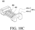
- FIG. 10C is a perspective view illustrating a head and a ball bearing of a linear motion guide according to various embodiments of the disclosure.
- FIG. 10D is a view illustrating an arrangement relationship between a ball bearing and a retainer of a linear motion guide according to various embodiments of the disclosure.
- FIG. 10E is a perspective view illustrating a retainer of a linear motion guide according to various embodiments of the disclosure.
- FIG. 11 is a cross-sectional view illustrating a coupling relationship of a linear motion guide according to various embodiments of the disclosure.
- a linear motion guide 450 may include a head 451, a rail 455, at least one ball bearing 453, and a retainer 454.
- the configuration of the head 451, the rail 455, and the at least one ball bearing 453 of FIGS. 10A to 11 may be identical in whole or part to the configuration of the head 351, the rail 355, and the at least one ball bearing 353 of FIGS. 8A to 9D .
- the head 451 may include a first body portion 451a (e.g., the first body portion 351a of FIGS. 9A to 9D ), a first protrusion 451b (e.g., the first protrusion 351b of FIGS. 9A to 9D ), and a cover portion 451c (e.g., the cover portion 351c of FIGS. 9A to 9D ).
- a first body portion 451a e.g., the first body portion 351a of FIGS. 9A to 9D
- a first protrusion 451b e.g., the first protrusion 351b of FIGS. 9A to 9D
- cover portion 451c e.g., the cover portion 351c of FIGS. 9A to 9D
- the cover portion 451c may include a first cover portion 451c-1 coupled to the first body portion 451a and a second cover portion 451c-2 coupled to the first cover portion 451c-1.
- the first cover portion 451c-1 may be configured to prevent the at least one ball bearing 451c inserted and disposed inside the first body portion 451a from escaping off.
- the first cover portion 451c-1 may be configured to cover the ball bearing 453.
- the first cover portion 451c-1 may include a ball slit 451c-12 recessed in at least a portion thereof.
- the ball slit 451c-12 of the first cover portion 451c-1 may be configured to guide circulation of the at least one ball bearing 453.
- the at least one ball bearing 453 disposed in a ring shape or a loop shape inside the first body 451a may move along the ball slit 451c-12.
- the first cover portion 451c-1 may further include a retainer slit 451c-11 recessed in a portion different from the at least one portion.
- the retainer slit 451c-11 may be recessed in a shape corresponding to the second portion 454b and the third portion 454c of the retainer 454.
- at least a portion (e.g., the second portion 454b and the third portion 454c) of the retainer 454 may be fixed to the retainer slit 451c-11 of the first cover portion 451c-1.
- the second cover portion 451c-2 may be coupled to or connected to the first cover portion 451c-1.
- the second cover portion 451c-2 may be configured to cover at least a portion (e.g., the second portion 454b and the third portion 454c) of the retainer 454 fixed to the retainer slit 451c-11.
- at least a portion of the retainer 454 may be disposed between the first cover portion 451c-1 and the second cover portion 451c-2.
- the rail 455 (e.g., the head 351 of FIGS. 9A to 9D ) may include a second body portion 455a (e.g., the second body portion 355a of FIGS. 9A to 9D ), a second protrusion 451b (e.g., the second protrusion 351b of FIGS. 9A to 9D ), a second ball groove 455c-1 (e.g., the second ball groove 355c of FIGS. 9A to 9D ), and a retainer groove 455c-2.
- the second ball groove 455c-1 and the retainer groove 455c-1 may be defined and/or interpreted as one groove 455c recessed in at least a portion of the second protrusion 451b.
- the at least one ball bearing 453 may be disposed inside the first body portion 451a.
- the at least one ball bearing 453 may be disposed along a ring-shaped or loop-shaped path formed inside the first body portion 451a.
- the at least one ball bearing 453 when the head 451 slides, the at least one ball bearing 453 may contact the second ball groove 455c-1 of the second protrusion 455b to be rotated (or spun) by the second ball groove 455c-1, and when the head 451 slides, the at least one ball bearing 453 may be rotated (or spun) along the ring shape or the loop shape on the path formed inside the first body 451a.
- the retainer 454 may include a first portion 454a inserted and disposed in the retainer groove 455c-2 and extending along the extending direction of the rail 455, a second portion 454b bent from one end of the first portion 454a and then extending, and a third portion 454c bent from one end of the second portion 454b and then extending.
- the first portion 454a of the retainer 454 may be configured to prevent the at least one ball bearing 453 from escaping off.
- the second portion 454b and the third portion 454c of the retainer 454 may be fixed to the retainer slit 451c-11 of the first cover portion 451c-1.
- the retainer 454 may be configured to cover at least a portion of the ball bearing 453.
- the linear motion guide 450 may further include a first fastening member 457 and a second fastening member 458.
- the first fastening member 457 may include a bolt or pin for fixing the first cover member and the first protrusion 451b.
- the second fastening member 458 may include a bolt or pin for fixing the first cover member and the rail 455.
- an electronic device may comprise a first housing (e.g., the first housing 201 of FIGS. 2 to 4 , the first cover member 211 of FIG. 4 , or the first cover member 311 of FIGS. 7A to 8C ) including a first side portion (e.g., the 1-2th sidewall 211b or the 1-3th sidewall 211c of FIGS. 2 and 3 or the 2-2th sidewall 311b or the 2-3th sidewall 311c of FIGS.
- a first housing e.g., the first housing 201 of FIGS. 2 to 4 , the first cover member 211 of FIG. 4 , or the first cover member 311 of FIGS. 7A to 8C
- a first side portion e.g., the 1-2th sidewall 211b or the 1-3th sidewall 211c of FIGS. 2 and 3 or the 2-2th sidewall 311b or the 2-3th sidewall 311c of FIGS.
- a second housing e.g., the second housing 202 of FIGS. 2 to 4 , the second cover member 221 of FIG. 4 , or the second cover member 321 of FIGS. 7A to 8C
- a second side portion e.g., the 2-2th sidewall 221b or 2-3th sidewall 221c of FIGS. 2 and 3 or the 2-2th sidewall 321b or the 2-3th sidewall 321c of FIGS. 7A to 8C
- a rollable display e.g., the display 203 of FIGS. 2 and 3 or the display assembly 230 of FIG.
- first display area e.g., the first display area A1 of FIGS. 2 to 4
- second display area e.g., the second display area A2 of FIGS. 2 to 4
- a linear motion guide e.g., the linear motion guide 350 of FIGS. 8A to 9C
- rail e.g., the rail 355 of FIGS. 8A to 9C
- head e.g., the head 351 of FIGS.
- the first antenna and the second antenna may be configured to be electrically connected to each other through the head and the rail.
- the first antenna and the second antenna may be configured to be electrically connected to each other through the head and the rail when the second housing is in a slide-out state or a slide-in state of the second housing with respect to the first housing.
- the head when in the slide-out state, may be configured to be disposed between the first side portion and the second side portion and is configured not to be exposed to an outside.
- the head may include a first body portion (e.g., the first body portion 351a of FIGS. 8A to 9C ) slidably fastened to the rail, a first protrusion (e.g., the first protrusion 351b of FIGS. 8A to 9C ) protruding from the first body portion and fixed to the second side portion, and a cover portion (e.g., the cover portion 351c of FIGS. 8A to 9C ) coupled to the first body portion and configured to cover the ball bearing.
- the rail may include a second body portion (e.g., the second body portion 355a of FIGS.
- the first body portion may include a first ball groove (e.g., the first ball groove 351a-2 of FIGS. 8A to 9C ) that is formed to be recessed from at least a portion of the first body portion and contacts at least a portion of the ball bearing
- the second protrusion may include a second ball groove (e.g., the second ball groove 355c of FIGS. 8A to 9C ) that is formed to be recessed from at least a portion of the second protrusion and contacts another portion different from the at least portion of the ball bearing.
- the rail may further include a third protrusion (e.g., the third protrusion 355d of FIGS. 8A to 9C ) protruding from the second body portion and fixed to the first side portion.
- a third protrusion e.g., the third protrusion 355d of FIGS. 8A to 9C
- the linear motion guide (e.g., the linear motion guide 450 of FIGS. 10A to 11 ) may further include a retainer (e.g., the retainer 454 of FIGS. 10A to 11 ) configured to cover at least a portion of the ball bearing (e.g., the ball bearing 453 of FIGS. 10A to 11 ).
- a retainer e.g., the retainer 454 of FIGS. 10A to 11
- the ball bearing e.g., the ball bearing 453 of FIGS. 10A to 11
- the cover portion (e.g., the cover portion 451c of FIGS. 10A to 11 ) may include a first cover portion (e.g., the first cover portion 451c-1 of FIGS. 10A to 11 ) coupled to the first body portion (e.g., the first body portion 451a of FIGS. 10A to 11 ) and configured to cover the ball bearing, and a second cover portion (e.g., the second cover portion 451c-2 of FIGS. 10A to 11 ) coupled to the first cover portion, and at least a portion of the retainer may be disposed between the first cover portion and the second cover portion.
- a first cover portion e.g., the first cover portion 451c-1 of FIGS. 10A to 11
- the first body portion e.g., the first body portion 451a of FIGS. 10A to 11
- a second cover portion e.g., the second cover portion 451c-2 of FIGS. 10A to 11
- the first cover portion may include a retainer slit (e.g., the retainer slit 451c-11 of FIGS. 10A to 11 ) formed to be recessed from at least a portion of the first cover portion and configured for at least a portion of the retainer to be fixed therein.
- a retainer slit e.g., the retainer slit 451c-11 of FIGS. 10A to 11
- the first cover portion may include a ball slit (e.g., the ball slit 451c-12 of FIGS. 10A to 11 ) recessed from at least a portion of the first cover portion and configured to guide a circulation of the ball bearing.
- a ball slit e.g., the ball slit 451c-12 of FIGS. 10A to 11
- the second side portion may be disposed not to be exposed to an outside of the first housing by being covered by the first side portion when the second housing is in a slide-in state of the second housing with respect to the first housing, and wherein the second side portion may be disposed to be at least partially exposed to the outside of the first housing when the second housing is in a slide-out state of the second housing with respect to the first housing.
- the electronic device may further comprise a communication module (e.g., the communication module 190 of FIG. 1 ) electrically connected to at least one of the first antenna or the second antenna.
- a communication module e.g., the communication module 190 of FIG. 1
- a plurality of ball bearings may be provided.
- the plurality of ball bearings may be disposed in a ring shape inside the head.
- the plurality of ball bearings when the head slides on the rail, the plurality of ball bearings (e.g., the ball bearing 453 of FIG. 10d ) may be configured to orbit along the ring shape, and wherein at least some of the plurality of orbiting ball bearings are configured to rotate in contact with the rail.
- an electronic device may comprise a first housing (e.g., the first housing 201 of FIGS. 2 to 4 , the first cover member 211 of FIG. 4 , or the first cover member 311 of FIGS. 7A to 8C ) including a first antenna, a second housing (e.g., the second housing 202 of FIGS. 2 to 4 , the second cover member 221 of FIG. 4 , or the second cover member 321 of FIGS.
- a first housing e.g., the first housing 201 of FIGS. 2 to 4 , the first cover member 211 of FIG. 4 , or the first cover member 311 of FIGS. 7A to 8C
- a second housing e.g., the second housing 202 of FIGS. 2 to 4 , the second cover member 221 of FIG. 4 , or the second cover member 321 of FIGS.
- a display including a first display area (e.g., the first display area A1 of FIGS. 2 to 4 ) and a second display area (e.g., the second display area A2 of FIGS. 2 to 4 ) extending from the first display area, wherein at least a portion of the second display area is configured to be movable based on a sliding movement of the second housing, and a linear motion guide electrically connecting the first antenna of the first housing and a second antenna of the second housing.
- the linear motion guide (e.g., the linear motion guide 350 of FIGS. 8A to 9C ) may include a rail (e.g., the rail 355 of FIGS. 8A to 9C ) electrically connected to the first antenna and fixed to the first housing, a head (e.g., the head 351 of FIGS. 8A to 9C ) electrically connected to the second antenna, fixed to the second housing, and slidably fastened to the rail, and a ball bearing (e.g., the ball bearing 353 of FIGS. 8A to 9C ) disposed between the head and the rail, electrically connecting the head and the rail, and configured to assist a sliding movement of the head.
- a rail e.g., the rail 355 of FIGS. 8A to 9C
- a head e.g., the head 351 of FIGS. 8A to 9C
- a ball bearing e.g., the ball bearing 353 of FIGS. 8A to 9C
- the head may include a first ball groove (e.g., the first ball groove 351a-2 of FIGS. 8A to 9C ) recessed to contact at least a portion of the ball bearing, and the rail may include a second ball groove (e.g., the second ball groove 355c of FIGS. 8A to 9C ) recessed to contact another portion different from the at least portion of the ball bearing.
- a first ball groove e.g., the first ball groove 351a-2 of FIGS. 8A to 9C
- the rail may include a second ball groove (e.g., the second ball groove 355c of FIGS. 8A to 9C ) recessed to contact another portion different from the at least portion of the ball bearing.
- the rail may be fixed to an inner wall (e.g., the inner wall of the 1-2th sidewall 211b of FIGS. 2 and 3 , the inner wall of the 1-2th sidewall 211c or the inner wall of the 1-2th sidewall 311b of FIGS. 7A to 8C , the inner wall of the 1-2th sidewall 311c) of the first housing, and the head may be fixed to a portion facing the inner wall of the first housing, of the outer wall (e.g., the outer wall of the 2-2th sidewall 221b of FIGS. 2 and 3 , the outer wall of the 2-3th sidewall 221c or the outer wall of the 2-2th sidewall 321c of FIGS. 7A to 8C , the outer wall of the 2-3th sidewall 322c) of the second housing.
- the outer wall e.g., the outer wall of the 2-2th sidewall 221b of FIGS. 2 and 3 , the outer wall of the 2-3th sidewall 221c or the outer wall of the 2-2th
- the second antenna may be disposed not to be exposed an outside of the first housing by being covered by the first housing when the second housing is in a slide-in state with respect to the first housing, and the second housing may be disposed to be at least partially exposed to the outside of the first housing when the second housing is in a slide-out state with respect to the first housing.
- the head may include a first body portion (e.g., the first body portion 351a of FIGS. 8A to 9C ) slidably fastened to the rail, a first protrusion (e.g., the first protrusion 351b of FIGS. 8A to 9C ) protruding from the first body portion and fixed to the second housing, and a cover portion (e.g., the cover portion 351c of FIGS. 8A to 9C ) coupled to the first body portion and configured to cover the ball bearing.
- the rail may include a second body portion (e.g., the second body portion 355a of FIGS.
- an electronic device may comprise a first housing (e.g., the first housing 201 of FIGS. 2 to 4 , the first cover member 211 of FIG. 4 , or the first cover member 311 of FIGS. 7A to 8C ) including a first side portion (e.g., the 1-2th sidewall 211b or the 1-3th sidewall 211c of FIGS. 2 and 3 or the 2-2th sidewall 311b or the 2-3th sidewall 311c of FIGS.
- a first housing e.g., the first housing 201 of FIGS. 2 to 4 , the first cover member 211 of FIG. 4 , or the first cover member 311 of FIGS. 7A to 8C
- a first side portion e.g., the 1-2th sidewall 211b or the 1-3th sidewall 211c of FIGS. 2 and 3 or the 2-2th sidewall 311b or the 2-3th sidewall 311c of FIGS.
- a second housing e.g., the second housing 202 of FIGS. 2 to 4 , the second cover member 221 of FIG. 4 , or the second cover member 321 of FIGS. 7A to 8C
- a second side portion e.g., the 2-2th sidewall 221b or 2-3th sidewall 221c of FIGS. 2 and 3 or the 2-2th sidewall 321b or the 2-3th sidewall 321c of FIGS. 7A to 8C
- a display e.g., the display 203 of FIGS. 2 and 3 or the display assembly 230 of FIG.
- the linear motion guide (e.g., the linear motion guide 350 of FIGS. 8A to 9C ) may include a rail (e.g., the rail 355 of FIGS.
- a head electrically connected to the first antenna and fixed to the first side portion
- a head e.g., the head 351 of FIGS. 8A to 9C
- a ball bearing e.g., the ball bearing 353 of FIGS. 8A to 9C ) disposed between the head and the rail, electrically connecting the head and the rail, and configured to assist a sliding movement of the head.
- the second side portion may be disposed to be covered by the first side portion when the second housing is in a slide-in state with respect to the first housing and the second side portion may be disposed not to be at least partially covered by the first side portion when the second housing is in a slide-out state with respect to the first housing.
Landscapes
- Engineering & Computer Science (AREA)
- Computer Hardware Design (AREA)
- Signal Processing (AREA)
- Theoretical Computer Science (AREA)
- General Engineering & Computer Science (AREA)
- Human Computer Interaction (AREA)
- Physics & Mathematics (AREA)
- General Physics & Mathematics (AREA)
- Computer Networks & Wireless Communication (AREA)
- Telephone Set Structure (AREA)
Applications Claiming Priority (3)
| Application Number | Priority Date | Filing Date | Title |
|---|---|---|---|
| KR20220040206 | 2022-03-31 | ||
| KR1020220105574A KR20230141399A (ko) | 2022-03-31 | 2022-08-23 | 안테나 구조 및 이를 포함하는 전자 장치 |
| PCT/KR2023/003305 WO2023191340A1 (fr) | 2022-03-31 | 2023-03-10 | Structure d'antenne et dispositif électronique la comprenant |
Publications (2)
| Publication Number | Publication Date |
|---|---|
| EP4492568A1 true EP4492568A1 (fr) | 2025-01-15 |
| EP4492568A4 EP4492568A4 (fr) | 2025-07-09 |
Family
ID=88202605
Family Applications (1)
| Application Number | Title | Priority Date | Filing Date |
|---|---|---|---|
| EP23781197.1A Pending EP4492568A4 (fr) | 2022-03-31 | 2023-03-10 | Structure d'antenne et dispositif électronique la comprenant |
Country Status (3)
| Country | Link |
|---|---|
| US (1) | US20240430351A1 (fr) |
| EP (1) | EP4492568A4 (fr) |
| WO (1) | WO2023191340A1 (fr) |
Family Cites Families (8)
| Publication number | Priority date | Publication date | Assignee | Title |
|---|---|---|---|---|
| KR100606798B1 (ko) * | 2004-11-20 | 2006-08-02 | 엘지전자 주식회사 | 슬라이드형 이동통신 단말기의 안테나 급전 장치 |
| KR101189445B1 (ko) * | 2005-06-30 | 2012-10-15 | 엘지전자 주식회사 | 안테나기능을 가지는 슬라이드모듈 및 이를 구비한이동통신 단말기 |
| KR102845067B1 (ko) * | 2019-02-14 | 2025-08-13 | 엘지전자 주식회사 | 이동 단말기 |
| WO2022019357A1 (fr) * | 2020-07-24 | 2022-01-27 | 엘지전자 주식회사 | Terminal mobile |
| KR102259104B1 (ko) * | 2020-08-13 | 2021-06-01 | 삼성전자 주식회사 | 안테나의 효율을 높이기 위한 전자 장치 및 방법 |
| KR20220027600A (ko) * | 2020-08-27 | 2022-03-08 | 삼성전자주식회사 | 안테나 및 이를 구비한 전자 장치 |
| KR102875433B1 (ko) * | 2020-09-01 | 2025-10-24 | 삼성전자주식회사 | 플렉서블 디스플레이를 가지는 전자 장치 |
| KR102295237B1 (ko) * | 2020-10-12 | 2021-08-31 | 삼성전자 주식회사 | 안테나를 포함하는 전자 장치 |
-
2023
- 2023-03-10 EP EP23781197.1A patent/EP4492568A4/fr active Pending
- 2023-03-10 WO PCT/KR2023/003305 patent/WO2023191340A1/fr not_active Ceased
-
2024
- 2024-09-04 US US18/824,269 patent/US20240430351A1/en active Pending
Also Published As
| Publication number | Publication date |
|---|---|
| EP4492568A4 (fr) | 2025-07-09 |
| US20240430351A1 (en) | 2024-12-26 |
| WO2023191340A1 (fr) | 2023-10-05 |
Similar Documents
| Publication | Publication Date | Title |
|---|---|---|
| US12560961B2 (en) | Heat dissipation structure and electronic device including the same | |
| US20250030789A1 (en) | Driving structure and electronic device comprising same | |
| US20250140496A1 (en) | Rollable electronic device comprising button structure | |
| US20250008672A1 (en) | Slidable electronic device | |
| US20240430351A1 (en) | Antenna structure and electronic device comprising same | |
| EP4535560A1 (fr) | Structure d'antenne et dispositif électronique la comprenant | |
| EP4274024A1 (fr) | Structure d'antenne et dispositif électronique comprenant cette structure d'antenne | |
| US20250016940A1 (en) | Antenna structure and electronic device including same | |
| US20250343850A1 (en) | Rollable display and electronic device comprising same | |
| EP4336812B1 (fr) | Dispositif électronique enroulable comprenant un dispositif d'entrée à touches | |
| EP4723604A1 (fr) | Dispositif électronique comprenant un ensemble d'entraînement | |
| US12439535B2 (en) | Electronic device including elastic member | |
| US20250318060A1 (en) | Electronic device for controlling driving module on basis of detection of fall, and control method therefor | |
| US20240431048A1 (en) | Rollable electronic device comprising guide assembly | |
| EP4622231A1 (fr) | Dispositif électronique enroulable comprenant un circuit de détection | |
| EP4498662B1 (fr) | Dispositif électronique à fonction de charge sans fil et son procédé de fonctionnement | |
| EP4722853A1 (fr) | Structure de guidage et dispositif électronique l´incluant | |
| EP4542975B1 (fr) | Structure d'entraînement et dispositif électronique la comprenant | |
| EP4462227B1 (fr) | Dispositif électronique enroulable comprenant une structure à barres multiples | |
| EP4738049A1 (fr) | Fenêtre transparent et dispositif électronique la comprenant | |
| US20260135937A1 (en) | Electronic device comprising flexible circuit board | |
| EP4529367A1 (fr) | Dispositif électronique comprenant une carte de circuit imprimé flexible | |
| EP4481717A1 (fr) | Dispositif électronique enroulable comprenant une structure à engrenages | |
| US20260122868A1 (en) | Electronic device comprising supporting body | |
| KR20230141399A (ko) | 안테나 구조 및 이를 포함하는 전자 장치 |
Legal Events
| Date | Code | Title | Description |
|---|---|---|---|
| STAA | Information on the status of an ep patent application or granted ep patent |
Free format text: STATUS: THE INTERNATIONAL PUBLICATION HAS BEEN MADE |
|
| PUAI | Public reference made under article 153(3) epc to a published international application that has entered the european phase |
Free format text: ORIGINAL CODE: 0009012 |
|
| STAA | Information on the status of an ep patent application or granted ep patent |
Free format text: STATUS: REQUEST FOR EXAMINATION WAS MADE |
|
| 17P | Request for examination filed |
Effective date: 20241009 |
|
| AK | Designated contracting states |
Kind code of ref document: A1 Designated state(s): AL AT BE BG CH CY CZ DE DK EE ES FI FR GB GR HR HU IE IS IT LI LT LU LV MC ME MK MT NL NO PL PT RO RS SE SI SK SM TR |
|
| A4 | Supplementary search report drawn up and despatched |
Effective date: 20250605 |
|
| DAV | Request for validation of the european patent (deleted) | ||
| DAX | Request for extension of the european patent (deleted) | ||
| RIC1 | Information provided on ipc code assigned before grant |
Ipc: H01Q 21/28 20060101ALI20250530BHEP Ipc: H01Q 1/08 20060101ALI20250530BHEP Ipc: G06F 1/16 20060101ALI20250530BHEP Ipc: G09F 9/30 20060101ALI20250530BHEP Ipc: H04M 1/02 20060101ALI20250530BHEP Ipc: H01Q 1/48 20060101ALI20250530BHEP Ipc: H01Q 1/24 20060101AFI20250530BHEP |