EP4492586A1 - Connecteur enfichable avec fixation d'insert de contact - Google Patents
Connecteur enfichable avec fixation d'insert de contact Download PDFInfo
- Publication number
- EP4492586A1 EP4492586A1 EP24000086.9A EP24000086A EP4492586A1 EP 4492586 A1 EP4492586 A1 EP 4492586A1 EP 24000086 A EP24000086 A EP 24000086A EP 4492586 A1 EP4492586 A1 EP 4492586A1
- Authority
- EP
- European Patent Office
- Prior art keywords
- holding
- holding means
- connector housing
- connector
- fixing body
- Prior art date
- Legal status (The legal status is an assumption and is not a legal conclusion. Google has not performed a legal analysis and makes no representation as to the accuracy of the status listed.)
- Pending
Links
Images

Classifications
-
- H—ELECTRICITY
- H01—ELECTRIC ELEMENTS
- H01R—ELECTRICALLY-CONDUCTIVE CONNECTIONS; STRUCTURAL ASSOCIATIONS OF A PLURALITY OF MUTUALLY-INSULATED ELECTRICAL CONNECTING ELEMENTS; COUPLING DEVICES; CURRENT COLLECTORS
- H01R13/00—Details of coupling devices of the kinds covered by groups H01R12/70 or H01R24/00 - H01R33/00
- H01R13/62—Means for facilitating engagement or disengagement of coupling parts or for holding them in engagement
- H01R13/629—Additional means for facilitating engagement or disengagement of coupling parts, e.g. aligning or guiding means, levers, gas pressure electrical locking indicators, manufacturing tolerances
-
- H—ELECTRICITY
- H01—ELECTRIC ELEMENTS
- H01R—ELECTRICALLY-CONDUCTIVE CONNECTIONS; STRUCTURAL ASSOCIATIONS OF A PLURALITY OF MUTUALLY-INSULATED ELECTRICAL CONNECTING ELEMENTS; COUPLING DEVICES; CURRENT COLLECTORS
- H01R13/00—Details of coupling devices of the kinds covered by groups H01R12/70 or H01R24/00 - H01R33/00
- H01R13/02—Contact members
-
- H—ELECTRICITY
- H01—ELECTRIC ELEMENTS
- H01R—ELECTRICALLY-CONDUCTIVE CONNECTIONS; STRUCTURAL ASSOCIATIONS OF A PLURALITY OF MUTUALLY-INSULATED ELECTRICAL CONNECTING ELEMENTS; COUPLING DEVICES; CURRENT COLLECTORS
- H01R13/00—Details of coupling devices of the kinds covered by groups H01R12/70 or H01R24/00 - H01R33/00
- H01R13/46—Bases; Cases
- H01R13/502—Bases; Cases composed of different pieces
- H01R13/506—Bases; Cases composed of different pieces assembled by snap action of the parts
-
- H—ELECTRICITY
- H01—ELECTRIC ELEMENTS
- H01R—ELECTRICALLY-CONDUCTIVE CONNECTIONS; STRUCTURAL ASSOCIATIONS OF A PLURALITY OF MUTUALLY-INSULATED ELECTRICAL CONNECTING ELEMENTS; COUPLING DEVICES; CURRENT COLLECTORS
- H01R13/00—Details of coupling devices of the kinds covered by groups H01R12/70 or H01R24/00 - H01R33/00
- H01R13/46—Bases; Cases
- H01R13/514—Bases; Cases composed as a modular blocks or assembly, i.e. composed of co-operating parts provided with contact members or holding contact members between them
-
- H—ELECTRICITY
- H01—ELECTRIC ELEMENTS
- H01R—ELECTRICALLY-CONDUCTIVE CONNECTIONS; STRUCTURAL ASSOCIATIONS OF A PLURALITY OF MUTUALLY-INSULATED ELECTRICAL CONNECTING ELEMENTS; COUPLING DEVICES; CURRENT COLLECTORS
- H01R13/00—Details of coupling devices of the kinds covered by groups H01R12/70 or H01R24/00 - H01R33/00
- H01R13/46—Bases; Cases
- H01R13/516—Means for holding or embracing insulating body, e.g. casing, hoods
- H01R13/518—Means for holding or embracing insulating body, e.g. casing, hoods for holding or embracing several coupling parts, e.g. frames
-
- H—ELECTRICITY
- H01—ELECTRIC ELEMENTS
- H01R—ELECTRICALLY-CONDUCTIVE CONNECTIONS; STRUCTURAL ASSOCIATIONS OF A PLURALITY OF MUTUALLY-INSULATED ELECTRICAL CONNECTING ELEMENTS; COUPLING DEVICES; CURRENT COLLECTORS
- H01R13/00—Details of coupling devices of the kinds covered by groups H01R12/70 or H01R24/00 - H01R33/00
- H01R13/62—Means for facilitating engagement or disengagement of coupling parts or for holding them in engagement
- H01R13/627—Snap or like fastening
-
- H—ELECTRICITY
- H01—ELECTRIC ELEMENTS
- H01R—ELECTRICALLY-CONDUCTIVE CONNECTIONS; STRUCTURAL ASSOCIATIONS OF A PLURALITY OF MUTUALLY-INSULATED ELECTRICAL CONNECTING ELEMENTS; COUPLING DEVICES; CURRENT COLLECTORS
- H01R13/00—Details of coupling devices of the kinds covered by groups H01R12/70 or H01R24/00 - H01R33/00
- H01R13/62—Means for facilitating engagement or disengagement of coupling parts or for holding them in engagement
- H01R13/639—Additional means for holding or locking coupling parts together, after engagement, e.g. separate keylock, retainer strap
Definitions
- the invention is based on a connector with contact insert fastening according to the preamble of independent claim 1.
- the invention is based on a method for connecting a contact insert to a connector housing of a connector according to claim 10.
- Such contact insert fastenings are required to fasten a contact insert, optionally designed as a module holding frame for accommodating connector modules and/or half connector modules, preferably detachably in a connector housing.
- the object of the invention is to provide a connector which can be equipped with a contact insert in a simple and quick manner, and the contact insert is detachably and firmly fastened in a connector housing of the connector.
- the invention is based on an electrical connector, comprising a connector housing with a cable feedthrough opening, a connection opening, at least one first holding form and at least one contact insert.
- the contact insert accommodates at least one contact element and/or at least one connector module and/or half a connector module and has at least one fastening frame.
- the fastening frame has at least one second holding form, wherein the second holding shape corresponds to the first holding shape and at least one holding means interacts with the first holding shape and the corresponding second holding shape.
- the holding means has at least one fixing body, a fixing element and a locking element.
- Cable feedthrough openings are particularly recesses in the connector housing that are designed to pass one or more electrical wires and/or cables through. These cable feedthrough openings are usually completed by cable glands so that objects that pass through them are at least partially sealed against foreign media such as dust, dirt or fluids.
- connection opening refers to a recess in the connector housing which is formed for connection to a mating connector, or the mating connector housing and/or the contact elements arranged therein.
- first holding form means a device on or within the connector housing which is designed to enable the attachment of further components of the connector. Blind holes with Internal threads are used, into which a screw is inserted to attach further components.
- the first retaining form usually protrudes into the connector housing, whereby further components are secured towards the interior of the connector housing.
- contact insert covers a variety of options. Firstly, this refers to simple insulating bodies and/or contact carriers which are used to accommodate and/or spatially and/or electrically separate contact elements.
- Module holding frames are known in the prior art, which in the case of the present invention are also understood as contact inserts in a populated version, i.e. with modules accommodated. Such module holding frames are designed to accommodate different and/or similar connector modules, with each connector module being understood as a contact insert or contact carrier. Recently, there have also been a large number of connector modules which can be formed from identical and/or different sub-modules.
- the holding means refers to an element which is provided for connecting the first holding form to the second holding form.
- the holding means is used to fasten a contact insert in a connector housing.
- the holding means is designed to detachably connect the contact insert to the connector housing.
- the holding means is composed of various components. These components include at least one fixing body, one fixing element and one locking element.
- the named components can consist of several elements. It may therefore make sense for the fixing body to consist of at least two elements, for example a socket and a fastening form arranged thereon for connection to the first holding form.
- the fixing element can be provided with a securing element in order to be secured against loss in a corresponding securing form in the fixing body.
- the locking element is essentially formed as a circumferential bead, which has a larger outer diameter than an inner diameter of the second holding form.
- the locking element is designed as at least one locking hook arranged on the fixing body, which holds the second holding form in the connected state in the connector housing.
- a further embodiment of the method provides that the connector accommodates at least a first holding means and a second holding means, wherein the second holding means has a fixing element which, in the plugged state of the connector housing with a mating connector housing, interacts with the fixing body of the first holding means.
- first holding means and second holding means are used as coding.
- the holding means are used as a means of securing against incorrectly oriented plugging of the connector and mating connector or accidental plugging of a first connector with a second mating connector intended for a second connector.
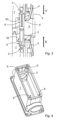
- the Figure 1 and Figure 2 show a section of a connector with a connector housing 1 and a first holding form 2 located therein. Furthermore, a fastening frame 4 of a contact insert 3 can be seen, whereby the contact insert 3 is not shown.
- the fastening frame 4 has a second holding form 5
- the holding means 6 is connected to the first holding form 2.
- the holding means 6 is essentially made up of two parts. First of all, the fixing body 60 of the holding means 6 can be seen connected to the first holding form 2.
- the fixing body 60 is essentially hollow-cylindrical.
- a fixing element 61 is arranged in the fixing body 60.
- the fixing element 61 has a head which serves as a release element 62.
- the fixing element 61 is engaged with the fixing body 60. In this way, the contact insert 3 and its fastening frame 4 of the connector housing 1 are securely held with the mating connector housing 1' and the corresponding components during the plugged-in state.
- the fixing element 61 is removed from the fixing body 60 during a release process of the connector housing 1 and mating connector housing 1', ideally after the plugging forces or tensile forces of the contact elements arranged in the contact inserts 3 and 3' have been overcome, so that the contact inserts 3 and 3' are not released together from the connector housing 1 or the mating connector housing 1'.
- FIG 4 shows a clever embodiment in which a connector housing 1 designed as a mounting housing accommodates a first holding means 6 and a second holding means 6' in the first holding forms 2 in an alternating manner.
- the arrangement shown enables a particularly advantageous fastening of the contact inserts 3 to be used, or of the fastening frames 4 located thereon.
- Alternative arrangements of the holding means 6 and 6' are conceivable for coding purposes.
Landscapes
- Connector Housings Or Holding Contact Members (AREA)
Applications Claiming Priority (1)
| Application Number | Priority Date | Filing Date | Title |
|---|---|---|---|
| DE102023118586.1A DE102023118586A1 (de) | 2023-07-13 | 2023-07-13 | Steckverbinder mit Kontakteinsatzbefestigung |
Publications (1)
| Publication Number | Publication Date |
|---|---|
| EP4492586A1 true EP4492586A1 (fr) | 2025-01-15 |
Family
ID=91782182
Family Applications (1)
| Application Number | Title | Priority Date | Filing Date |
|---|---|---|---|
| EP24000086.9A Pending EP4492586A1 (fr) | 2023-07-13 | 2024-07-01 | Connecteur enfichable avec fixation d'insert de contact |
Country Status (4)
| Country | Link |
|---|---|
| US (1) | US20250023295A1 (fr) |
| EP (1) | EP4492586A1 (fr) |
| CN (1) | CN119315318A (fr) |
| DE (1) | DE102023118586A1 (fr) |
Citations (5)
| Publication number | Priority date | Publication date | Assignee | Title |
|---|---|---|---|---|
| DE19707120C1 (de) | 1997-02-22 | 1998-06-25 | Harting Kgaa | Halterahmen |
| WO2009114194A2 (fr) * | 2008-03-14 | 2009-09-17 | Tyco Electronics Corporation | Module d’interface |
| WO2021160657A1 (fr) * | 2020-02-14 | 2021-08-19 | Phoenix Contact Gmbh & Co. Kg | Ensemble de pièce de connecteur enfichable, pièce de connecteur enfichable et dispositif électronique |
| DE102020126486A1 (de) * | 2020-10-09 | 2022-04-14 | Phoenix Contact Gmbh & Co. Kg | Halterahmen für einen Steckverbinder |
| DE102015017352B3 (de) * | 2015-10-27 | 2022-11-24 | Phoenix Contact Gmbh & Co. Kg | Baugruppe eines Steckverbinderteils mit einem Halterahmen zum Aufnehmen von modularen Kontakteinsätzen |
Family Cites Families (2)
| Publication number | Priority date | Publication date | Assignee | Title |
|---|---|---|---|---|
| DE10303800B3 (de) * | 2003-01-31 | 2004-06-03 | Harting Electric Gmbh & Co. Kg | Einrichtung zur Befestigung eines Steckverbinderkontakteinsatzes in einem Steckverbindergehäuse |
| US8668530B2 (en) * | 2009-12-09 | 2014-03-11 | Harting Electric Gmbh & Co. Kg | System plug connector |
-
2023
- 2023-07-13 DE DE102023118586.1A patent/DE102023118586A1/de active Pending
-
2024
- 2024-07-01 EP EP24000086.9A patent/EP4492586A1/fr active Pending
- 2024-07-11 US US18/769,419 patent/US20250023295A1/en active Pending
- 2024-07-12 CN CN202410933574.8A patent/CN119315318A/zh active Pending
Patent Citations (5)
| Publication number | Priority date | Publication date | Assignee | Title |
|---|---|---|---|---|
| DE19707120C1 (de) | 1997-02-22 | 1998-06-25 | Harting Kgaa | Halterahmen |
| WO2009114194A2 (fr) * | 2008-03-14 | 2009-09-17 | Tyco Electronics Corporation | Module d’interface |
| DE102015017352B3 (de) * | 2015-10-27 | 2022-11-24 | Phoenix Contact Gmbh & Co. Kg | Baugruppe eines Steckverbinderteils mit einem Halterahmen zum Aufnehmen von modularen Kontakteinsätzen |
| WO2021160657A1 (fr) * | 2020-02-14 | 2021-08-19 | Phoenix Contact Gmbh & Co. Kg | Ensemble de pièce de connecteur enfichable, pièce de connecteur enfichable et dispositif électronique |
| DE102020126486A1 (de) * | 2020-10-09 | 2022-04-14 | Phoenix Contact Gmbh & Co. Kg | Halterahmen für einen Steckverbinder |
Also Published As
| Publication number | Publication date |
|---|---|
| CN119315318A (zh) | 2025-01-14 |
| DE102023118586A1 (de) | 2025-01-16 |
| US20250023295A1 (en) | 2025-01-16 |
Similar Documents
| Publication | Publication Date | Title |
|---|---|---|
| DE102007026582B3 (de) | Steckverbindergehäuse mit einer Fixierung für ein elektrisches Kontaktelement und eine elektrische Leitung | |
| DE102015114703A1 (de) | Halterahmen für Steckverbindermodule | |
| EP3735722B1 (fr) | Support de contact et connecteur pour un agencement de contacts hybride blindé | |
| DE102020103896B4 (de) | Anbaugehäuse für Steckverbindungen und Steckverbindersystem | |
| DE202009005366U1 (de) | Industrie-Steckvorrichtung | |
| DE102004056945B4 (de) | Hebelverschluss-Steckerverbindung | |
| EP4416801B1 (fr) | Module de connecteur et son procédé de production | |
| DE102014110279B3 (de) | Steckverbinder | |
| WO2025223614A1 (fr) | Module adaptateur pour connecteur industriel modulaire | |
| DE102022117323B4 (de) | Steckverbindung mit Sekundärverriegelung | |
| DE102016121577A1 (de) | Montagewerkzeug für eine Steckerverbindung | |
| DE102023118586A1 (de) | Steckverbinder mit Kontakteinsatzbefestigung | |
| EP4699191A1 (fr) | Système de fiches de connexion haute puissance | |
| WO2024061406A1 (fr) | Élément de contact électrique, insert de connecteur enfichable et connecteur enfichable industriel modulaire le comprenant | |
| DE102021133010A1 (de) | Modularer Steckverbinder | |
| EP4492585A1 (fr) | Connecteur enfichable avec fixation d'insert de contact | |
| WO2022007994A1 (fr) | Module de transmission de données | |
| DE2734333A1 (de) | Verbindungsgehaeuse | |
| DE202010011497U1 (de) | Anschlussdose mit Halteeinrichtung für Steckverbinder | |
| WO2025124633A1 (fr) | Cadre de maintien pour connecteur enfichable industriel modulaire | |
| WO2025021299A1 (fr) | Connexion enfichable ayant un mécanisme de verrouillage secondaire | |
| DE102021129501A1 (de) | Elektrischer Rundsteckverbinder mit Isolierkörper und Kontaktelementsicherung | |
| DE102022105337A1 (de) | Kontakteinsatz mit Brückungsfunktion für einen Industriesteckverbinder | |
| DE102023113561A1 (de) | Modularer Industriesteckverbinder | |
| EP4546575A1 (fr) | Boîtier de montage avec joint d'étanchéité |
Legal Events
| Date | Code | Title | Description |
|---|---|---|---|
| PUAI | Public reference made under article 153(3) epc to a published international application that has entered the european phase |
Free format text: ORIGINAL CODE: 0009012 |
|
| STAA | Information on the status of an ep patent application or granted ep patent |
Free format text: STATUS: THE APPLICATION HAS BEEN PUBLISHED |
|
| AK | Designated contracting states |
Kind code of ref document: A1 Designated state(s): AL AT BE BG CH CY CZ DE DK EE ES FI FR GB GR HR HU IE IS IT LI LT LU LV MC ME MK MT NL NO PL PT RO RS SE SI SK SM TR |
|
| STAA | Information on the status of an ep patent application or granted ep patent |
Free format text: STATUS: REQUEST FOR EXAMINATION WAS MADE |
|
| 17P | Request for examination filed |
Effective date: 20250715 |
|
| GRAP | Despatch of communication of intention to grant a patent |
Free format text: ORIGINAL CODE: EPIDOSNIGR1 |
|
| STAA | Information on the status of an ep patent application or granted ep patent |
Free format text: STATUS: GRANT OF PATENT IS INTENDED |
|
| INTG | Intention to grant announced |
Effective date: 20260702 |