EP4492647A1 - Schwungradvorrichtung und elektrische drehmaschine - Google Patents
Schwungradvorrichtung und elektrische drehmaschine Download PDFInfo
- Publication number
- EP4492647A1 EP4492647A1 EP22942959.2A EP22942959A EP4492647A1 EP 4492647 A1 EP4492647 A1 EP 4492647A1 EP 22942959 A EP22942959 A EP 22942959A EP 4492647 A1 EP4492647 A1 EP 4492647A1
- Authority
- EP
- European Patent Office
- Prior art keywords
- magnets
- cylindrical members
- members
- rotation shaft
- axis direction
- Prior art date
- Legal status (The legal status is an assumption and is not a legal conclusion. Google has not performed a legal analysis and makes no representation as to the accuracy of the status listed.)
- Pending
Links
Images


Classifications
-
- H—ELECTRICITY
- H02—GENERATION; CONVERSION OR DISTRIBUTION OF ELECTRIC POWER
- H02K—DYNAMO-ELECTRIC MACHINES
- H02K7/00—Arrangements for handling mechanical energy structurally associated with dynamo-electric machines, e.g. structural association with mechanical driving motors or auxiliary dynamo-electric machines
- H02K7/04—Balancing means
-
- F—MECHANICAL ENGINEERING; LIGHTING; HEATING; WEAPONS; BLASTING
- F16—ENGINEERING ELEMENTS AND UNITS; GENERAL MEASURES FOR PRODUCING AND MAINTAINING EFFECTIVE FUNCTIONING OF MACHINES OR INSTALLATIONS; THERMAL INSULATION IN GENERAL
- F16C—SHAFTS; FLEXIBLE SHAFTS; ELEMENTS OR CRANKSHAFT MECHANISMS; ROTARY BODIES OTHER THAN GEARING ELEMENTS; BEARINGS
- F16C32/00—Bearings not otherwise provided for
- F16C32/04—Bearings not otherwise provided for using magnetic or electric supporting means
- F16C32/0406—Magnetic bearings
- F16C32/0408—Passive magnetic bearings
- F16C32/0423—Passive magnetic bearings with permanent magnets on both parts repelling each other
- F16C32/0425—Passive magnetic bearings with permanent magnets on both parts repelling each other for radial load mainly
-
- H—ELECTRICITY
- H02—GENERATION; CONVERSION OR DISTRIBUTION OF ELECTRIC POWER
- H02K—DYNAMO-ELECTRIC MACHINES
- H02K7/00—Arrangements for handling mechanical energy structurally associated with dynamo-electric machines, e.g. structural association with mechanical driving motors or auxiliary dynamo-electric machines
- H02K7/02—Additional mass for increasing inertia, e.g. flywheels
- H02K7/025—Additional mass for increasing inertia, e.g. flywheels for power storage
-
- H—ELECTRICITY
- H02—GENERATION; CONVERSION OR DISTRIBUTION OF ELECTRIC POWER
- H02K—DYNAMO-ELECTRIC MACHINES
- H02K7/00—Arrangements for handling mechanical energy structurally associated with dynamo-electric machines, e.g. structural association with mechanical driving motors or auxiliary dynamo-electric machines
- H02K7/08—Structural association with bearings
- H02K7/09—Structural association with bearings with magnetic bearings
-
- H—ELECTRICITY
- H02—GENERATION; CONVERSION OR DISTRIBUTION OF ELECTRIC POWER
- H02K—DYNAMO-ELECTRIC MACHINES
- H02K2213/00—Specific aspects, not otherwise provided for and not covered by codes H02K2201/00 - H02K2211/00
- H02K2213/03—Machines characterised by numerical values, ranges, mathematical expressions or similar information
-
- Y—GENERAL TAGGING OF NEW TECHNOLOGICAL DEVELOPMENTS; GENERAL TAGGING OF CROSS-SECTIONAL TECHNOLOGIES SPANNING OVER SEVERAL SECTIONS OF THE IPC; TECHNICAL SUBJECTS COVERED BY FORMER USPC CROSS-REFERENCE ART COLLECTIONS [XRACs] AND DIGESTS
- Y02—TECHNOLOGIES OR APPLICATIONS FOR MITIGATION OR ADAPTATION AGAINST CLIMATE CHANGE
- Y02E—REDUCTION OF GREENHOUSE GAS [GHG] EMISSIONS, RELATED TO ENERGY GENERATION, TRANSMISSION OR DISTRIBUTION
- Y02E60/00—Enabling technologies; Technologies with a potential or indirect contribution to GHG emissions mitigation
- Y02E60/16—Mechanical energy storage, e.g. flywheels or pressurised fluids
Definitions
- the present invention relates to a flywheel device and a rotating electric machine.
- a generator rotates a rotor inside a stator fixed to a support, thereby generating induced electromotive force to generate electric power.
- the rotational movement of the rotor is caused by torque resulting from, for example, hydraulic power, thermal power, atomic power, or an internal combustion engine such as a diesel engine.
- magnetic bearings using permanent magnets are effective in that the magnetic bearings can support rotation of the rotor without consuming electric power unnecessarily, compared with magnetic bearings using electromagnets.
- an object of the present invention is to provide a flywheel device that effects stable rotation in which not only friction in a circumference direction (radial direction), but also friction in an axis direction (axial direction) movement are suppressed without being generated, and that maintains rotational energy for a longer time.
- a flywheel device comprising:
- another embodiment of the present invention relates to a rotating electric machine including the above-described flywheel device, a rotor fixed to the rotation shaft in middle of the pair of disk members, and a stator disposed on the support body.
- a flywheel device can be provided that effects stable rotation in which not only friction in a circumference direction (radial direction), but also friction in an axis direction (axial direction) movement are suppressed without being generated, and that maintains rotational energy for a longer time.
- FIG. 1 and Figure 2 are a front view and a cross-sectional view respectively for describing a flywheel device 100 according to a first embodiment.
- the flywheel device 100 includes a support body 10, a rotation shaft 20, a pair of disk members 30 spaced from each other and fixed on the rotation shaft 20, a pair of inner cylindrical members 40 that are connected to the outer circumferences of the disk members 30, respectively, and that are formed coaxially with the rotation shaft 20, and a pair of outer cylindrical members 50 that are arranged to the support body 10 so as to face the outer circumferences of the inner cylindrical members 40, respectively, and that are provided away from the outer circumferences of the inner cylindrical members 40.
- a direction parallel to the rotation shaft 20 is referred to as an axis direction or an axial direction
- a direction perpendicular to the rotation shaft 20 and toward the circumference direction of the disk members 30 is referred to as a circumference direction or a radial direction
- a direction in which the pair of disk members 30 approach to each other toward a symmetry plane is referred to as "inward” in a thrust direction or an inner direction
- a direction in which the pair of disk members 30 move away from each other is referred to as "outward" in the thrust direction or an outer direction.
- the support body 10 is a structure that is provided with the outer cylindrical member 50, which will be described later, and that supports the other members of the flywheel device 100 in a non-contact manner.
- the support body 10 may be further provided with a stator 80 of a rotating electric machine 300 as will be describe later.
- the support body 10 may have any kind of shape and may be made of any kind of material, as long as the support body 10 has a strength capable of meeting the magnetic repulsive force applied to the outer cylindrical member 50.
- soft magnetic materials such as iron, silicon steel, permalloy, and sendust
- non-magnetic materials such as carbon and wood can be used.
- the rotation shaft 20 is a shaft that is provided with the pair of disk members 30 thereon with the rotation shaft 20 as the center, and that serves as a central axis of the rotation of the pair of disk members 30.
- the rotation shaft 20 is also provided with a rotor 70 of the rotating electric machine 300 as will be describe later, and the rotor 70 can be rotated with the rotation of the rotation shaft 20.
- the disk members 30 are a pair of circular members that has the rotation shaft 20 as the center of their circles, and that are spaced apart and provided on the rotation shaft 20.
- the disk members 30 have a large area with respect to the cross-sectional area of the rotation shaft 20.
- the disk members 30 are preferably lightweight, and preferably have a hollow structure. Additionally, the disk members 30 preferably has a smaller width in the axis direction compared with the inner cylindrical members 40.
- the inner cylindrical members 40 are members that are connected to the outer circumferences of the disk members 30, respectively, and that are formed coaxially with the rotation shaft 20.
- the inner cylindrical members 40 are formed by continuous inner magnets 45 in the circumferential direction, having magnetic poles on outer peripheral surfaces thereof.
- the inner magnets 45 preferably form a cylinder shape.
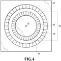
- the inner magnets 45 may be formed by an integral-type cylinder-shaped magnet (refer to Figure 1 ), or may be formed by arranging divided magnets in a cylinder shape so that the magnetic poles of the outer peripheral surfaces thereof become the same (refer to Figure 4 ).
- the magnets used for the inner magnets 45 are preferably permanent magnets with strong magnetic force, and for example, rare earth magnets such as neodymium magnets and samarium cobalt magnets, ferritic magnets, and the like can be used.
- the inner cylindrical members 40 constitute a flywheel 60 together with the disk members 30, and can maintain the rotational energy for a longer period due to the moment of inertia.
- the mass of the inner cylindrical members 40 is larger, and the mass of the disk members 30 is more lightweight.
- the outer cylindrical members 50 are arranged to the support body 10 so as to face the outer circumferences of the inner cylindrical members 40, respectively, and are provided away from the outer circumferences of the inner cylindrical members 40.
- outer magnets 55 facing the inner magnets 45 with the same polarity facing each other are continuously formed in the circumference direction.
- the outer magnets 55 preferably form a cylinder shape. Similar to the inner magnets 45, the outer magnets 55 may be formed with an integral-type cylinder-shaped magnet (refer to Figure 1 ), or may be formed by arranging divided magnets in a cylinder shape so that the magnetic poles of the outer peripheral surfaces thereof become the same (refer to Figure 4 ).
- the magnets used for the outer magnets 55 are preferably permanent magnets with strong magnetic force, and for example, rare earth magnets such as neodymium magnets and samarium cobalt magnets, ferrite magnets, and the like can be used.
- centers 46 of the widths of the inner magnets 45 in the axis direction are offset from centers 56 of the widths of the outer magnet 55 in the axis direction, respectively.
- each of the width centers 46 of the inner magnets 45 is offset from each of the width centers 56 of the outer magnet 55 inward in the thrust direction (in a mutually approaching direction in the axis direction), or outward in the thrust direction (in a direction away from each other).
- the flywheel device 100 according to the first embodiment of the present invention illustrated in Figure 2 shows a structure in which each of the width centers 46 of the inner magnets 45 is offset from each of the width centers 56 of the outer magnets 55 inward in the thrust direction.
- radial repulsive force an arrow R
- thrust repulsive force an arrow S
- the flywheel 60 can be maintained in a non-contact state both in the radial direction and the axial direction by the outer magnets 55.
- the flywheel 60 can also have, in addition to the original function as a flywheel, a function of reducing friction that occurs at the time of rotation by floating and supporting the rotation shaft 20 including the rotor 70 with the magnetic repulsive force, as a magnetic bearing. That is, since the force acting on the bearing of one embodiment of the present invention is repulsive force, the rotation shaft 20 can be held at a position where magnetic forces are balanced, without requiring complicated control.
- the flywheel function and the magnetic bearing functions are integrated, the size of the device can be reduced.
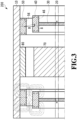
- FIG. 3 illustrates a flywheel device 200 according to a second embodiment of the present invention.
- the flywheel device 200 has a structure in which each of the width centers 46 of the inner magnets 45 is offset from each of the width centers 56 of the outer magnets 55 outward in the thrust direction. Also in this case, the radial repulsive force (the arrow R) and the thrust repulsive force (the arrow S) are generated between the width center 46 of the inner magnet 45 and the width center 56 of the outer magnet 55. Then, when one flywheel 60 tends to move outward in the thrust direction, the thrust repulsive force between the other flywheel 60 and the outer magnet 55 facing therewith increases, and movement in the thrust direction can also be suppressed.
- the flywheel 60 can maintain a stable position in a non-contact state both in the radial direction and the axial direction by the outer magnets 55, can provide stable rotation without generating friction, and can maintain rotational energy for a longer time.
- a third embodiment of the present invention relates to a rotating electric machine 300 including the above-described flywheel device.
- the rotating electric machine 300 includes the above-described flywheel device 100 or 200 of the present invention, and has the rotor 70 fixed to the rotation shaft 20 and the stator 80 disposed on the support body 10 in the middle of the pair of disk members 30.
- the rotating electric machine 300 can be used as a generator or a motor.
- a part of the rotor 70 may directly contact, or a terminal portion (not illustrated) electrically connected from the rotor 70 may contact an external terminal such as a brush.
Landscapes
- Engineering & Computer Science (AREA)
- Power Engineering (AREA)
- General Engineering & Computer Science (AREA)
- Mechanical Engineering (AREA)
- Magnetic Bearings And Hydrostatic Bearings (AREA)
- Connection Of Motors, Electrical Generators, Mechanical Devices, And The Like (AREA)
Applications Claiming Priority (1)
| Application Number | Priority Date | Filing Date | Title |
|---|---|---|---|
| PCT/JP2022/021287 WO2023228285A1 (ja) | 2022-05-24 | 2022-05-24 | フライホイール装置および回転電機 |
Publications (2)
| Publication Number | Publication Date |
|---|---|
| EP4492647A1 true EP4492647A1 (de) | 2025-01-15 |
| EP4492647A4 EP4492647A4 (de) | 2025-12-10 |
Family
ID=88918631
Family Applications (1)
| Application Number | Title | Priority Date | Filing Date |
|---|---|---|---|
| EP22942959.2A Pending EP4492647A4 (de) | 2022-05-24 | 2022-05-24 | Schwungradvorrichtung und elektrische drehmaschine |
Country Status (6)
| Country | Link |
|---|---|
| US (1) | US20250246969A1 (de) |
| EP (1) | EP4492647A4 (de) |
| JP (1) | JP7816816B2 (de) |
| CN (1) | CN117461246A (de) |
| TW (1) | TWI910431B (de) |
| WO (1) | WO2023228285A1 (de) |
Family Cites Families (5)
| Publication number | Priority date | Publication date | Assignee | Title |
|---|---|---|---|---|
| JPS5227297B2 (de) * | 1971-09-27 | 1977-07-19 | ||
| JPS5612831A (en) * | 1979-07-09 | 1981-02-07 | Nakano Bussan Kk | Tubular potary electric machine |
| JP3138696B2 (ja) | 1998-03-12 | 2001-02-26 | 日本電産コパル電子株式会社 | 軸受構造 |
| JP2007092646A (ja) * | 2005-09-29 | 2007-04-12 | Jtekt Corp | 燃料電池用過給機 |
| JP7064728B2 (ja) * | 2018-06-28 | 2022-05-11 | 株式会社ナカダクリエイト | フライホイール装置及び回転電機 |
-
2022
- 2022-05-24 WO PCT/JP2022/021287 patent/WO2023228285A1/ja not_active Ceased
- 2022-05-24 JP JP2024522768A patent/JP7816816B2/ja active Active
- 2022-05-24 EP EP22942959.2A patent/EP4492647A4/de active Pending
- 2022-05-24 US US18/855,097 patent/US20250246969A1/en active Pending
- 2022-05-24 CN CN202280040329.3A patent/CN117461246A/zh active Pending
-
2023
- 2023-05-23 TW TW112119122A patent/TWI910431B/zh active
Also Published As
| Publication number | Publication date |
|---|---|
| EP4492647A4 (de) | 2025-12-10 |
| US20250246969A1 (en) | 2025-07-31 |
| CN117461246A (zh) | 2024-01-26 |
| JPWO2023228285A1 (de) | 2023-11-30 |
| TWI910431B (zh) | 2026-01-01 |
| TW202346732A (zh) | 2023-12-01 |
| WO2023228285A1 (ja) | 2023-11-30 |
| JP7816816B2 (ja) | 2026-02-18 |
Similar Documents
| Publication | Publication Date | Title |
|---|---|---|
| JP3850195B2 (ja) | 磁気浮上モータ | |
| JPS61124255A (ja) | 回転駆動装置 | |
| JPH08178011A (ja) | フライホイール装置 | |
| US6369477B1 (en) | Roller-type electric motor | |
| EP3017529B1 (de) | Reduzierung der lagerkräfte bei einer elektrischen maschine | |
| US20250246969A1 (en) | Flywheel device and rotary electric machine | |
| JP7195923B2 (ja) | 回転電機 | |
| JPWO2017158710A1 (ja) | フライホイール装置及び回転電機 | |
| CN111173838A (zh) | 径向无耦合三自由度直流混合磁轴承 | |
| JP2016039733A (ja) | フライホイール装置及び、発電及び駆動モータ装置 | |
| JP2018157755A (ja) | フライホイール装置及び、発電及び駆動モータ装置 | |
| JP7064728B2 (ja) | フライホイール装置及び回転電機 | |
| JP3215881U (ja) | フライホイール装置及び回転電機 | |
| JP7470470B1 (ja) | 発電システム | |
| JP2018078801A (ja) | 回転電機 | |
| JP2026075331A (ja) | ロータ | |
| KR102803892B1 (ko) | 고효율 고출력 요크리스 이중 로터 모터 및 발전기 | |
| KR102803325B1 (ko) | Halbach Array 배열을 가지는 요크리스 이중 로터 모터 | |
| JPH11257354A (ja) | 磁気軸受用回転子および超伝導磁気軸受 | |
| RU2807680C2 (ru) | Электрическая машина с дополнительным подвижным самонаправляющимся статором | |
| JP2012170264A (ja) | 磁気歯車装置 | |
| RU2650178C1 (ru) | Двигатель-маховик | |
| JPH0135578Y2 (de) | ||
| JPS6275124A (ja) | 磁気軸受装置 | |
| JPH11243681A (ja) | 磁場力エンジン |
Legal Events
| Date | Code | Title | Description |
|---|---|---|---|
| STAA | Information on the status of an ep patent application or granted ep patent |
Free format text: STATUS: THE INTERNATIONAL PUBLICATION HAS BEEN MADE |
|
| PUAI | Public reference made under article 153(3) epc to a published international application that has entered the european phase |
Free format text: ORIGINAL CODE: 0009012 |
|
| STAA | Information on the status of an ep patent application or granted ep patent |
Free format text: STATUS: REQUEST FOR EXAMINATION WAS MADE |
|
| 17P | Request for examination filed |
Effective date: 20241008 |
|
| AK | Designated contracting states |
Kind code of ref document: A1 Designated state(s): AL AT BE BG CH CY CZ DE DK EE ES FI FR GB GR HR HU IE IS IT LI LT LU LV MC MK MT NL NO PL PT RO RS SE SI SK SM TR |
|
| DAV | Request for validation of the european patent (deleted) | ||
| DAX | Request for extension of the european patent (deleted) | ||
| A4 | Supplementary search report drawn up and despatched |
Effective date: 20251111 |
|
| RIC1 | Information provided on ipc code assigned before grant |
Ipc: H02K 7/02 20060101AFI20251105BHEP Ipc: H02K 7/09 20060101ALI20251105BHEP |