EP4492663A1 - Circuit d'aspiration pour un convertisseur de traction d'un véhicule ferroviaire - Google Patents
Circuit d'aspiration pour un convertisseur de traction d'un véhicule ferroviaire Download PDFInfo
- Publication number
- EP4492663A1 EP4492663A1 EP24181114.0A EP24181114A EP4492663A1 EP 4492663 A1 EP4492663 A1 EP 4492663A1 EP 24181114 A EP24181114 A EP 24181114A EP 4492663 A1 EP4492663 A1 EP 4492663A1
- Authority
- EP
- European Patent Office
- Prior art keywords
- switching
- switching unit
- circuit arrangement
- arrangement
- voltage
- Prior art date
- Legal status (The legal status is an assumption and is not a legal conclusion. Google has not performed a legal analysis and makes no representation as to the accuracy of the status listed.)
- Pending
Links
Images


Classifications
-
- H—ELECTRICITY
- H02—GENERATION; CONVERSION OR DISTRIBUTION OF ELECTRIC POWER
- H02M—APPARATUS FOR CONVERSION BETWEEN AC AND AC, BETWEEN AC AND DC, OR BETWEEN DC AND DC, AND FOR USE WITH MAINS OR SIMILAR POWER SUPPLY SYSTEMS; CONVERSION OF DC OR AC INPUT POWER INTO SURGE OUTPUT POWER; CONTROL OR REGULATION THEREOF
- H02M1/00—Details of apparatus for conversion
- H02M1/14—Arrangements for reducing ripples from DC input or output
- H02M1/15—Arrangements for reducing ripples from DC input or output using active elements
-
- B—PERFORMING OPERATIONS; TRANSPORTING
- B60—VEHICLES IN GENERAL
- B60L—PROPULSION OF ELECTRICALLY-PROPELLED VEHICLES; SUPPLYING ELECTRIC POWER FOR AUXILIARY EQUIPMENT OF ELECTRICALLY-PROPELLED VEHICLES; ELECTRODYNAMIC BRAKE SYSTEMS FOR VEHICLES IN GENERAL; MAGNETIC SUSPENSION OR LEVITATION FOR VEHICLES; MONITORING OPERATING VARIABLES OF ELECTRICALLY-PROPELLED VEHICLES; ELECTRIC SAFETY DEVICES FOR ELECTRICALLY-PROPELLED VEHICLES
- B60L9/00—Electric propulsion with power supply external to the vehicle
-
- B—PERFORMING OPERATIONS; TRANSPORTING
- B60—VEHICLES IN GENERAL
- B60L—PROPULSION OF ELECTRICALLY-PROPELLED VEHICLES; SUPPLYING ELECTRIC POWER FOR AUXILIARY EQUIPMENT OF ELECTRICALLY-PROPELLED VEHICLES; ELECTRODYNAMIC BRAKE SYSTEMS FOR VEHICLES IN GENERAL; MAGNETIC SUSPENSION OR LEVITATION FOR VEHICLES; MONITORING OPERATING VARIABLES OF ELECTRICALLY-PROPELLED VEHICLES; ELECTRIC SAFETY DEVICES FOR ELECTRICALLY-PROPELLED VEHICLES
- B60L3/00—Electric devices on electrically-propelled vehicles for safety purposes; Monitoring operating variables, e.g. speed, deceleration or energy consumption
- B60L3/0023—Detecting, eliminating, remedying or compensating for drive train abnormalities, e.g. failures within the drive train
- B60L3/003—Detecting, eliminating, remedying or compensating for drive train abnormalities, e.g. failures within the drive train relating to inverters
-
- B—PERFORMING OPERATIONS; TRANSPORTING
- B60—VEHICLES IN GENERAL
- B60L—PROPULSION OF ELECTRICALLY-PROPELLED VEHICLES; SUPPLYING ELECTRIC POWER FOR AUXILIARY EQUIPMENT OF ELECTRICALLY-PROPELLED VEHICLES; ELECTRODYNAMIC BRAKE SYSTEMS FOR VEHICLES IN GENERAL; MAGNETIC SUSPENSION OR LEVITATION FOR VEHICLES; MONITORING OPERATING VARIABLES OF ELECTRICALLY-PROPELLED VEHICLES; ELECTRIC SAFETY DEVICES FOR ELECTRICALLY-PROPELLED VEHICLES
- B60L50/00—Electric propulsion with power supplied within the vehicle
- B60L50/50—Electric propulsion with power supplied within the vehicle using propulsion power supplied by batteries or fuel cells
- B60L50/53—Electric propulsion with power supplied within the vehicle using propulsion power supplied by batteries or fuel cells in combination with an external power supply, e.g. from overhead contact lines
-
- B—PERFORMING OPERATIONS; TRANSPORTING
- B60—VEHICLES IN GENERAL
- B60L—PROPULSION OF ELECTRICALLY-PROPELLED VEHICLES; SUPPLYING ELECTRIC POWER FOR AUXILIARY EQUIPMENT OF ELECTRICALLY-PROPELLED VEHICLES; ELECTRODYNAMIC BRAKE SYSTEMS FOR VEHICLES IN GENERAL; MAGNETIC SUSPENSION OR LEVITATION FOR VEHICLES; MONITORING OPERATING VARIABLES OF ELECTRICALLY-PROPELLED VEHICLES; ELECTRIC SAFETY DEVICES FOR ELECTRICALLY-PROPELLED VEHICLES
- B60L53/00—Methods of charging batteries, specially adapted for electric vehicles; Charging stations or on-board charging equipment therefor; Exchange of energy storage elements in electric vehicles
- B60L53/20—Methods of charging batteries, specially adapted for electric vehicles; Charging stations or on-board charging equipment therefor; Exchange of energy storage elements in electric vehicles characterised by converters located in the vehicle
- B60L53/24—Using the vehicle's propulsion converter for charging
-
- H—ELECTRICITY
- H02—GENERATION; CONVERSION OR DISTRIBUTION OF ELECTRIC POWER
- H02M—APPARATUS FOR CONVERSION BETWEEN AC AND AC, BETWEEN AC AND DC, OR BETWEEN DC AND DC, AND FOR USE WITH MAINS OR SIMILAR POWER SUPPLY SYSTEMS; CONVERSION OF DC OR AC INPUT POWER INTO SURGE OUTPUT POWER; CONTROL OR REGULATION THEREOF
- H02M1/00—Details of apparatus for conversion
- H02M1/0048—Circuits or arrangements for reducing losses
-
- H—ELECTRICITY
- H02—GENERATION; CONVERSION OR DISTRIBUTION OF ELECTRIC POWER
- H02M—APPARATUS FOR CONVERSION BETWEEN AC AND AC, BETWEEN AC AND DC, OR BETWEEN DC AND DC, AND FOR USE WITH MAINS OR SIMILAR POWER SUPPLY SYSTEMS; CONVERSION OF DC OR AC INPUT POWER INTO SURGE OUTPUT POWER; CONTROL OR REGULATION THEREOF
- H02M1/00—Details of apparatus for conversion
- H02M1/0067—Converter structures employing plural converter units, other than for parallel operation of the units on a single load
- H02M1/007—Plural converter units in cascade
-
- H—ELECTRICITY
- H02—GENERATION; CONVERSION OR DISTRIBUTION OF ELECTRIC POWER
- H02M—APPARATUS FOR CONVERSION BETWEEN AC AND AC, BETWEEN AC AND DC, OR BETWEEN DC AND DC, AND FOR USE WITH MAINS OR SIMILAR POWER SUPPLY SYSTEMS; CONVERSION OF DC OR AC INPUT POWER INTO SURGE OUTPUT POWER; CONTROL OR REGULATION THEREOF
- H02M1/00—Details of apparatus for conversion
- H02M1/0067—Converter structures employing plural converter units, other than for parallel operation of the units on a single load
- H02M1/0077—Plural converter units whose outputs are connected in series
-
- H—ELECTRICITY
- H02—GENERATION; CONVERSION OR DISTRIBUTION OF ELECTRIC POWER
- H02M—APPARATUS FOR CONVERSION BETWEEN AC AND AC, BETWEEN AC AND DC, OR BETWEEN DC AND DC, AND FOR USE WITH MAINS OR SIMILAR POWER SUPPLY SYSTEMS; CONVERSION OF DC OR AC INPUT POWER INTO SURGE OUTPUT POWER; CONTROL OR REGULATION THEREOF
- H02M1/00—Details of apparatus for conversion
- H02M1/0083—Converters characterised by their input or output configuration
- H02M1/0093—Converters characterised by their input or output configuration wherein the output is created by adding a regulated voltage to or subtracting it from an unregulated input
-
- H—ELECTRICITY
- H02—GENERATION; CONVERSION OR DISTRIBUTION OF ELECTRIC POWER
- H02M—APPARATUS FOR CONVERSION BETWEEN AC AND AC, BETWEEN AC AND DC, OR BETWEEN DC AND DC, AND FOR USE WITH MAINS OR SIMILAR POWER SUPPLY SYSTEMS; CONVERSION OF DC OR AC INPUT POWER INTO SURGE OUTPUT POWER; CONTROL OR REGULATION THEREOF
- H02M1/00—Details of apparatus for conversion
- H02M1/0095—Hybrid converter topologies, e.g. NPC mixed with flying capacitor, thyristor converter mixed with MMC or charge pump mixed with buck
-
- H—ELECTRICITY
- H02—GENERATION; CONVERSION OR DISTRIBUTION OF ELECTRIC POWER
- H02M—APPARATUS FOR CONVERSION BETWEEN AC AND AC, BETWEEN AC AND DC, OR BETWEEN DC AND DC, AND FOR USE WITH MAINS OR SIMILAR POWER SUPPLY SYSTEMS; CONVERSION OF DC OR AC INPUT POWER INTO SURGE OUTPUT POWER; CONTROL OR REGULATION THEREOF
- H02M1/00—Details of apparatus for conversion
- H02M1/12—Arrangements for reducing harmonics from AC input or output
-
- H—ELECTRICITY
- H02—GENERATION; CONVERSION OR DISTRIBUTION OF ELECTRIC POWER
- H02M—APPARATUS FOR CONVERSION BETWEEN AC AND AC, BETWEEN AC AND DC, OR BETWEEN DC AND DC, AND FOR USE WITH MAINS OR SIMILAR POWER SUPPLY SYSTEMS; CONVERSION OF DC OR AC INPUT POWER INTO SURGE OUTPUT POWER; CONTROL OR REGULATION THEREOF
- H02M1/00—Details of apparatus for conversion
- H02M1/14—Arrangements for reducing ripples from DC input or output
-
- H—ELECTRICITY
- H02—GENERATION; CONVERSION OR DISTRIBUTION OF ELECTRIC POWER
- H02M—APPARATUS FOR CONVERSION BETWEEN AC AND AC, BETWEEN AC AND DC, OR BETWEEN DC AND DC, AND FOR USE WITH MAINS OR SIMILAR POWER SUPPLY SYSTEMS; CONVERSION OF DC OR AC INPUT POWER INTO SURGE OUTPUT POWER; CONTROL OR REGULATION THEREOF
- H02M1/00—Details of apparatus for conversion
- H02M1/32—Means for protecting converters other than automatic disconnection
-
- H—ELECTRICITY
- H02—GENERATION; CONVERSION OR DISTRIBUTION OF ELECTRIC POWER
- H02M—APPARATUS FOR CONVERSION BETWEEN AC AND AC, BETWEEN AC AND DC, OR BETWEEN DC AND DC, AND FOR USE WITH MAINS OR SIMILAR POWER SUPPLY SYSTEMS; CONVERSION OF DC OR AC INPUT POWER INTO SURGE OUTPUT POWER; CONTROL OR REGULATION THEREOF
- H02M3/00—Conversion of DC power input into DC power output
- H02M3/02—Conversion of DC power input into DC power output without intermediate conversion into AC
- H02M3/04—Conversion of DC power input into DC power output without intermediate conversion into AC by static converters
- H02M3/10—Conversion of DC power input into DC power output without intermediate conversion into AC by static converters using discharge tubes with control electrode or semiconductor devices with control electrode
- H02M3/145—Conversion of DC power input into DC power output without intermediate conversion into AC by static converters using discharge tubes with control electrode or semiconductor devices with control electrode using devices of a triode or transistor type requiring continuous application of a control signal
- H02M3/155—Conversion of DC power input into DC power output without intermediate conversion into AC by static converters using discharge tubes with control electrode or semiconductor devices with control electrode using devices of a triode or transistor type requiring continuous application of a control signal using semiconductor devices only
- H02M3/156—Conversion of DC power input into DC power output without intermediate conversion into AC by static converters using discharge tubes with control electrode or semiconductor devices with control electrode using devices of a triode or transistor type requiring continuous application of a control signal using semiconductor devices only with automatic control of output voltage or current, e.g. switching regulators
- H02M3/158—Conversion of DC power input into DC power output without intermediate conversion into AC by static converters using discharge tubes with control electrode or semiconductor devices with control electrode using devices of a triode or transistor type requiring continuous application of a control signal using semiconductor devices only with automatic control of output voltage or current, e.g. switching regulators including plural semiconductor devices as final control devices for a single load
-
- H—ELECTRICITY
- H02—GENERATION; CONVERSION OR DISTRIBUTION OF ELECTRIC POWER
- H02M—APPARATUS FOR CONVERSION BETWEEN AC AND AC, BETWEEN AC AND DC, OR BETWEEN DC AND DC, AND FOR USE WITH MAINS OR SIMILAR POWER SUPPLY SYSTEMS; CONVERSION OF DC OR AC INPUT POWER INTO SURGE OUTPUT POWER; CONTROL OR REGULATION THEREOF
- H02M7/00—Conversion of AC power input into DC power output; Conversion of DC power input into AC power output
- H02M7/42—Conversion of DC power input into AC power output without possibility of reversal
- H02M7/44—Conversion of DC power input into AC power output without possibility of reversal by static converters
- H02M7/48—Conversion of DC power input into AC power output without possibility of reversal by static converters using discharge tubes with control electrode or semiconductor devices with control electrode
- H02M7/483—Converters with outputs that each can have more than two voltages levels
- H02M7/4835—Converters with outputs that each can have more than two voltages levels comprising two or more cells, each including a switchable capacitor, the capacitors having a nominal charge voltage which corresponds to a given fraction of the input voltage, and the capacitors being selectively connected in series to determine the instantaneous output voltage
-
- H—ELECTRICITY
- H02—GENERATION; CONVERSION OR DISTRIBUTION OF ELECTRIC POWER
- H02M—APPARATUS FOR CONVERSION BETWEEN AC AND AC, BETWEEN AC AND DC, OR BETWEEN DC AND DC, AND FOR USE WITH MAINS OR SIMILAR POWER SUPPLY SYSTEMS; CONVERSION OF DC OR AC INPUT POWER INTO SURGE OUTPUT POWER; CONTROL OR REGULATION THEREOF
- H02M7/00—Conversion of AC power input into DC power output; Conversion of DC power input into AC power output
- H02M7/42—Conversion of DC power input into AC power output without possibility of reversal
- H02M7/44—Conversion of DC power input into AC power output without possibility of reversal by static converters
- H02M7/48—Conversion of DC power input into AC power output without possibility of reversal by static converters using discharge tubes with control electrode or semiconductor devices with control electrode
- H02M7/53—Conversion of DC power input into AC power output without possibility of reversal by static converters using discharge tubes with control electrode or semiconductor devices with control electrode using devices of a triode or transistor type requiring continuous application of a control signal
- H02M7/537—Conversion of DC power input into AC power output without possibility of reversal by static converters using discharge tubes with control electrode or semiconductor devices with control electrode using devices of a triode or transistor type requiring continuous application of a control signal using semiconductor devices only, e.g. single switched pulse inverters
- H02M7/5387—Conversion of DC power input into AC power output without possibility of reversal by static converters using discharge tubes with control electrode or semiconductor devices with control electrode using devices of a triode or transistor type requiring continuous application of a control signal using semiconductor devices only, e.g. single switched pulse inverters in a bridge configuration
-
- B—PERFORMING OPERATIONS; TRANSPORTING
- B60—VEHICLES IN GENERAL
- B60L—PROPULSION OF ELECTRICALLY-PROPELLED VEHICLES; SUPPLYING ELECTRIC POWER FOR AUXILIARY EQUIPMENT OF ELECTRICALLY-PROPELLED VEHICLES; ELECTRODYNAMIC BRAKE SYSTEMS FOR VEHICLES IN GENERAL; MAGNETIC SUSPENSION OR LEVITATION FOR VEHICLES; MONITORING OPERATING VARIABLES OF ELECTRICALLY-PROPELLED VEHICLES; ELECTRIC SAFETY DEVICES FOR ELECTRICALLY-PROPELLED VEHICLES
- B60L2200/00—Type of vehicles
- B60L2200/26—Rail vehicles
-
- B—PERFORMING OPERATIONS; TRANSPORTING
- B60—VEHICLES IN GENERAL
- B60L—PROPULSION OF ELECTRICALLY-PROPELLED VEHICLES; SUPPLYING ELECTRIC POWER FOR AUXILIARY EQUIPMENT OF ELECTRICALLY-PROPELLED VEHICLES; ELECTRODYNAMIC BRAKE SYSTEMS FOR VEHICLES IN GENERAL; MAGNETIC SUSPENSION OR LEVITATION FOR VEHICLES; MONITORING OPERATING VARIABLES OF ELECTRICALLY-PROPELLED VEHICLES; ELECTRIC SAFETY DEVICES FOR ELECTRICALLY-PROPELLED VEHICLES
- B60L2200/00—Type of vehicles
- B60L2200/30—Trolleys
-
- H—ELECTRICITY
- H02—GENERATION; CONVERSION OR DISTRIBUTION OF ELECTRIC POWER
- H02M—APPARATUS FOR CONVERSION BETWEEN AC AND AC, BETWEEN AC AND DC, OR BETWEEN DC AND DC, AND FOR USE WITH MAINS OR SIMILAR POWER SUPPLY SYSTEMS; CONVERSION OF DC OR AC INPUT POWER INTO SURGE OUTPUT POWER; CONTROL OR REGULATION THEREOF
- H02M7/00—Conversion of AC power input into DC power output; Conversion of DC power input into AC power output
- H02M7/42—Conversion of DC power input into AC power output without possibility of reversal
- H02M7/44—Conversion of DC power input into AC power output without possibility of reversal by static converters
- H02M7/48—Conversion of DC power input into AC power output without possibility of reversal by static converters using discharge tubes with control electrode or semiconductor devices with control electrode
- H02M7/53—Conversion of DC power input into AC power output without possibility of reversal by static converters using discharge tubes with control electrode or semiconductor devices with control electrode using devices of a triode or transistor type requiring continuous application of a control signal
- H02M7/537—Conversion of DC power input into AC power output without possibility of reversal by static converters using discharge tubes with control electrode or semiconductor devices with control electrode using devices of a triode or transistor type requiring continuous application of a control signal using semiconductor devices only, e.g. single switched pulse inverters
- H02M7/539—Conversion of DC power input into AC power output without possibility of reversal by static converters using discharge tubes with control electrode or semiconductor devices with control electrode using devices of a triode or transistor type requiring continuous application of a control signal using semiconductor devices only, e.g. single switched pulse inverters with automatic control of output wave form or frequency
Definitions
- the invention relates to a suction circuit arrangement for a traction converter of a rail vehicle, wherein the rail vehicle can be designed in particular as a multiple unit for passenger transport or as a locomotive.
- AC supply networks for supplying rail vehicles with electrical energy have a single-phase alternating voltage of 15 kV at 16.7 Hz, or 25 kV at 50 Hz.
- a rail vehicle can be connected to the supply network's overhead lines using one or more pantographs.
- One or more primary windings of a traction transformer, to which the single-phase alternating voltage of the supply network is applied, are connected to the pantograph.
- a lower single-phase alternating voltage is applied to one or more secondary windings of the traction transformer, depending on the selected ratio.
- a traction converter of the rail vehicle is connected to the one or more secondary windings.
- This comprises one or more grid-side converters, which are usually designed as four-quadrant controllers (4QS) and are therefore capable of feeding energy back into the grid.
- This one or more grid-side converters convert the single-phase alternating voltage provided by the traction transformer into a direct voltage for a direct voltage intermediate circuit of the traction converter.
- an intermediate circuit capacitance consisting of one or more capacitors connected in parallel is arranged as an energy storage device.
- load-side converters which are usually designed as pulse-controlled inverters (PWR).
- PWR pulse-controlled inverters
- the load-side converters convert the direct voltage provided by the direct voltage intermediate circuit into an alternating voltage of variable magnitude and frequency, which is used to supply one or more traction motors. Additional converters for auxiliary systems of the rail vehicle and, if necessary, one or more traction batteries can also be connected to the direct voltage intermediate circuit.
- the electrical power provided by the grid-side converter(s) has a constant component as well as a superimposed component that pulsates at twice the frequency of the supply network.
- a series resonant circuit made up of passive components is usually arranged in the DC intermediate circuit of the traction converter and parallel to the intermediate circuit capacitance as a so-called absorption circuit.
- This series resonant circuit consists, for example, of a series connection of a capacitance or capacitor and an inductance or choke with low ohmic resistance.
- a resonance frequency of the absorption circuit is adjusted to twice the grid frequency, corresponding to 33.4 Hz for the aforementioned 15 kV, 16.7 Hz, supply network or 100 Hz for the 25 kV, 50 Hz, supply network, so that the components at this frequency are almost completely dissipated via the absorption circuit.
- Higher frequency components such as other harmonics of the mains frequency and switching frequencies of the power converters, are additionally filtered using the intermediate circuit capacitance.
- a suction circuit constructed in this way with passive components has the particular disadvantage that the components used are heavy, bulky and cost-intensive.
- the object of the invention is therefore to provide a suction circuit arrangement for a traction converter of a rail vehicle which eliminates the disadvantages mentioned. This object is achieved by the suction circuit arrangement with the features of independent patent claim 1 and by the rail vehicle comprising at least one such suction circuit arrangement. Respective developments of the invention are specified in dependent patent claims.
- the suction circuit arrangement according to the invention for a traction converter of a rail vehicle wherein the traction converter has at least one mains-side first converter, at least one load-side second converter, a DC intermediate circuit connecting the at least one first converter and the at least one second converter with a first and a second voltage potential, and at least one intermediate circuit capacitance arranged in the DC intermediate circuit, is characterized in that the suction circuit arrangement arranged in the DC intermediate circuit and connected in parallel to the at least one intermediate circuit capacitance has at least one switching arrangement comprising at least one switching unit and at least one inductance, wherein each switching unit comprises two connections, at least two controllable power semiconductor switches and at least one switching unit capacitance and is designed to provide at least two different voltages at the connections depending on the switching positions of the power semiconductor switches, and wherein the at least one inductance is connected in series with at least one switching unit, at least one capacitive energy store, wherein the at least one capacitive energy store is connected in series with the at least one switching arrangement, and a control
- the significantly smaller inductance of the switching arrangement of the suction circuit arrangement according to the invention enables Reduction of losses caused by the choke in the known passive suction circuit.
- the use of smaller and lighter electrical and electronic components enables an advantageous reduction in weight and the volume required compared to the known passive suction circuit.
- the suction circuit arrangement also advantageously enables the suction circuit arrangement to be easily adjusted to the mains frequency of the supply network, whereby the operating frequency of the suction circuit arrangement can additionally be dynamically adjusted by the control device if the mains frequency changes.
- a switching device for adjusting the resonance frequency which is required in a passive suction circuit, is also advantageously dispensed with.
- a first connection of each switching unit is alternatively connected to a second connection of a further switching unit, to the first voltage potential of the DC intermediate circuit, to the at least one inductance of the switching arrangement or to the capacitive energy storage device of the absorption circuit arrangement
- a second connection of each switching unit is alternatively connected to a first connection of a further switching unit, to the second voltage potential of the DC intermediate circuit, to the at least one inductance of the switching arrangement or to the capacitive energy storage device of the absorption circuit arrangement.
- the switching unit comprises at least two power semiconductor switches connected to form a half-bridge and the half-bridge and the at least one switching unit capacitance are connected in parallel, and the first connection of the switching unit is connected to an external connection of the half-bridge and the second terminal of the switching unit is connected to a center terminal of the half bridge.
- the switching unit comprises at least four power semiconductor switches connected to form a full bridge, wherein at least two power semiconductor switches are connected to a respective half bridge, and two half bridges and the at least one switching unit capacitance are connected in parallel, and the first connection of the switching unit is connected to a center connection of one of the two half bridges and the second connection of the switching unit is connected to a center connection of the other of the two half bridges.
- At least two switching arrangements are connected in parallel, and the switching arrangements are connected in series with the at least one capacitive energy storage device.
- the suction circuit arrangement further comprises at least one protection unit, wherein the at least one protection unit is connected in parallel to the at least one switching arrangement, and wherein the at least one protection unit is designed to guide a surge current flowing through the suction circuit arrangement past the at least one switching arrangement.
- the absorption circuit arrangement further comprises at least one switch, wherein each switch is assigned to at least one switching arrangement, and wherein each switch is designed to separate a current path through the associated switching arrangement, in particular a connection to the DC voltage intermediate circuit or the capacitive energy storage device.
- the rail vehicle comprises at least one traction transformation device that can be connected to an AC voltage supply network via at least one current collector, at least one traction converter, which comprises at least one network-side first power converter, at least one load-side second power converter, a DC intermediate circuit connecting the at least one first power converter and the at least one second power converter and at least one intermediate circuit capacitor arranged in the DC intermediate circuit, and at least one traction motor connected to the second power converter, and is characterized in that an absorption circuit arrangement according to the invention is arranged in the DC intermediate circuit of the respective traction converter and that the rail vehicle further comprises a control device which is designed to control at least the power semiconductors of the absorption circuit arrangement.
- the rail vehicle is designed as a multiple unit, especially for regional and long-distance traffic, or as a locomotive.
- the at least one mains-side first power converter is designed as a self-commutated pulse power converter, in particular as a four-quadrant converter
- the at least one load-side second power converter is designed as a self-commutated pulse power converter, in particular as a pulse inverter.
- the absorption circuit arrangement according to the invention which in contrast to the known passive absorption circuit can also be referred to as an active absorption circuit, comprises a series connection of one or more switching units, one or more inductances and one or more capacitive energy storage devices. Further corresponding series circuits can be connected in parallel to this series connection, whereby these for example, the one or more capacitive energy storage devices can be used jointly.
- the absorption circuit arrangement can have a protective unit for passing surge currents, for example, to components of the switching units and/or switches for isolating switching arrangements from the DC voltage intermediate circuit or the capacitive energy storage device, wherein defective switching arrangements in particular can be separated by means of the switches in order to continue the operation of the absorption circuit arrangement with the remaining switching arrangements.
- the absorption circuit arrangement absorbs or releases electrical energy depending on the sign of the current and the voltage.
- a balanced energy balance is achieved by the at least one capacitive energy storage device and/or the at least one switching unit capacitance and/or the at least one inductance absorbing and releasing a corresponding amount of energy, less heat losses occurring in the components.
- the current flow through the absorption circuit arrangement and thus its energy absorption and energy output is influenced in such a way that a desired compensation of pulsating energy or power in the DC voltage intermediate circuit, which originates for example from the single-phase supply network, is established.
- a switching unit of the suction circuit arrangement comprises, for example, a half-bridge with at least two power semiconductor switches, wherein the Power semiconductor switches, for example, are designed as a combination of an IGBT (Insulated-Gate Bipolar Transistor) and a diode connected in antiparallel to it, each made from a silicon semiconductor material (Si), or as a MOSFET (Metal Oxide Semiconductor Field-Effect Transistor) with an intrinsically present so-called body diode or optionally as a combination of a MOSFET and a Schottky diode connected in antiparallel to it, each made from a silicon carbide semiconductor material (SiC).
- IGBT Insulated-Gate Bipolar Transistor
- MOSFET Metal Oxide Semiconductor Field-Effect Transistor
- GaN gallium nitride
- diamond which, like silicon carbide, have a larger band gap than silicon
- Known power semiconductor switches have a blocking voltage strength of, for example, 1.2 kV, 1.7 kV, 2.3 kV, 3.3 kV, 4.5 kV or 6.5 kV.
- the switching unit capacitance of a respective switching unit can be designed, for example, as a capacitor, in particular as a film or electrolytic capacitor.
- additional capacitors of this type, or additionally or alternatively other energy storage devices, in particular double-layer capacitors or battery cells, can be connected in parallel to the switching unit capacitance.
- the switching unit capacitance is designed to be low-inductance in order to enable commutation of the power semiconductor switches of the switching unit.
- the blocking voltage strength of the power semiconductor switches is preferably selected to be higher than a maximum of the voltage at the switching unit capacitance assigned to the half-bridge, in particular when they are connected to form a half-bridge, plus additional voltage reserves for possible transient effects.
- the power semiconductor switches of a switching unit are alternately controlled by the control device in at least two combinations of switching positions, so that at least two voltages, for example a zero volt voltage and a current voltage at the switching unit capacitance, are alternately present at the connections of the switching unit.
- the switching of the power semiconductor switches preferably takes place with a switching frequency corresponding to a multiple of twice the mains frequency, for example in a range between 500 Hz and 5 kHz.
- a current flow at the connections of a switching unit multiplied by the voltage applied to them results in a power flow into or out of the switching unit.
- This power flow minus power losses, for example due to parasitic ohmic resistances, results over time in an energy absorption or energy release of the switching unit capacitance.
- a voltage change results that depends on the loading state of the switching unit capacitance with energy.
- the absorption circuit arrangement is designed accordingly with the aim that at every desired operating point, taking into account the voltages applied to the capacitive energy storage, to the at least one switching unit capacitance and to the DC intermediate circuit, there is at least one switching state of the at least one switching unit in which a voltage with a positive or negative sign can be set at each of the at least one inductance.
- This design enables the current flow in each switching unit or switching arrangement and thus in the absorption circuit arrangement to be increased or decreased by suitable control of the power semiconductor switches.
- the at least one capacitive energy storage device of the suction circuit arrangement comprises, for example, one or more capacitors, whereby these can be designed in particular as a film or electrolytic capacitor depending on the switching unit capacity.
- the capacitive energy storage device can in turn comprise double-layer capacitors or battery cells, the latter in particular based on lithium ions, to increase the capacity.
- the voltage at the capacitive energy storage device varies in accordance with the above description.
- the capacitive energy storage device is preferably designed such that a maximum voltage, which is reached when it is fully loaded with energy, is in the range of a few tens of volts or between one and ten percent below the intermediate circuit voltage or the voltage at the intermediate circuit capacitance.
- the capacity of the capacitive energy storage device is preferably selected such that a difference between the voltage applied to it and the intermediate circuit voltage is so small that at any time a switching state exists for each switching unit in which a positive or negative voltage can be set at each inductance of the associated switching arrangement.
- a critical point in time is, for example, when the voltage at the capacitive energy storage device reaches a minimum, particularly when the energy load is minimal, since the switching units must then be able to generate a maximum minimum voltage value.
- a voltage is applied to the at least one inductance of a respective switching arrangement of the suction circuit arrangement, from which a change in the current flow in the Inductance and thus in the absorption circuit arrangement.
- the voltage at the inductance depends on the switching state of the switching unit, the voltage at its switching unit capacitance and the voltage at the capacitive energy storage device.
- the inductance of the switching arrangement can advantageously be chosen to be significantly smaller, for example by a factor of five to twenty-five.
- a current flows through the inductance which fluctuates around a desired fundamental oscillation with a certain harmonic.
- the desired fundamental oscillation is a target value for the current through the absorption circuit arrangement, typically a sinusoidal current with twice the mains frequency, which compensates for the pulsating power.
- An effective value of the fundamental oscillation of the current through the inductance is advantageously not greater than the effective value of the current through the inductance of a passive absorption circuit.
- a steepness of the current defines the amplitude of the harmonic at a certain switching frequency for the power semiconductor switches of the switching units.
- the level of the voltage at the inductance should preferably be reduced at each operating point. This can be done, for example, by connecting several switching units in series, which achieves a finer gradation of the voltage applied to the inductance.
- the absorption circuit arrangement can be designed, for example, in such a way that that the voltage at the switching unit capacitance is as low as possible, while the voltage at the capacitive energy storage device, as described above, has only a small difference to the intermediate circuit voltage.
- the inductance of a switching arrangement consists, for example, of a ferromagnetic core which has one or more recesses and whose contour has one or more discrete or distributed air gaps.
- the recesses are wound with one or more windings made of electrically conductive wires, foils or strands, which are connected in series or parallel. If the absorption circuit arrangement comprises several switching arrangements and thus several inductances, these can, for example, share a common core with several windings.
- the absorption circuit arrangement therefore preferably comprises at least one protective unit, by means of which surge currents are guided past the switching units or their power semiconductor switches and diodes.
- a protection unit preferably comprises one or more diodes and one or more series-connected ohmic resistances.
- the protective unit is arranged in the absorption circuit arrangement in such a way that a voltage at the protective unit changes only slowly during normal operation of the absorption circuit arrangement, for example at a multiple, in particular double or quadruple, mains frequency.
- the at least one switching unit comprises, for example, a respective half-bridge, the slow change can be achieved, for example, by not connecting the protective unit connections to the center connection of the respective half-bridge. This advantageously enables the use of inexpensive mains rectifier diodes with high surge current resistance.
- Such a preferred arrangement of the protective unit is given if it is electrically connected in parallel to the switching arrangement or to the several switching arrangements connected in parallel.
- the at least one diode of the protective unit is oriented in the blocking direction during normal operation of the absorption circuit arrangement and in the event of a fault, in the forward direction, corresponding to the diodes of the power semiconductor switches of the switching arrangements to be protected.
- the at least one resistor of the protection unit has a lower effective resistance value compared to the switching arrangement. This resistance value is preferably dimensioned such that the portion of the surge current flowing through the switching arrangement remains below a permissible value for the diodes to be protected, while the other, larger portion of the surge current flows through the higher-load protection unit.
- the at least one resistor of the protection unit also limits its amplitude, which in turn advantageously enables a cost-effective design of the at least one diode of the protection unit.
- the control device of the absorption circuit arrangement can, for example, only be connected to the absorption circuit arrangement or the power semiconductor switches and, if applicable, provided switches.
- the control device is a component or a special function of a central control device of the traction converter, which in particular also controls power semiconductor switches of the first and second power converters and possibly other components.
- the function of the control device is designed as part of a drive control of the rail vehicle.
- the method according to the invention for controlling a suction circuit arrangement designed according to the invention is characterized in that the power semiconductor switches of the at least one switching unit are controlled by the control device in such a way that a current flow generated by means of the suction circuit arrangement causes a compensation of at least one harmonic of a mains frequency impressed into the DC voltage intermediate circuit.
- the power semiconductor switches are controlled by the control device in such a way that state variables, in particular voltages at the at least one switching unit capacitance of the at least one switching unit and currents through the at least one inductance of the at least one switching arrangement and voltages at the at least one capacitive energy storage device of the absorption circuit arrangement, are tracked with respect to predetermined target values.
- the control device suspends the control of the power semiconductor switches.
- the intermediate circuit voltage can be determined by the control device by means of a suitable measurement.
- a target current or a current to be set through the absorption circuit arrangement is preferably within predetermined threshold values around a zero point.
- the suspension of the control of the power semiconductor switches of the at least one switching unit preferably results in these being placed in a blocking state.
- the power semiconductor switches are controlled by the control device in such a way, in particular with a phase shift, that harmonics of currents in the switching arrangements are at least partially cancelled out.
- the main aim of controlling the absorption circuit arrangement by the control device is to set a current through the absorption circuit arrangement, by means of which a superimposed component, particularly caused by the mains frequency, is compensated precisely or almost precisely, so that the intermediate circuit voltage can be kept constant as a result.
- a superimposed component particularly caused by the mains frequency
- other higher-frequency components such as other harmonics of the mains frequency and/or switching frequencies of the power converters can be compensated in addition to these components by means of a suitable control system.
- the control is used to influence state variables within the suction circuit arrangement.
- This influence can, for example, affect the voltages on the capacitive energy storage device and the switching unit capacitances and/or the currents through the inductance or several inductances.
- These voltages and/or currents can, for example and in particular, be adjusted independently of one another to a predetermined setpoint value. Deviations from predetermined setpoint values occur, for example, due to a discharge of capacitances through leakage currents or due to energy losses in power semiconductor elements and inductors.
- Suitable target values for the state variables exist, for example, when they are used to achieve a constant or almost constant intermediate circuit voltage, with a permissible deviation of, for example, a few percentage points.
- the target values are selected, for example, such that a maximum value of the voltage on the at least one capacitive energy storage device is only a few tens of volts or one to ten percentage points below the intermediate circuit voltage.
- the target values are further selected, for example, such that a voltage on the at least one switching unit capacitance, with the aforementioned target values for the capacitive energy storage device, is still sufficiently high or with an exemplary reserve of a few tens of volts or one to ten percentage points of the intermediate circuit voltage, that there is always at least one switching state of the switching units in which a voltage of a positive or negative sign can be set on the at least one inductance of the associated switching arrangement.
- the current in the respective switching arrangement can be influenced by the selection of the switching states in such a way that harmonics of the currents in the total current resulting from the multiple currents are at least partially canceled out.
- control of the power semiconductor switches of the switching units of the respective switching arrangement can, for example, be carried out in a time-shifted or phase-shifted manner such that when the current in the inductance of one switching arrangement increases with a certain steepness, the total current of the other switching arrangements drops with an equal or at least similar steepness, or that when the current in the inductance of one switching arrangement drops with a certain steepness, the total current of the other switching arrangements increases with an equal or at least similar steepness.
- the suitable switching state can be selected based on the following criteria in particular.
- the switching state can be selected which is used to charge the one or more switching unit capacitances whose voltage is furthest below a predetermined target value.
- the switching state is selected which leads to the discharge of the one or more switching unit capacitances whose voltage is furthest above the predetermined target value.
- the switching state can be selected which leads to the application of a voltage of low magnitude to the at least one inductance in order to achieve a low current gradient and thus low harmonics, if the desired target current can be achieved with this low voltage within a certain period of time, for example within one to three switching periods, and otherwise a switching state is selected which leads to the application of a voltage of higher magnitude.
- the first criterion can be preferred if the voltage at the switching unit capacitances deviates from the predetermined target value by more than predetermined percentage points, for example by twenty percentage points.
- the current set by the absorption circuit arrangement corresponds exactly to the current to be compensated, minus possible harmonics, for example due to the switching of power semiconductor switches in the converters, then this can be regarded as the ideal compensation current.
- a limited deviation from this ideal compensation current and, as a result, a limited deviation from an ideal constant intermediate circuit voltage, for example by a few tens of volts or a few percentage points, can, however, provide advantages for the control of the absorption circuit arrangement without having a negative impact on the traction converter or the traction system.
- the control of the switching states of the power semiconductor switches can be suspended by the control device.
- This suspension causes the power semiconductor switches to be blocked, meaning that no more current flows through the respective switching arrangement.
- the control is suspended as long as the intermediate circuit voltage is within a predetermined tolerance band limited by an upper and a lower threshold value.
- the suspension occurs when a change in the sign of the compensation current occurs due to harmonics caused by the absorption circuit arrangement itself, while the target value of the fundamental oscillation of the current through the absorption circuit arrangement has a constant sign over the same period of time.
- an ideal compensation current can be deviated from in order to adjust voltages at storage unit capacities and at the at least one capacitive energy storage device.
- additional current components can be added in addition to the compensation current.
- These additional current components preferably have a significantly lower frequency than the fundamental oscillation or a DC component that changes only slowly. If such a DC component flows through a first of the switching arrangements, this leads, depending on the sign of the current component, to a charging or discharging of at least one storage unit capacitance of a switching unit of the first switching arrangement.
- the circuit for this direct component closes when the current component flows through the first switching arrangement and via the at least one capacitive energy storage device of the absorption circuit arrangement, this leads, depending on its sign, to a simultaneous charging or discharging of both the capacitive energy storage device and at least one switching unit capacitance of a switching unit of the first switching arrangement.
- This closing of the circuit also occurs in the event that the absorption circuit arrangement comprises only a single switching arrangement instead of the two switching arrangements connected in parallel as exemplified above.
- the current flow through the absorption circuit arrangement can be controlled in such a way that the intermediate circuit voltage, given an assumed or predetermined target value for the intermediate circuit voltage, can be below this target value during a phase of energy absorption by the absorption circuit arrangement, but above the target value during a phase of energy output by the absorption circuit arrangement.
- the phases of energy absorption and energy release occur in accordance with the fundamental oscillation.
- this leads on average to a reduction in the stored energy in at least one of the switching unit capacitances and thus to a reduction in the voltage applied on average to this switching unit capacitance.
- controlling the current flow through the absorption circuit arrangement in such a way that the intermediate circuit voltage is below the target value for the intermediate circuit voltage during an energy release phase and above the target value during an energy absorption phase can lead on average to an increase in the stored energy in at least one of the switching unit capacitances and thus to an increase in the voltage applied on average to this switching unit capacitance.
- This behavior can be used advantageously to change the respective voltage at the at least one switching unit capacitance.
- this can be done by impressing an additional alternating current component which is phase-shifted by plus or minus ninety degrees compared to the current component exchanged with the direct voltage intermediate circuit.
- This additionally impressed alternating current component causes a ripple in the intermediate circuit voltage which is in phase with the phase of the energy input or output, which leads to a reduction or increase in the energy stored in the at least one switching unit capacitance and thus to a reduction in the voltage applied to the switching unit capacitance.
- the voltages at the at least one switching unit capacitance and at the at least one capacitive energy storage device can be controlled independently of one another. and thus tracked to a respective desired or specified target value.
- a change in the average voltage at the at least one capacitive energy storage device of the absorption circuit arrangement without influencing the voltage at the at least one switching unit capacitance can be achieved, for example, by impressing an additional DC component on the current through the capacitive energy storage device, wherein the additional DC component is applied jointly and preferably evenly distributed in the case of several switching arrangements connected in parallel.
- the additional DC component leads to an increase or decrease in the average voltage at the capacitive energy storage device.
- a ripple is simultaneously impressed on the intermediate circuit voltage so that the energy absorption or energy output of the switching unit capacitances is compensated by the DC component.
- a ripple can be impressed on the intermediate circuit voltage for a change in the average voltage at all switching unit capacitances and without changing the average voltage at the at least one capacitive energy storage device, which leads to a desired energy absorption or energy output of the switching unit capacitances.
- a direct current component can be impressed to balance the voltages at the switching unit capacitances between these parallel switching arrangements, which direct current component is applied via a first and a second second switching arrangement and thus influences the average voltage in the first switching arrangement in the opposite direction to the average voltage in the second switching arrangement.
- a switching state of the switching units can be selected depending on a direction of current flow, which increases a voltage that is too low at one of the switching unit capacitances or at least does not reduce it any further, or reduces a voltage that is too high or at least does not increase it any further.
- the methods described can preferably be carried out simultaneously or in parallel.
- the control of the absorption circuit arrangement is preferably carried out by the control device taking into account values determined by means of suitable sensors, in particular with regard to currents flowing in the absorption circuit arrangement and voltages applied to capacitances. These values are determined, for example, with ten to a thousand times the mains frequency. Based on the values, the control device determines an actual state of the absorption circuit arrangement, based on which it derives the necessary measures for approaching a desired target state of the absorption circuit arrangement by suitable control of the power semiconductor switches.
- the voltages at the at least one capacitive energy storage device and at the at least one switching unit capacitance can only be adjusted to setpoint values determined or specified by the control device with limited dynamics according to the methods described above. If a voltage drop occurs during normal operation of the suction circuit arrangement, for example due to an abrupt load change in the traction system, If the setpoint values also change abruptly, it may no longer be possible to approximate these setpoint values using the control methods for the power semiconductor switches described above due to the limited dynamics, so that the absorption circuit arrangement assumes an operating state in which, at least over part of the period of the fundamental oscillation, there are no switching states of the power semiconductors in order to be able to set a voltage of both signs at each inductance of the absorption circuit arrangement. This means that the current through the corresponding inductance can no longer be controlled arbitrarily. Such a situation can be described as a violation of the actively controllable operating range.
- the control device In order to identify whether such a violation of the actively controllable operating range is to be expected during the following period based on the specific actual state of the absorption circuit arrangement, the required compensation current and taking into account the properties of the absorption circuit arrangement, and in order to then be able to derive appropriate measures, the control device should preferably regularly make a forecast of future behavior based on these parameters, for example over a period corresponding to half a period of the mains frequency. A time course of the behavior of state variables predicted in this way, for example voltages at capacitive energy storage devices and switching unit capacitances, is then checked for possible violations of the actively controllable operating range.
- a violation is caused by a lack of a designated switching state of a switching arrangement, which should serve to increase or decrease the current in the associated inductance.
- the forecast can preferably be based on particularly critical points in time within the period under consideration, for example points in time of maximum and/or minimum stored energy in the absorption circuit arrangement. If no violation of the actively controllable operating range can be determined with regard to the associated maximum or minimum voltages on the at least one switching unit capacitor and the capacitive energy storage device, this is also not to be expected for further points in time.
- the power semiconductor switches of the at least one switching unit can be held in a switching state corresponding to a blocking for a certain period of time at the beginning of a phase in which the absorption circuit arrangement should absorb or release energy, and only then be put into switching states in which they set the compensation current until the end of the phase.
- the blocking period is preferably dimensioned such that no violation of the actively controllable operating range is predicted or will occur during the subsequent period until the end of the phase of energy absorption or energy release.
- the control according to this first method leads to a variable intermediate circuit voltage, which changes the actual state of the absorption circuit arrangement over time in such a way that it can return to normal operation without violating the actively controllable operating range.
- the power semiconductor switches of the at least one switching unit can alternatively be set to switching states at the beginning of a phase in which the absorption circuit arrangement should absorb or release energy, in which they do not exceed the compensation current until the compensation current can no longer be adjusted due to a violation of the actively controllable operating range. After this period, the power semiconductor switches are switched to a switching state that corresponds to blocking or continuous conduction until the end of the phase.
- the control according to this second method again leads to a variable intermediate circuit voltage, which changes the actual state over time in such a way that the absorption circuit arrangement can return to normal operation without violating the actively controllable operating range.
- the control device can calculate a scenario based on the actual state of the absorption circuit arrangement in which the capacitive energy storage devices and switching unit capacitances of the absorption circuit arrangement are charged or discharged with a pure direct current, with the direct current being evenly distributed between parallel-connected switching arrangements, until a first violation of the actively controllable operating range occurs. If this violation consists, for example, of a voltage that is too high on the at least one capacitive energy storage device, in particular a voltage higher than the intermediate circuit voltage, the first method is preferably carried out, while in the case of other violations the second method is preferably carried out.
- a suction circuit arrangement according to the invention is used in a traction converter of a rail vehicle, or for a method according to the invention.
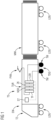
- FIG 1 shows a schematic side view of a rail vehicle TZ.
- the rail vehicle TZ is designed as an example as a multiple unit with a number of carriages, whereby only one end car EW and a middle car MW coupled to it are shown. Both cars have a car body, which is supported by bogies in the form of driving bogies TDG with traction motors TM arranged therein and running bogies LDG on rails of a track (not shown).
- the rail vehicle can also be designed as a locomotive with only one car body.
- a traction system TS of the rail vehicle TZ comprises, in addition to traction motors TM in one or more motor bogies TDG, a traction converter TUR, a control device ST that controls at least the traction converter TUR, a transformer TF and a current collector PAN.
- These components of the traction system TS are shown schematically arranged in or on the end car EW. In practice, however, particularly when the end cars are also used for passenger transport, these are usually arranged in special areas within the car body, in the underfloor area, in the roof area or even distributed over several cars of the rail vehicle TZ. This means that a respective passenger compartment can be provided in the car bodies, whereby the passenger compartments of adjacent cars can be connected to one another via car transitions as shown.
- Other components of the traction system TS for example one or more traction batteries, as well as auxiliary systems that operate the components and provide comfort for the passengers, can be provided in addition and arranged accordingly. Such components are shown in the FIG 1 but not specifically shown.
- the traction system TS can be electrically connected to an overhead line of a supply network (not shown) via the pantograph PAN, which is arranged as an example in the roof area of the car body of the end car EW.
- the overhead line is supplied with a single-phase alternating voltage of 15 kV at 16.7 Hz or 25 kV at 50 Hz, which is common in Europe.
- This alternating voltage is fed to a primary winding of the transformer TF, which transforms the network-side voltage level down to a lower voltage level according to a selected transformation of the transformer TF.
- One or more secondary windings of the transformer TF are connected to one or more
- the first power converters NSR on the mains side of the traction converter TUR are connected to the first converters NSR, which are each designed as a four-quadrant controller, for example.
- the first converters NSR convert the single-phase alternating voltage of the transformer TF into a direct voltage, which is fed to a common direct voltage intermediate circuit ZK.
- One or more load-side second converters LSR of the traction converter TUR are also connected to the direct voltage intermediate circuit ZK, which are each designed as a pulse inverter, for example.
- the second converters LSR convert the direct voltage of the direct voltage intermediate circuit ZK into a three-phase alternating voltage of variable frequency and amplitude, for example, with which stator windings of one or more traction motors TM are fed.
- the respective function of the converters NSR, LSR is controlled by the central control device ST of the traction system TS or the traction converter TUR.
- FIG 2 shows the traction system TS of the FIG 1 in a more detailed schematic representation.
- the primary winding of the transformer TF is therefore connected on the one hand to the pantograph PAN and on the other hand, for example, to rails via a wheel set.
- the three secondary windings of the transformer TF given as examples are each connected to a network-side first power converter NSR of the traction converter TUR, which convert the alternating voltage provided by the secondary winding into a direct voltage, with which they feed a common direct voltage intermediate circuit ZK.
- Two load-side second power converters LSR given as examples are fed from the direct voltage intermediate circuit ZK, which convert the direct voltage provided by the direct voltage intermediate circuit ZK into a three-phase alternating voltage of variable magnitude and frequency, with which, for example, a traction motor TM in the motor bogie TDG of the end car EW of the rail vehicle TZ is fed.
- every second LSR converter when designing the Traction motors TM as three-phase synchronous machines, every second LSR converter only feeds one traction motor TM at a time, while when the traction motors TM are designed as three-phase asynchronous machines, every second LSR converter can also feed several traction motors TM in parallel, for example a respective motor bogie.
- the respective function of the first and second NSR, LSR converters or in particular the switching positions of their respective power semiconductor switches is controlled by the central control device ST of the traction converter TUR or the traction system TS by means of control signals generated by the control device ST.
- the control device ST bases the control on information from various sensors SEN, in particular voltage and current sensors. Signal connections between the control device ST and the NSR, LSR converters and the SEN sensors are shown in the FIG 1 and 2 each shown by dashed lines.
- An intermediate circuit capacitance CZK is arranged in the DC voltage intermediate circuit ZK of the traction converter TUR.
- This intermediate circuit capacitance CZK shown as a single capacitance by way of example, can comprise one or more capacitors connected in parallel, whereby these can also be arranged distributed as a respective component of the second power converter LSR, for example.
- An intermediate circuit voltage UZK is present at the intermediate circuit capacitance CZK or between a first voltage potential UP1 and a second voltage potential UP2 of the DC voltage intermediate circuit ZK during normal operation of the traction converter TUR.
- a suction circuit arrangement SKA is also arranged, which is also connected to the control device ST in terms of signal technology, as again shown by means of a dashed line.
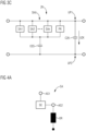
- FIG 3 shows exemplary alternative embodiments of the suction circuit arrangement SKA according to the invention, which according to the FIG 2 in the DC intermediate circuit ZK and parallel to an intermediate circuit capacitance CZK.
- the suction circuit arrangement SKA of the FIG 3A comprises a switching arrangement SA and a capacitive energy storage device CES connected in series with it.
- the switching arrangement SA is connected to the first voltage potential UP1 of the DC intermediate circuit ZK, while the capacitive energy storage device CES is connected to the second voltage potential UP2 of the DC intermediate circuit ZK.
- the arrangement of the two components SA, CES of the absorption circuit arrangement SKA and their connection to the voltage potentials UP1, UP2 of the DC intermediate circuit ZK is chosen as an example.
- the alternative suction circuit arrangement SKA of the FIG 3B comprises two parallel-connected switching arrangements SA1, SA2 and a common capacitive energy storage device CES connected in series with these.
- the other alternative suction circuit arrangement SKA of the FIG 3C comprises a plurality of parallel-connected switching arrangements SA1 to SAn and in turn a common capacitive energy storage device CES connected in series with these.
- a parallel connection of several switching arrangements SA according to the FIG 3B and 3C enables a scaling of the performance of the suction circuit arrangement SKA, whereby the switching arrangements SA or their switching units SE can be controlled by the control device ST, for example, with a time offset or a phase offset.
- a protection unit PR which is connected in parallel to the switching arrangements SA1 to SAn.
- Such a protection unit PR preferably also comprises the suction circuit arrangements SKA of the FIG 3A and 3B .
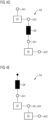
- FIG 4 shows exemplary alternative embodiments of a switching arrangement SA of the inventive suction circuit arrangement SKA.
- the alternative switching arrangements SA of the FIG 4A and 4B Each comprises a switching unit SE with a first connection AS1, a second connection AS2 and an inductance DR connected in series with the switching unit SE.
- the inductance DR can alternatively be connected to the first terminal AS1 due to the series connection, according to the FIG 4A , or the second connection AS2, according to the FIG 4B , the switching unit SE.
- each comprise two switching units SE connected in series, whereby the inductance DR is in turn alternatively connected to the second terminal AS2 of the second or, in the illustration, lower switching unit SE, according to the FIG 4C , or with the second connection AS2 of the first or upper switching unit SE and the first connection AS1 of the second or lower switching unit SE, according to the FIG 4D , or with the first connection AS1 of the first or upper switching unit SE, according to the FIG 4E , can be connected.
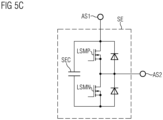
- FIG 5 shows exemplary alternative embodiments of a switching unit SE of a switching arrangement SA of the suction circuit arrangement SKA according to the invention.
- the switching unit SE of the FIG 5A comprises a half-bridge with two power semiconductor switches LSIP, LSIN, each of which is designed as an IGBT made of a silicon semiconductor material.
- the power semiconductor switches LSIP, LSIN have, in particular depending on the intermediate circuit voltage UZK and the number of switching units SE of the switching arrangement SA connected in series, a nominal blocking voltage strength of, for example, 1.2 kV, 1.7 kV, 2.3 kV, 3.3 kV, 4.5 kV or 6.5 kV.
- Switching positions of the power semiconductor switches LSIP, LSIN are controlled by the control device ST with a switching frequency that corresponds to a multiple of twice the frequency of the supply network.
- a voltage of zero volts or a voltage corresponding to the voltage at the switching unit capacitance SEC of the switching unit SE can be present at the connections AS1, AS2 of the switching unit SE.
- the first connection AS1 of the switching unit SE is connected to an outer connection of the half-bridge or the upper power semiconductor switch LSIP, while the second connection AS2 of the switching unit SE is connected to the middle connection of the half-bridge.
- Each of the power semiconductor switches LSIP, LSIN is assigned an anti-parallel connected diode DP, DN or freewheeling diode.
- the switching unit capacitance SEC connected in parallel to the half-bridge is designed, for example, as a film or electrolytic capacitor. To increase the capacity of the switching unit capacitance SEC, several such capacitors or, alternatively, additional double-layer capacitors or battery cells can be connected in parallel.
- the alternative design of the switching device SE of the FIG 5B comprises a total of four power semiconductor switches connected to form a full bridge, with at least two power semiconductor switches connected to a respective half bridge, and two half bridges and the at least one switching unit capacitance connected in parallel. Each power semiconductor switch is in turn assigned an anti-parallel connected diode or freewheeling diode.
- the first connection AS1 of the switching unit SE is connected to the center connection of the left of the two half bridges and the second terminal AS2 of the switching unit SE is connected to the center terminal of the right of the two half-bridges.
- the alternative design of the switching device SE of the FIG 5C in turn includes a half-bridge corresponding to the FIG 5A , but with the difference that the power semiconductor switches LSMP, LSMN are each designed as a MOSFET made of a silicon carbide semiconductor material.
- the antiparallel-connected diodes can be contained intrinsically in the respective MOSFET, but alternatively they can also be implemented as separate components.
- FIG 6 shows a suction circuit arrangement SKA according to the invention in a direct voltage intermediate circuit ZK.
- the switching units SEpq comprise, in accordance with the FIG 5A a respective half-bridge with two power semiconductor switches LSIPpq, LSINpq, each designed as an IGBT, and freewheeling diodes DPpq connected in anti-parallel to these. Furthermore, the switching units SEpq each comprise a switching unit capacitance SECpq connected in parallel to the half-bridge.
- the power semiconductor switches LSIPpq, LSINpq have a blocking voltage strength of, for example, 1.2 kV or 1.7 kV, and the switching unit capacitances SECpq have a dielectric strength in the range between 700 V and 1.2 kV.
- suction circuit arrangement SKA of the FIG 6 a switch TRq connected in series with a respective switching arrangement SAq.
- These switches TRq are designed, for example, as a respective circuit breaker or isolating switch, and enable the separation of a respective switching arrangement SAq from the DC intermediate circuit ZK. If a fault occurs, for example in a component of the first switching arrangement SA1, the operation of the absorption circuit arrangement SKA can thus be continued with the further switching arrangements SA2 to SAn.
- the absorption circuit arrangement SKA also comprises a protection unit PR connected in parallel to the switching arrangements SAq in order to guide a surge current occurring, for example, due to a short circuit in the DC intermediate circuit ZK or a collapse of the intermediate circuit voltage and a resulting discharge of the intermediate circuit capacitance, in particular past the freewheeling diodes DPpq, DNpq of the switching units SEpq.
- the protection unit PR comprises, for example, a series connection of a mains diode and a resistor, in particular with an ohmic resistance between 2 and 200 milliohms.
- a first voltage potential UP1 of the DC intermediate circuit ZK is assumed to be positive and a second voltage potential UP2 is assumed to be negative.
- a current IDRq through an inductance DRq is positive if it flows from the direction of the positive first voltage potential UP1 in the direction of the negative second voltage potential UP2 of the DC intermediate circuit ZK.
- a voltage UDRq at an inductance DRq is positive if it is oriented from the positive first voltage potential UP1 to the negative second voltage potential UP2
- a voltage USECpq at a switching capacitance SEpq is positive if it is oriented from the first connection AS1 to the second connection AS2 of the switching unit SEpq.
- Table A shows the FIG 6 Switching states of the four power semiconductor switches LSIPpq, LSINpq of the two switching units SEAq, SEBq of a switching arrangement SAq, controlled by a control device ST (not shown), as well as a state corresponding to a respective combination of switching states.
- Switching state 1 designates passing through, while switching state 0 designates blocking.
- Table A Condition switching state LSIPAq LSINAq LSIPBq LSINBq Z1q 1 0 1 0 Z2Aq 0 1 1 0 Z2Bq 1 0 0 1 Z3q 0 1 0 1
- Table B shows a voltage UDRq at the inductance DRq of a switching arrangement SAq resulting from the selected state as well as a corresponding effect on the voltage USECAq, USECBq at the switching unit capacitances SECAq, SECBq of the two switching units SEAq, SEBq depending on the direction of the current IDRq through the inductance DRq.
- the voltages USECAq, USECBq at the switching unit capacitances SECAq, SECBq of the two switching units SEAq, SEBq of the switching arrangement SAq are considered to be equal or only differ by a few volts or percentage points, both can be designated with USECCq.
- the selected switching frequency is used to switch back and forth between the states Z1q and Z2pq or between Z3q and Z2pq.
- the state Z2pq is obtained in accordance with the following table C.
- Table D shows which state or which switching state combination is selected to set a positive or negative voltage UDRq at the inductance DRq of the switching arrangement SAq.
- FIG 7 shows an alternative inventive absorption circuit arrangement SKA in a DC voltage intermediate circuit ZK.
- Each of the switching arrangements SAq comprises only one switching unit SEq and an inductance DRq connected in series with the respective switching unit SEq.
- the switching units SEq comprise in accordance with the FIG 5C a respective half-bridge with two power semiconductor switches LSMPq, LSMNq, each designed as a MOSFET, and freewheeling diodes DPq, DNq connected in antiparallel to these.
- the suction circuit arrangement SKA includes the FIG 7 switches TRq connected in series with a respective switching arrangement SAq. These switches TRq are designed, for example, as a respective circuit breaker or isolating switch, and enable the separation of a respective switching arrangement SAq from the DC intermediate circuit ZK. If a fault occurs, for example in a component of the first switching arrangement SA1, the operation of the absorption circuit arrangement SKA can be continued with the other switching arrangements SA2 to SAn.
- the absorption circuit arrangement SKA also comprises a protection unit PR connected in parallel to the switching arrangements SAq in order to guide a surge current occurring, for example, due to a short circuit in the DC intermediate circuit ZK, past the freewheeling diodes DPq of the switching units SEq.
- the protection unit PR comprises, for example, a series connection of a mains diode and a resistor, in particular with an ohmic resistance between 2 and 200 milliohms.
- the following table E shows the switching states of the two power semiconductor switches LSMPq, LSMNq of the switching unit SEq of the switching arrangement SAq, controlled by the control device ST, as well as a Combination of switching states corresponding state.
- Switching state 1 means passing through, while switching state 0 means blocking.
- Table E Condition switching state LSMPq LSMNq Z1q 1 0 Z3q 0 1
- Table G shows which state or which switching state combination is selected to set a positive or negative voltage UDRq at the inductance DRq of the switching arrangement SAq.
- an absorption circuit arrangement can in particular comprise only a single switching arrangement SA with one or more switching units SE connected in series. Protection of the diodes of a switching unit against surge currents can also be achieved in a manner other than by a described protective unit PR, for example by a unit connected in series with a switching unit which, when a predetermined threshold value for the current is exceeded or the current is integrated over a predetermined period of time, interrupts the current flow through the switching unit and/or directs the current flow past the switching units or certain components of these switching units via one or more current paths of lower impedance.
Landscapes
- Engineering & Computer Science (AREA)
- Power Engineering (AREA)
- Transportation (AREA)
- Mechanical Engineering (AREA)
- Life Sciences & Earth Sciences (AREA)
- Sustainable Development (AREA)
- Sustainable Energy (AREA)
- Inverter Devices (AREA)
- Dc-Dc Converters (AREA)
Applications Claiming Priority (1)
| Application Number | Priority Date | Filing Date | Title |
|---|---|---|---|
| DE102023206584.3A DE102023206584A1 (de) | 2023-07-11 | 2023-07-11 | Saugkreisanordnung für einen Traktionsumrichter eines Schienenfahrzeugs |
Publications (1)
| Publication Number | Publication Date |
|---|---|
| EP4492663A1 true EP4492663A1 (fr) | 2025-01-15 |
Family
ID=91469937
Family Applications (1)
| Application Number | Title | Priority Date | Filing Date |
|---|---|---|---|
| EP24181114.0A Pending EP4492663A1 (fr) | 2023-07-11 | 2024-06-10 | Circuit d'aspiration pour un convertisseur de traction d'un véhicule ferroviaire |
Country Status (4)
| Country | Link |
|---|---|
| US (1) | US12466269B2 (fr) |
| EP (1) | EP4492663A1 (fr) |
| CN (1) | CN119315797A (fr) |
| DE (1) | DE102023206584A1 (fr) |
Citations (8)
| Publication number | Priority date | Publication date | Assignee | Title |
|---|---|---|---|---|
| CN1816462A (zh) * | 2003-07-04 | 2006-08-09 | 西门子公司 | 牵引整流器的过电压限幅器 |
| JP2009261242A (ja) * | 2004-06-22 | 2009-11-05 | Toshiba Corp | 電気車の制御装置 |
| US20090322148A1 (en) * | 2006-08-09 | 2009-12-31 | Mitsubishi Electric Corporation | Power converter and controller using such power converter for electric rolling stock |
| DE102009017254A1 (de) * | 2009-04-09 | 2010-10-21 | Siemens Aktiengesellschaft | Vorrichtung zur Ankopplung von Energiespeichern an einem Spannungszwischenkreis eines Traktionsstromrichters |
| US20150055387A1 (en) * | 2012-05-10 | 2015-02-26 | Tomas Tengner | Battery Energy Storage and Power System |
| EP2595291B1 (fr) * | 2011-11-15 | 2020-04-08 | Schneider Toshiba Inverter Europe SAS | Convertisseur de puissance doté de plusieurs sources de courant commandées connectées en parallèle |
| CN116031859A (zh) * | 2023-01-03 | 2023-04-28 | 中海石油(中国)有限公司 | 一种多逆变器共直流母线谐振抑制方法及系统 |
| CN116054542A (zh) * | 2022-11-29 | 2023-05-02 | 华中科技大学 | 一种低开关频率的模块化直流有源滤波装置及控制方法 |
Family Cites Families (7)
| Publication number | Priority date | Publication date | Assignee | Title |
|---|---|---|---|---|
| DE19712564C1 (de) * | 1997-03-25 | 1998-06-25 | Siemens Ag | Schaltungsanordnung |
| DE102006043941A1 (de) * | 2006-09-14 | 2008-04-03 | Bombardier Transportation Gmbh | Antriebsenergieversorgung bei Schienenfahrzeugen |
| DE102007006840B3 (de) | 2007-02-12 | 2008-04-24 | Siemens Ag | Dämpfungselement |
| JP6564470B2 (ja) * | 2015-12-09 | 2019-08-21 | 川崎重工業株式会社 | 鉄道車両用制御装置、列車編成および主電動機制御方法 |
| JP7168375B2 (ja) * | 2018-08-10 | 2022-11-09 | 東海旅客鉄道株式会社 | 集電電流監視装置 |
| MX2023008827A (es) * | 2022-03-01 | 2023-09-14 | Canadian Pacific Railway Company | Aparato y metodo de locomotora accionada electricamente. |
| DE102022107475A1 (de) | 2022-03-30 | 2023-10-05 | Audi Aktiengesellschaft | Elektrische Schaltungsanordnung, Kraftfahrzeug und Verfahren zum Betrieb einer elektrischen Schaltungsanordnung |
-
2023
- 2023-07-11 DE DE102023206584.3A patent/DE102023206584A1/de active Pending
-
2024
- 2024-06-10 EP EP24181114.0A patent/EP4492663A1/fr active Pending
- 2024-07-09 CN CN202410912420.0A patent/CN119315797A/zh active Pending
- 2024-07-11 US US18/769,632 patent/US12466269B2/en active Active
Patent Citations (8)
| Publication number | Priority date | Publication date | Assignee | Title |
|---|---|---|---|---|
| CN1816462A (zh) * | 2003-07-04 | 2006-08-09 | 西门子公司 | 牵引整流器的过电压限幅器 |
| JP2009261242A (ja) * | 2004-06-22 | 2009-11-05 | Toshiba Corp | 電気車の制御装置 |
| US20090322148A1 (en) * | 2006-08-09 | 2009-12-31 | Mitsubishi Electric Corporation | Power converter and controller using such power converter for electric rolling stock |
| DE102009017254A1 (de) * | 2009-04-09 | 2010-10-21 | Siemens Aktiengesellschaft | Vorrichtung zur Ankopplung von Energiespeichern an einem Spannungszwischenkreis eines Traktionsstromrichters |
| EP2595291B1 (fr) * | 2011-11-15 | 2020-04-08 | Schneider Toshiba Inverter Europe SAS | Convertisseur de puissance doté de plusieurs sources de courant commandées connectées en parallèle |
| US20150055387A1 (en) * | 2012-05-10 | 2015-02-26 | Tomas Tengner | Battery Energy Storage and Power System |
| CN116054542A (zh) * | 2022-11-29 | 2023-05-02 | 华中科技大学 | 一种低开关频率的模块化直流有源滤波装置及控制方法 |
| CN116031859A (zh) * | 2023-01-03 | 2023-04-28 | 中海石油(中国)有限公司 | 一种多逆变器共直流母线谐振抑制方法及系统 |
Non-Patent Citations (3)
| Title |
|---|
| COSMIN GALEA ET AL: "New topology of electronic smoothing inductor used in three phase electric drives", ELECTRICAL POWER QUALITY AND UTILISATION (EPQU), 2011 11TH INTERNATIONAL CONFERENCE ON, IEEE, 17 October 2011 (2011-10-17), pages 1 - 6, XP032092229, ISBN: 978-1-4673-0379-8, DOI: 10.1109/EPQU.2011.6128837 * |
| GAUTAM ADITYA R ET AL: "Control Strategies and Power Decoupling Topologies to Mitigate 2[omega]-Ripple in Single-Phase Inverters: A Review and Open Challenges", IEEE ACCESS, IEEE, USA, vol. 8, 7 August 2020 (2020-08-07), pages 147533 - 147559, XP011805980, DOI: 10.1109/ACCESS.2020.3015315 * |
| KLEIN-HESSLING ANNEGRET ET AL: "Active DC-Power Filters for Switched Reluctance Drives based on Dual- Active Bridge Converters", 2019 IEEE INTERNATIONAL ELECTRIC MACHINES & DRIVES CONFERENCE (IEMDC), IEEE, 12 May 2019 (2019-05-12), pages 1694 - 1699, XP033588553, DOI: 10.1109/IEMDC.2019.8785170 * |
Also Published As
| Publication number | Publication date |
|---|---|
| CN119315797A (zh) | 2025-01-14 |
| US20250018803A1 (en) | 2025-01-16 |
| DE102023206584A1 (de) | 2025-01-16 |
| US12466269B2 (en) | 2025-11-11 |
Similar Documents
| Publication | Publication Date | Title |
|---|---|---|
| EP0832006B1 (fr) | Systeme convertisseur haute tension | |
| EP2611643B1 (fr) | Système d'alimentation en énergie électrique destiné à des dispositifs d'entraînement de véhicules ferroviaires | |
| EP0820893B1 (fr) | Système de traction pour véhicule sur rails et procédé de commande correspondant | |
| EP0384222B1 (fr) | Circuit d'alimentation pour une locomotive à systèmes multiples | |
| EP2609676B1 (fr) | Convertisseur de traction | |
| DE3817652C2 (fr) | ||
| EP2067227B1 (fr) | Alimentation en énergie motrice pour véhicules ferroviaires | |
| DE102018001032A1 (de) | Motorantriebsvorrichtung | |
| EP3290254A1 (fr) | Convertisseur de reseau de bord bidirectionnel et son procede de fonctionnement | |
| EP2728735A2 (fr) | Convertisseur de traction modulaire avec accumulateur d'énergie pour fournir une tension de circuit intermédiaire et procédé d'operation | |
| DE69625456T2 (de) | Steuereinrichtung für ein Elekrofahrzeug | |
| EP1350666B1 (fr) | Ensemble circuit et méthode pour alimentation et récupération électrique d'une ligne de contact | |
| EP2416980B1 (fr) | Dispositif permettant de coupler des accumulateurs d'energie au circuit de tension intermédiaire d'un convertisseur de courant de traction | |
| EP0670236A1 (fr) | Alimentation pour voitures passagers de trains | |
| EP0952030B1 (fr) | Circuit électrique d'alimentation pour un système d'entraînement électrique | |
| DE102021213545B3 (de) | Vorrichtung zum gesteuerten Herstellen eines Kurzschlusses in einem Antriebssystem eines Schienenfahrzeugs | |
| EP0637121B1 (fr) | Ensemble de convertisseur pour l'alimentation d'un circuit intermédiaire en courant continu | |
| EP0743744A2 (fr) | Convertisseur de courant | |
| EP4662775A1 (fr) | Système d'entraînement électrique et son procédé de fonctionnement | |
| EP4492663A1 (fr) | Circuit d'aspiration pour un convertisseur de traction d'un véhicule ferroviaire | |
| WO2000051839A1 (fr) | Circuit d'injection sans transformateur pour wagons de chemin de fer | |
| EP0300392A2 (fr) | Circuit de redressement pour alimenter un circuit de circulation intermédiaire en courant continu | |
| DE10214509A1 (de) | Stromrichteranordnung zur Speisung einer dreiphasigen Last aus einem einphasigen Netz | |
| DE3907940A1 (de) | Verfahren zur symmetrierung der spannungsaufteilung an stromrichtern mit mehrpunktschaltung | |
| EP2642652A1 (fr) | Convertisseur de source de tension avec circuit intermédiaire de capacité faible (F3E) et avec condensateur additif controlé et procédé de fonctionnement |
Legal Events
| Date | Code | Title | Description |
|---|---|---|---|
| PUAI | Public reference made under article 153(3) epc to a published international application that has entered the european phase |
Free format text: ORIGINAL CODE: 0009012 |
|
| STAA | Information on the status of an ep patent application or granted ep patent |
Free format text: STATUS: THE APPLICATION HAS BEEN PUBLISHED |
|
| AK | Designated contracting states |
Kind code of ref document: A1 Designated state(s): AL AT BE BG CH CY CZ DE DK EE ES FI FR GB GR HR HU IE IS IT LI LT LU LV MC ME MK MT NL NO PL PT RO RS SE SI SK SM TR |
|
| STAA | Information on the status of an ep patent application or granted ep patent |
Free format text: STATUS: REQUEST FOR EXAMINATION WAS MADE |
|
| 17P | Request for examination filed |
Effective date: 20250304 |
|
| RAP3 | Party data changed (applicant data changed or rights of an application transferred) |
Owner name: SIEMENS MOBILITY GMBH |