EP4492673A1 - Dispositif de commande de moteur et procédé de réglage automatique de celui-ci - Google Patents
Dispositif de commande de moteur et procédé de réglage automatique de celui-ci Download PDFInfo
- Publication number
- EP4492673A1 EP4492673A1 EP23766303.4A EP23766303A EP4492673A1 EP 4492673 A1 EP4492673 A1 EP 4492673A1 EP 23766303 A EP23766303 A EP 23766303A EP 4492673 A1 EP4492673 A1 EP 4492673A1
- Authority
- EP
- European Patent Office
- Prior art keywords
- identification
- difference signal
- command
- motor
- interval
- Prior art date
- Legal status (The legal status is an assumption and is not a legal conclusion. Google has not performed a legal analysis and makes no representation as to the accuracy of the status listed.)
- Pending
Links
Images


Classifications
-
- G—PHYSICS
- G05—CONTROLLING; REGULATING
- G05B—CONTROL OR REGULATING SYSTEMS IN GENERAL; FUNCTIONAL ELEMENTS OF SUCH SYSTEMS; MONITORING OR TESTING ARRANGEMENTS FOR SUCH SYSTEMS OR ELEMENTS
- G05B11/00—Automatic controllers
- G05B11/01—Automatic controllers electric
- G05B11/36—Automatic controllers electric with provision for obtaining particular characteristics, e.g. proportional, integral, differential
-
- H—ELECTRICITY
- H02—GENERATION; CONVERSION OR DISTRIBUTION OF ELECTRIC POWER
- H02P—CONTROL OR REGULATION OF ELECTRIC MOTORS, ELECTRIC GENERATORS OR DYNAMO-ELECTRIC CONVERTERS; CONTROLLING TRANSFORMERS, REACTORS OR CHOKE COILS
- H02P21/00—Arrangements or methods for the control of electric machines by vector control, e.g. by control of field orientation
- H02P21/14—Estimation or adaptation of machine parameters, e.g. flux, current or voltage
- H02P21/143—Inertia or moment of inertia estimation
-
- H—ELECTRICITY
- H02—GENERATION; CONVERSION OR DISTRIBUTION OF ELECTRIC POWER
- H02P—CONTROL OR REGULATION OF ELECTRIC MOTORS, ELECTRIC GENERATORS OR DYNAMO-ELECTRIC CONVERTERS; CONTROLLING TRANSFORMERS, REACTORS OR CHOKE COILS
- H02P21/00—Arrangements or methods for the control of electric machines by vector control, e.g. by control of field orientation
- H02P21/14—Estimation or adaptation of machine parameters, e.g. flux, current or voltage
- H02P21/16—Estimation of constants, e.g. the rotor time constant
-
- H—ELECTRICITY
- H02—GENERATION; CONVERSION OR DISTRIBUTION OF ELECTRIC POWER
- H02P—CONTROL OR REGULATION OF ELECTRIC MOTORS, ELECTRIC GENERATORS OR DYNAMO-ELECTRIC CONVERTERS; CONTROLLING TRANSFORMERS, REACTORS OR CHOKE COILS
- H02P21/00—Arrangements or methods for the control of electric machines by vector control, e.g. by control of field orientation
- H02P21/14—Estimation or adaptation of machine parameters, e.g. flux, current or voltage
- H02P21/18—Estimation of position or speed
-
- H—ELECTRICITY
- H02—GENERATION; CONVERSION OR DISTRIBUTION OF ELECTRIC POWER
- H02P—CONTROL OR REGULATION OF ELECTRIC MOTORS, ELECTRIC GENERATORS OR DYNAMO-ELECTRIC CONVERTERS; CONTROLLING TRANSFORMERS, REACTORS OR CHOKE COILS
- H02P21/00—Arrangements or methods for the control of electric machines by vector control, e.g. by control of field orientation
- H02P21/22—Current control, e.g. using a current control loop
Definitions
- This invention relates to a control device for a motor and its automatic adjustment method.
- a method of automatically adjusting a motor control device based on the characteristics of an industrial machine after automatically ascertaining them has been proposed in the past.
- the characteristics of an industrial machine in this case are, for example, the moment of inertia of the motor shaft,viscous friction, coulomb friction, static friction, resonance characteristics, and other physical characteristics related to the control performance of the industrial machine in which the motor is installed.
- patent document 1 provides a method for on-line estimation of the moment of inertia and viscous friction coefficient, taking coulomb friction into account, even when the motor rotation angular velocity is low.
- coulomb friction is regarded as a constant value disturbance, and differential processing is applied to the observed values of motor torque and rotation angular velocity to remove the effect of the constant value disturbance before estimating the moment of inertia and viscous friction coefficient.
- Patent Document 1 Japanese patent publication No. 2006-217729
- the patent document 1 uses differential processing, but differential processing emphasizes high-frequency noise superimposed on the observed values of motor torque and motor rotation angular velocity, and even if a low-pass filter is applied to remove the high-frequency noise, it is not necessarily advantageous for the purpose of highly accurate estimation of the moment of inertia and viscous friction coefficient (hereinafter referred to as the mechanical system parameters). In particular, this process is not desirable, especially when the motor rotation angular velocity is low and noise has a strong influence.
- the purpose of this invention is to estimate the moment of inertia and viscous friction with high accuracy even when the rigidity of the machine is low.
- a preferred example of the invention is a motor control device that controls a machine comprising an identification part estimating a moment of inertia and viscous friction, a speed command generation part generating a speed command obtained by integrating an acceleration command, a difference signal calculation part calculating a difference signal from the acceleration command with time difference, and an identification interval judgment part determining a valid interval for operate the identification part based on the difference signal, and operating the identification part in the valid interval, and driving the motor based on the speed command generated by the speed command generating part, wherein the identification part estimates the moment of inertia and the viscous friction.
- the moment of inertia and viscous friction can be accurately estimated even when the rigidity of the machine is low.
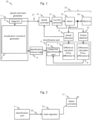
- Fig 1 shows the first basic configuration of Example 1.
- the motor control device 19 in this example has a configuration other than the machine 15 assembled with the motor, which consists of the motor 13 and the machine 14 in Fig. 1 .
- the motor control device 19 has a current controller 12 and a speed controller 11 that control the motor 13 assembled with the machine 14, a speed command generator 1 that provides the speed command to the speed controller 11, identification part 5 that estimates the moment of inertia and viscous friction coefficient, which are mechanical characteristics of the machine 15 assembled with the motor 13, based on the observed values of the motor torque and the motor rotation angular velocity provided by the torque detector 10 and the speed detector 9, respectively, and identification interval judge 4 that operates the identification part 5 based on the acceleration command provided by the acceleration command generator 2 included in the speed command generator 1.
- the motor control device 19 speed detector 9 and torque detector 10 are composed of hardware.
- Speed command generator 1, identification interval judge 4, identification part 5, speed controller 11 and current controller 12 are composed of software in which a processor reads a program stored in a memory or other storage device and executes each function.
- the speed command generator 1 consists of the acceleration command generator 2 and the integrator 3.
- the speed command generator 1 generates the speed command 17 by the integrator 3 performing an integration process on the acceleration command generated by the acceleration command generator 2.
- the speed detector 9 detects the angular speed of rotation of the motor shaft of motor 13 and outputs it as an observed value of the angular speed of motor rotation, and based on the speed command 17 and the observed value of the angular speed of motor rotation, the speed controller 11 calculates the command value of the motor torque (motor torque command) is calculated.
- the speed detector 9 calculates the observed value of the motor rotation angular speed from the rotational position of the motor shaft provided by the encoder attached to the motor 13, for example.
- the current controller 12 provides voltage commands to the motor 13 so that the motor torque delivered by the motor 13 to the machine 14 follows the motor torque command.
- the torque detector 10 detects the motor torque supplied by the motor 13 and calculates the observed value of the motor torque.
- the torque detector 10 for example, detects the current of the motor 13 with a current sensor and calculates the motor torque by multiplying it by a torque multiplier.
- the identification part 5 consists of a sequential identification part 6, a difference calculator 7, and a difference calculator 8.
- the sequential identification part 6 estimates the moment of inertia and viscous friction coefficient cyclically and sequentially based on the outputs of difference calculator 7 and difference calculator 8.
- the timing for performing the identification depends on the instructions from the identification interval judge 4.
- the identification part 5 identifies a model of the mechanical characteristics of the machine 15 in which the motor 13 is assembled, and estimates the mechanical system parameters based on the identified model.
- an auto-regulator may be included that the motor control device 19 automatically adjusts the control gain of the speed controller and/or position controller based on the moment of inertia and viscous friction coefficient estimated by the sequential identification part 6.
- Fig. 2 shows the configuration of a variant of Example 1 that includes an auto-regulator. Based on the moment of inertia and viscous friction coefficient information 22 calculated by the identification part 5, the auto-regulator 21 calculates an appropriate control gain of the speed controller 11 for the machine 15 on which the motor 13 is assembled, and sets the control gain in the speed controller 11.
- speed controller 11 is, for example, a PI (Proportional-Integral) controller and the desired responsiveness is set by the user.
- PI Proportional-Integral
- auto-regulator 21 calculates the P-gain and I-gain that achieve the desired responsiveness based on the moment of inertia and viscous friction coefficient, and sets the result to speed controller 11. This makes it possible to provide a motor control device 19 that can automatically adjust the speed controller 11.
- the sequential identification part 6 consists of a mechanical system parameter sequential identification calculator 33, low-pass filters (hereinafter referred to as LPF) 35 to 37, and an acceleration calculator 34.
- LPF low-pass filters
- the speed detector 9 and torque detector 10 each include a down sampler 31 and a down sampler 32.
- the speed detector 9 calculates the observed value of the motor rotational angular velocity for identification via the down sampler 31.
- the torque detector 10 calculates the observed value of the motor torque for identification via the down sampler 32.
- TID TID > TSP is acceptable, given the background that high speed control response is desired in recent years. Therefore, down-sampler 31 and down-sampler 32 are responsible for adjusting and resampling the period of the signal so that the observed values of the motor rotation angular velocity and the motor torque are in the period of the identification period TID, respectively.
- TID may be TID > 10 ⁇ TSP, and the identification period TID shall be set sufficiently long compared to TSP.
- the down-sampler 31 and down-sampler 32 may employ, for example, a decimation filter.
- coulomb friction When the machine 14 is operating at nonzero speed, coulomb friction generally affects the observed values of motor torque and the observed values of motor rotational angular velocity as a constant value torque disturbance.
- Coulomb friction is one of the dynamic frictions and refers to a constant value frictional force that acts to prevent the machine from moving out of the static friction region and independent of the speed at which the machine is moving during operation.
- the identification part 5 employs a difference calculator 7 and a difference calculator 8 to eliminate this effect. This is because the difference in motor torque, etc., in the difference calculator, which considers time differences, eliminates the effect of coulomb friction, which is a constant value friction force.
- Fig. 4 illustrates the linear difference filter.
- Fig. 5 shows the frequency responses of the linear difference filter and the differentiator.
- the difference calculator 7 and difference calculator 8 are the linear difference filters shown in Fig. 4 and the following formula (1).
- y t A x t ⁇ x t ⁇ n ⁇ T ID
- the Z -n in Fig. 4 is the delay operator in the discrete system.
- the linear-difference filter has an advantage over differential processing in that it can remove the effects of coulomb friction without causing a significant decrease in SN ratio.
- the linear difference filter has the disadvantage that it must always keep past values of the input signal x by the time difference ⁇ .
- the memory capacity for storing past signals increases as the positive integer n for the time difference ⁇ increases, and arithmetic resources are required for memory management.
- linear-difference filter Another disadvantage of the linear-difference filter is that it has a significant response delay. Since the influence of the initial state of the linear difference filter remains on the output of the linear difference filter from the time difference ⁇ after receiving the first input until the time difference ⁇ elapses, an accurate difference signal for the input signal is output after the time difference ⁇ . Therefore, it is desirable for identification part 5 to perform identification using the accurate difference signal.
- identification interval judge 4 does not operate sequential identification part 6 in the identification part 5 as long as the effect of the initial state of the linear difference filter remains, as described in detail below.
- Sequential identification part 6 in Fig. 3 operates in the identification cycle TID. It operates only during the time interval indicated by the identification interval judge 4.
- the output of difference calculator 7 is s(t) and the output of difference calculator 8 is T(t).
- sequential identification part 6 receives s(t) and T(t)
- acceleration calculator 34 differentiates s(t) to output a(t).
- the differentiation process in the digital arithmetic unit is realized by incomplete differentiation, etc.
- s(t), a(t), and T(t) are processed by LPF35, LPF36, and LPF37, respectively, and the results are input to the mechanical system parameter sequential identification calculator 33.
- the mechanical system parameter sequential identification calculator 33 is specifically calculated by sequential processing (identification cycle TID) according to the following formulas (2) to (6).
- identification cycle TID sequential processing
- the signals after being processed by LPF 35 to 37 are denoted as s(t), a(t), and T(t), respectively.
- J(k) and D(k) are the kth step estimates of the moment of inertia and viscous friction coefficient, and ⁇ (k) is the vector of these estimates.
- kth step refers to the kth calculation step performed by the mechanical system parameter sequential identification calculator 33.
- P(0) is the initial value of the sequential identification
- ⁇ is a forgetting coefficient set at 0 ⁇ ⁇ ⁇ 1.
- the ⁇ is a parameter that determines the degree to which the effect of past signals is reflected in the identification at the current time, and the closer it is to 1, the more the effect of past signals is reflected.
- LPFs 35-37 are provided to remove noise superimposed on s(t), a(t) and T(t).
- a LPF with a first-order delay system may be employed, as shown in the following formula (7).
- [number 7] LPF s ⁇ s + ⁇ where, s and ⁇ are the Laplace operator and the cutoff frequency [rad/s] of the LPF, respectively.
- LPFs 35 to 37 should be the same so that the phase of each signal used for identification is aligned.
- formula (7) is expressed as a continuous-time system, but it is discretized and implemented in a digital arithmetic unit.
- the vibration of the machine caused by low rigidity is generally several Hz to several tens of Hz, and therefore the torque disturbance caused by this vibration is also several Hz to several tens of Hz.
- the cutoff characteristics of LPF 35-37 be set low enough to remove torque disturbances caused by mechanical vibration.
- this example is equipped with a speed command generator 1.
- the speed command generator 1 generates a smooth speed command that does not excite vibrations in the machine based on the acceleration command generator 2.
- the acceleration command generator 2 in this example has the ability to design the acceleration command so that the maximum and minimum values of the acceleration command and the zero point are connected by a combination of functions of first order (linear) or higher, and the speed command obtained by integrating them is the function allows the design of the acceleration command to produce a smooth one that does not contain the dominant frequency component that excites the machine.
- the acceleration command generator 2 holds pre-designed acceleration commands and generates and outputs acceleration commands based on the pre-designed acceleration commands.
- the command may be designed arbitrarily by the user, or a pre-designed one may be selected for use.
- Fig. 6 shows a specific example of the relationship between the acceleration command (vertical axis) and time (horizontal axis) in the acceleration command generator 2 in this example.
- the upper part of Fig. 6 shows the zero point 61 and zero point 64, maximum point 62, and minimum point 63 of the acceleration command.
- the lower part of Fig. 6 shows the case where the zero points 61 and 64, the maximum point 62, and the minimum point 63 (but in this example, they are each a group of points) are connected by a linear function.
- the zero point 61 and the maximum point 62 are connected by a linear function 65 and a linear function 66 with different slopes and lengths, as are the zero point 64 and the minimum point 63.
- the maximum point 62 and minimum point 63 are connected by a linear function 67.
- the zero point 61 and zero point 64, maximum point 62, and minimum point 63 are also cases where the points in the point group are connected by a linear function.
- the zero point 61 and the maximum point 62 are composed of two linear functions with different slopes and lengths for smoothness and to shorten the travel distance (number of motor revolutions [rad]).
- the speed command is the integral of the acceleration command, and the position command is the integral of the speed command. Therefore, if the acceleration command is smooth, the speed command is also smooth, and the smaller the area of the acceleration command, the shorter the travel distance.
- coulomb friction is assumed to be a constant value torque disturbance, i.e., a constant value torque disturbance with no position dependence. Since this assumption is considered to have a higher probability of being true the shorter the travel distance, shorter travel distances are desirable from the perspective of coulomb friction elimination. In addition, considering the limited operating range of the machine, it is desirable to be able to identify even a short travel distance from the viewpoint of physical usability.
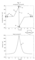
- Fig. 7 is a numerical example of the design of the acceleration command in Fig. 6 .
- the acceleration command 70 is designed as in Fig. 6
- speed command 71 is obtained by integrating acceleration command 70.
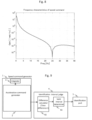
- Fig. 8 shows the frequency characteristics (gain) of speed command 71 in Fig. 7 . From Fig. 8 , it can be seen that the speed command is a smooth speed command that does not have sufficient gain in the frequency band above about 2 [Hz] and does not contain dominant frequency components that excite the machine.
- Fig. 9 illustrates identification interval judge 4.
- the identification interval judge 4 consists of difference calculator 92 and valid interval determiner 93 as shown in Fig. 9 .
- the identification part 5 is operated by determining the valid interval for identification based on the difference signal of the acceleration command calculated by the difference calculator 92.
- the sequential identification part has a forgetting factor ⁇ and should be identified only after the initial state of the difference calculators 7 and 8 is no longer affected.
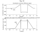
- time difference ⁇ of the difference calculator 92 is set to the same value as the difference calculator 7 and 8 that process the signals used by the identification part 5, in order to perform significant identification, one of the conditions under which the valid interval determiner 93 operates the identification part 5 is integral the difference signal output by the difference calculator 92 is that the time difference ⁇ elapses from the initial time. This is condition (A) .
- the interval from 1 to 4 seconds is the interval where condition (A) is satisfied.
- the signal used for identification should have a high signal gain from the viewpoint of SN ratio, and a higher gain of the difference signal is also expected to improve the identification accuracy in the mechanical system parameter sequential identification calculator based on the difference signal.
- one of the conditions under which the valid interval determiner 93 operates the identification part 5 is the absolute value of the difference signal obtained by processing the acceleration command with the difference calculator 92 must be greater than or equal to the predetermined value AX, or the average value of the difference signal must be greater than or equal to the predetermined value AAX in the interval. This is condition (B).
- the interval in which the difference signal of the acceleration command is zero is the interval in which the acceleration command is constant, but in this case, the mechanical characteristics related to acceleration are removed by the difference process.
- condition (C) one of the conditions under which the valid interval determiner 93 operates the identification part 5 is that the interval where the difference signal of the acceleration command is non-zero. This is condition (C).
- the valid interval judge 93 operates the identification part 5 in the interval satisfying the conditions (A) to (C) based on the acceleration command generated by the acceleration command generator 2.
- the valid interval judge 93 determines that the interval of approximately 1.6 to 3.65 seconds is a valid interval for identification and operates the identification part 5.
- the identification part 5 performs identification in this interval and completes the estimation of the mechanical parameters.
- the auto-regulator 21 shown in Fig. 2 may use a single estimation result, or the average of multiple estimation results, as the final mechanical system parameters estimation result used to adjust the controller.
- the motor control device in this example even for a machine with low rigidity, it does not excite vibration of the machine, and the SN ratio of the signal used for identification is good, and identification can be achieved at a significant interval for identification.
- the time difference ⁇ of the difference calculator 92 when the time difference ⁇ of the difference calculator 92 is set to be long, the time including the interval in which the speed of the difference signal is zero in principle tends to increase, so the speed command and the time difference ⁇ , in other words, acceleration, which is the source of the speed command, it is necessary to operate the identification part 5 with an awareness of the relationship between the command and the time difference ⁇ .
- one of the conditions for the valid interval judge 93 to operate the identification part 5 is that the difference signal output by the difference calculator 92 must be from an interval that does not include the timing when the speed command is zero.
- the effective interval determiner 93 may be configured to refer to the speed command.
- sequential identification part 6 employs a mechanical system parameter sequential identification calculator 33 with s(t), a(t), and T(t) as inputs
- an identification part with s(t) and T(t) as inputs may also be employed.
- identification part 5 uses a sequential type, a batch type identification part that operates non-sequentially may also be used.
- Fig. 11 shows Example 2.
- this example is an example of a motor control device 1100 when the configuration of the command generation and control system is different in Example 1.
- the configuration has a position command generator 1103, a position controller 1101, and a first integrator 1102 added.
- the position command generator 1103 consists of an acceleration command generator 2, a second integrator 3, and a third integrator 1104.
- the components given the same numbers as in Fig. 1 are assumed to have the same functions in Fig. 11 .
- the position command generator 1103 generates a position command.
- the position controller 1101 generates a speed command based on the position command and the observed motor rotation position obtained by integrating the observed value of the motor rotation angular velocity, so that the observed value of the motor rotation angular velocity follows the position command.
- Example 1 Even with this position control system, the machine operates based on the position command generated based on the speed command, which does not excite vibration of the machine designed based on the desired acceleration command. Therefore, the same level of estimation accuracy as in Example 1 is expected in this example.
- auto-regulator 21 shown in Fig. 2 may be used to adjust the gain of the position controller as well as the speed controller.
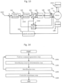
- This example is for the speed control system of AC servo motors in the cascade configuration shown in Fig. 13 .
- An example for automatically adjusting the speed control system of an AC servo motor will be described.
- a permanent magnet synchronous motor 137 operating on 3-phase AC assembled in a low rigidity machine 1313 detects the rotational position of the motor with an encoder 139, calculates an observed value of the angular speed of motor rotation with a speed calculator 1311, and based on the speed command 1314 and the observed value of the angular speed of motor rotation, speed controller 132 calculates the current command.
- the motor current of the permanent magnet synchronous motor 137 is detected by the current sensor 138 and converted into observed dq-axis current by the first coordinate converter (3-phase to dq-axis coordinate converter) 1310, the current controller 133 calculate dq-axis voltage command based on the current command and the observed dq-axis current.
- the dq-axis voltage command is converted to a 3-phase voltage command by the second coordinate converter (dq-axis to 3-phase coordinate converter) 134, which is then converted to a voltage pulse command by the PWM (Pulse Width Modulation) device 135.
- PWM Pulse Width Modulation
- the inverter 136 supplies 3-phase voltage to the permanent magnet synchronous motor 137 based on the voltage pulse commands.
- the speed controller 132, current controller 133, first coordinate converter 1310, second coordinate converter 134, PWM device 135 and speed calculator 1311 may be configured as software, and stored in a memory or other storage device and read by the processor and executed for implementing each function.
- Fig. 12 shows the processing steps of the automatic adjustment process in Example 3.
- the steps of the automatic adjustment process in this example roughly consist of the speed command generation step 1201, the identification interval determination step 1202, the identification step 1203, and the controller adjustment step 1204, as shown in Fig. 12 .
- the speed command generation step 1201 includes an acceleration command generation step, in the acceleration command generation step generating acceleration command which is the maximum and minimum values of the command and the zero point are connected by a combination of functions of the first order (linear) or more. It is the speed command generation step 1201 to generate an acceleration command so that the speed command obtained by integrating the command is smooth and does not contain a dominant frequency component that excites the machine.
- acceleration commands designed and generated in the acceleration command generation step is shown in Fig. 6 and Fig. 7 .
- the identification interval for estimating the mechanical system parameters is determined based on the acceleration command generated in the acceleration command generation step.
- the determination of whether the interval is significant for identification implementation is based on the fulfillment of conditions (A) through (C) shown in Example 1.
- Condition (D) shown in Example 1 may also be considered.
- the permanent magnet synchronous motor 137 and the low rigidity machine 1313 that are to be controlled are driven based on the speed command generated in the speed command generation step 1201.
- identification is performed in the interval judged to be significant for identification in the identification interval determination step 1202 and carry out estimation of mechanical parameters.
- identification is performed using the sequential identification method after preprocessing the observed values of motor torque and motor rotation angular velocity using a linear difference filter with a time difference of ⁇ .
- Formulas (2) to (6) can be used as the sequential identification method when acceleration is calculated explicitly.
- the linear difference filter can be found in formula (1).
- the speed command generation step 1201 to identification step 1203 may be repeated a predetermined number of times.
- the controller adjustment step 1204 performs an automatic adjustment of the control gain of the speed controller 132 to achieve the user desired responsiveness, based on the (multiple) estimates of the mechanical system parameters obtained in the identification step 1203.
- Fig. 14 shows the processing steps of the automatic adjustment process when the motor control device constitutes the position control system. Even when the motor control device constitutes the position control system, it is possible to automatically adjust the motor control device that constitutes the position control system by generating position commands in the position command generation step 1401, as shown in Fig. 14 .
- the position command generation step 1401 generates a position command by integrating the speed command generated in the speed command generation step 1201.
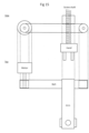
- the low rigidity machine 1313 is, for example, a take-out machine that takes out machine parts from a machine tool, as shown in Fig. 15 .
- the upper part of Fig. 15 shows a side view of the ejector machine, and the lower part of Fig. 15 shows a top view of the ejector machine.
- the automatic adjustment of the motor control device in this example is effective for machines whose mechanical properties do not change significantly as the machine moves.
- the controller adjustment step 1204 may be equipped with an auto-regulator that automatically adjusts the control gain of the controller appropriately based on the estimation results of the segmental mechanical system parameters.
Landscapes
- Engineering & Computer Science (AREA)
- Power Engineering (AREA)
- Physics & Mathematics (AREA)
- General Physics & Mathematics (AREA)
- Automation & Control Theory (AREA)
- Control Of Electric Motors In General (AREA)
- Feedback Control In General (AREA)
- Control Of Ac Motors In General (AREA)
Applications Claiming Priority (2)
| Application Number | Priority Date | Filing Date | Title |
|---|---|---|---|
| JP2022038706A JP7690419B2 (ja) | 2022-03-11 | 2022-03-11 | モータ制御装置、およびその自動調整方法 |
| PCT/JP2023/000709 WO2023171122A1 (fr) | 2022-03-11 | 2023-01-13 | Dispositif de commande de moteur et procédé de réglage automatique de celui-ci |
Publications (2)
| Publication Number | Publication Date |
|---|---|
| EP4492673A1 true EP4492673A1 (fr) | 2025-01-15 |
| EP4492673A4 EP4492673A4 (fr) | 2026-03-18 |
Family
ID=87936721
Family Applications (1)
| Application Number | Title | Priority Date | Filing Date |
|---|---|---|---|
| EP23766303.4A Pending EP4492673A4 (fr) | 2022-03-11 | 2023-01-13 | Dispositif de commande de moteur et procédé de réglage automatique de celui-ci |
Country Status (6)
| Country | Link |
|---|---|
| US (1) | US20250112573A1 (fr) |
| EP (1) | EP4492673A4 (fr) |
| JP (1) | JP7690419B2 (fr) |
| CN (1) | CN118435518A (fr) |
| TW (1) | TWI833538B (fr) |
| WO (1) | WO2023171122A1 (fr) |
Families Citing this family (1)
| Publication number | Priority date | Publication date | Assignee | Title |
|---|---|---|---|---|
| JP2026011609A (ja) * | 2024-07-12 | 2026-01-23 | 三菱重工業株式会社 | モータ制御装置及びモータ制御方法 |
Family Cites Families (8)
| Publication number | Priority date | Publication date | Assignee | Title |
|---|---|---|---|---|
| JP2006217729A (ja) * | 2005-02-03 | 2006-08-17 | Yaskawa Electric Corp | モータ制御装置とその制御方法 |
| JP2007060767A (ja) * | 2005-08-23 | 2007-03-08 | Yaskawa Electric Corp | 機械定数同定装置を備えたモータ制御装置 |
| WO2012165011A1 (fr) * | 2011-05-31 | 2012-12-06 | 三菱電機株式会社 | Dispositif d'estimation de caractéristique de charge d'une machine d'entraînement |
| JP5847338B2 (ja) * | 2013-01-16 | 2016-01-20 | 三菱電機株式会社 | モータ制御装置 |
| CN105144575B (zh) * | 2013-04-11 | 2016-11-09 | 松下知识产权经营株式会社 | 电动机驱动装置 |
| US11507044B2 (en) * | 2016-06-07 | 2022-11-22 | Mitsubishi Electric Corporation | Abnormality diagnosis apparatus and abnormality diagnosis method |
| JP6758141B2 (ja) * | 2016-09-26 | 2020-09-23 | 日本電産サンキョー株式会社 | モータ制御装置 |
| DE112019007222B4 (de) * | 2019-04-16 | 2024-11-21 | Mitsubishi Electric Corporation | Motorsteuereinrichtung |
-
2022
- 2022-03-11 JP JP2022038706A patent/JP7690419B2/ja active Active
-
2023
- 2023-01-05 TW TW112100306A patent/TWI833538B/zh active
- 2023-01-13 WO PCT/JP2023/000709 patent/WO2023171122A1/fr not_active Ceased
- 2023-01-13 US US18/834,854 patent/US20250112573A1/en active Pending
- 2023-01-13 CN CN202380015283.4A patent/CN118435518A/zh active Pending
- 2023-01-13 EP EP23766303.4A patent/EP4492673A4/fr active Pending
Also Published As
| Publication number | Publication date |
|---|---|
| JP2023133032A (ja) | 2023-09-22 |
| EP4492673A4 (fr) | 2026-03-18 |
| CN118435518A (zh) | 2024-08-02 |
| WO2023171122A1 (fr) | 2023-09-14 |
| JP7690419B2 (ja) | 2025-06-10 |
| TWI833538B (zh) | 2024-02-21 |
| TW202337127A (zh) | 2023-09-16 |
| US20250112573A1 (en) | 2025-04-03 |
Similar Documents
| Publication | Publication Date | Title |
|---|---|---|
| JP3818371B2 (ja) | 電動機制御装置 | |
| US9075400B2 (en) | Motor control device | |
| JP4685509B2 (ja) | 交流電動機の駆動制御装置および駆動制御方法 | |
| CN101753094B (zh) | 进行惯量推定的控制装置以及控制系统 | |
| JP3796261B1 (ja) | モータの負荷イナーシャ推定方法 | |
| US20150180386A1 (en) | Motor controller for electric vehicle | |
| JP2000270600A (ja) | 誘導モータドライブ及びそのパラメータ評価方法 | |
| JP4914979B2 (ja) | モータ制御装置およびモータ制御方法 | |
| CN100477479C (zh) | 电动机控制装置 | |
| JP2004069689A (ja) | 電動モータによる駆動システムの慣性モーメントを決定する方法 | |
| EP4492673A1 (fr) | Dispositif de commande de moteur et procédé de réglage automatique de celui-ci | |
| JP3751606B2 (ja) | 回転子イナーシャの推定方法 | |
| US9991835B2 (en) | Control device for electric compressor | |
| JPWO2005064781A1 (ja) | モータの制御装置 | |
| JP2000197384A (ja) | 同期電動機の制御装置 | |
| JPH0670567A (ja) | 電動機の制御ゲイン自動設定方法及びバックラッシュ検出方法 | |
| EP0451287B1 (fr) | Procede de commande de moteur d'arbre principal | |
| JPH0410319B2 (fr) | ||
| JPH11313495A (ja) | 電動機サーボ系の制御装置 | |
| JP5549351B2 (ja) | モータの制御装置 | |
| US11101760B2 (en) | Electric motor control device | |
| JP2003333874A (ja) | 負荷イナーシャ同定装置 | |
| JP2020108325A (ja) | サーボアンプ及びサーボシステム | |
| JP7635515B2 (ja) | 慣性推定装置及びモータ制御装置 | |
| JP3294056B2 (ja) | 機械系制御システム |
Legal Events
| Date | Code | Title | Description |
|---|---|---|---|
| STAA | Information on the status of an ep patent application or granted ep patent |
Free format text: STATUS: THE INTERNATIONAL PUBLICATION HAS BEEN MADE |
|
| PUAI | Public reference made under article 153(3) epc to a published international application that has entered the european phase |
Free format text: ORIGINAL CODE: 0009012 |
|
| STAA | Information on the status of an ep patent application or granted ep patent |
Free format text: STATUS: REQUEST FOR EXAMINATION WAS MADE |
|
| 17P | Request for examination filed |
Effective date: 20241011 |
|
| AK | Designated contracting states |
Kind code of ref document: A1 Designated state(s): AL AT BE BG CH CY CZ DE DK EE ES FI FR GB GR HR HU IE IS IT LI LT LU LV MC ME MK MT NL NO PL PT RO RS SE SI SK SM TR |
|
| DAV | Request for validation of the european patent (deleted) | ||
| DAX | Request for extension of the european patent (deleted) | ||
| REG | Reference to a national code |
Ref country code: DE Ref legal event code: R079 Free format text: PREVIOUS MAIN CLASS: H02P0029000000 Ipc: H02P0021160000 |
|
| A4 | Supplementary search report drawn up and despatched |
Effective date: 20260218 |
|
| RIC1 | Information provided on ipc code assigned before grant |
Ipc: H02P 21/16 20160101AFI20260212BHEP Ipc: H02P 21/14 20160101ALI20260212BHEP Ipc: H02P 21/22 20160101ALI20260212BHEP Ipc: G05B 11/36 20060101ALI20260212BHEP |