EP4492697A1 - Verfahren und vorrichtung zur nullleistungskommunikation, vorrichtung und medium - Google Patents
Verfahren und vorrichtung zur nullleistungskommunikation, vorrichtung und medium Download PDFInfo
- Publication number
- EP4492697A1 EP4492697A1 EP22930251.8A EP22930251A EP4492697A1 EP 4492697 A1 EP4492697 A1 EP 4492697A1 EP 22930251 A EP22930251 A EP 22930251A EP 4492697 A1 EP4492697 A1 EP 4492697A1
- Authority
- EP
- European Patent Office
- Prior art keywords
- zero
- signal
- reflection
- power device
- reflection mode
- Prior art date
- Legal status (The legal status is an assumption and is not a legal conclusion. Google has not performed a legal analysis and makes no representation as to the accuracy of the status listed.)
- Pending
Links
Images



Classifications
-
- H—ELECTRICITY
- H04—ELECTRIC COMMUNICATION TECHNIQUE
- H04W—WIRELESS COMMUNICATION NETWORKS
- H04W52/00—Power management, e.g. Transmission Power Control [TPC] or power classes
- H04W52/04—Transmission power control [TPC]
- H04W52/18—TPC being performed according to specific parameters
- H04W52/24—TPC being performed according to specific parameters using SIR [Signal to Interference Ratio] or other wireless path parameters
-
- H—ELECTRICITY
- H02—GENERATION; CONVERSION OR DISTRIBUTION OF ELECTRIC POWER
- H02J—ELECTRIC POWER NETWORKS; CIRCUIT ARRANGEMENTS OR SYSTEMS FOR SUPPLYING OR DISTRIBUTING ELECTRIC POWER; SYSTEMS FOR STORING ELECTRIC ENERGY
- H02J50/00—Circuit arrangements or systems for wireless supply or distribution of electric power
- H02J50/001—Energy harvesting or scavenging
-
- H—ELECTRICITY
- H02—GENERATION; CONVERSION OR DISTRIBUTION OF ELECTRIC POWER
- H02J—ELECTRIC POWER NETWORKS; CIRCUIT ARRANGEMENTS OR SYSTEMS FOR SUPPLYING OR DISTRIBUTING ELECTRIC POWER; SYSTEMS FOR STORING ELECTRIC ENERGY
- H02J50/00—Circuit arrangements or systems for wireless supply or distribution of electric power
- H02J50/20—Circuit arrangements or systems for wireless supply or distribution of electric power using microwaves or radio frequency waves
- H02J50/27—Circuit arrangements or systems for wireless supply or distribution of electric power using microwaves or radio frequency waves characterised by the type of receiving antennas, e.g. rectennas
-
- H—ELECTRICITY
- H02—GENERATION; CONVERSION OR DISTRIBUTION OF ELECTRIC POWER
- H02J—ELECTRIC POWER NETWORKS; CIRCUIT ARRANGEMENTS OR SYSTEMS FOR SUPPLYING OR DISTRIBUTING ELECTRIC POWER; SYSTEMS FOR STORING ELECTRIC ENERGY
- H02J50/00—Circuit arrangements or systems for wireless supply or distribution of electric power
- H02J50/80—Circuit arrangements or systems for wireless supply or distribution of electric power involving the exchange of data, concerning supply or distribution of electric power, between transmitting devices and receiving devices
-
- H—ELECTRICITY
- H04—ELECTRIC COMMUNICATION TECHNIQUE
- H04B—TRANSMISSION
- H04B5/00—Near-field transmission systems, e.g. inductive or capacitive transmission systems
- H04B5/20—Near-field transmission systems, e.g. inductive or capacitive transmission systems characterised by the transmission technique; characterised by the transmission medium
- H04B5/24—Inductive coupling
-
- H—ELECTRICITY
- H04—ELECTRIC COMMUNICATION TECHNIQUE
- H04B—TRANSMISSION
- H04B5/00—Near-field transmission systems, e.g. inductive or capacitive transmission systems
- H04B5/40—Near-field transmission systems, e.g. inductive or capacitive transmission systems characterised by components specially adapted for near-field transmission
- H04B5/45—Transponders
-
- H—ELECTRICITY
- H04—ELECTRIC COMMUNICATION TECHNIQUE
- H04W—WIRELESS COMMUNICATION NETWORKS
- H04W52/00—Power management, e.g. Transmission Power Control [TPC] or power classes
- H04W52/02—Power saving arrangements
-
- H—ELECTRICITY
- H04—ELECTRIC COMMUNICATION TECHNIQUE
- H04W—WIRELESS COMMUNICATION NETWORKS
- H04W52/00—Power management, e.g. Transmission Power Control [TPC] or power classes
- H04W52/04—Transmission power control [TPC]
- H04W52/18—TPC being performed according to specific parameters
- H04W52/26—TPC being performed according to specific parameters using transmission rate or quality of service QoS [Quality of Service]
Definitions
- the present disclosure relates to the field of wireless communication, and in particular, relates to a method and apparatus for zero-power communication, and a device and a medium thereof.
- Zero-power communication is a communication method that achieves battery-free terminals, which meets the communication needs of the Internet of things (IoT) with ultra-low power consumption, very small size, and ultra-low cost.
- IoT Internet of things
- Devices that apply zero-power communication are referred to as zero-power devices.
- Zero-power communication utilizes key techniques such as radio frequency (RF) power harvesting, backscattering, and low-power computing.
- RF radio frequency
- backscattering backscattering
- low-power computing the technique of RF power harvesting is used to acquire energy by harvesting radio waves in space to drive the zero-power device.
- backscattering and low-power computing enable the zero-power device to achieve an extremely simplified RF and baseband circuit structure.
- Embodiments of the present disclosure provide a method and apparatus for zero-power communication, and a device and a medium thereof.
- the technical solutions are as follows.
- a method for zero-power communication is provided.
- the method is applicable to a zero-power device, and the zero-power device supports at least two reflection modes.
- the method includes:
- a method for zero-power communication is provided.
- the method is applicable to a node device, and the method includes: transmitting an input signal to a zero-power device, such that the zero-power device determines, in response to a trigger of the input signal, a reflection mode of the zero-power device from at least two reflection modes, wherein the zero-power device supports the at least two reflection modes.
- an apparatus for zero-power communication supports at least two reflection modes, and the apparatus includes a signal receiving module and a mode determining module; wherein
- an apparatus for zero-power communication at least two reflection modes and the apparatus includes a signal transmitting module; wherein the signal transmitting module is configured to transmit an input signal to a zero-power device, such that the zero-power device determines, in response to a trigger of the input signal, a reflection mode of the zero-power device from the at least two reflection modes, wherein the zero-power device supports the at least two reflection modes.
- a terminal device includes a transceiver and a processor; wherein
- a node device includes a transceiver; wherein the transceiver is configured to transmit an input signal to a zero-power device, such that the zero-power device determines, in response to a trigger of the input signal, a reflection mode of the zero-power device from at least two reflection modes, wherein the zero-power device supports the at least two reflection modes.
- a computer-readable storage medium stores at least one executable instruction.
- the at least one executable instruction when loaded and executed by a processor, causes the processor to perform the method for zero-power communication as described above.
- a chip is provided.
- the chip includes at least one programmable logic circuit and/or at least one program instruction.
- the chip when loading and running on a computer device, is caused to perform the method for zero-power communication as described above.
- a computer program product when loaded and run on a processor of a computer device, causes the computer device to perform the method for zero-power communication as described above.
- the zero-power device supports at least two reflection modes, and, triggered by the received wireless signal, the zero-power device is capable of selecting a reflection mode from the at least two reflection modes, such that the zero-power device meets different communication needs by selecting the reflection mode.
- RFID tags are also known as "RF tags” or “electronic tags”. According to the different ways of power supply, the types of electronic tags are divided into active electronic tags, passive electronic tags, and semi-passive electronic tags. Active electronic tags, also known as active tags, indicate that the work energy of the electronic tags is provided by the battery. The battery, memory, and antenna together constitute the active electronic tag. Different from the activation mode of passive RF, the information is transmitted on a defined frequency band prior to the replacement of the battery. Passive electronic tags, also known as passive electronics, do not support the internal battery.
- the tag When the passive electronic tag closes to a reader/writer, the tag is in a near-field range formed by radiation of an antenna for the reader/writer, an antenna for the electronic tag produces an inductive current through the electromagnetic induction, the inductive current drives a chip circuit of the electronic tag, and the chip circuit transmits identification information stored in the tag to the reader/writer over the antenna for the electronic tag.
- Semi-active electronic tags inherit the advantages of small size, light weight, low price, and long service life of passive electronic tags.
- the built-in battery in the absence of reader/writer access, only supplies power to very few circuits within the chip, and the built-in battery supplies power to the RFID chip only when the reader/writer is accessed, such that the reading and writing distance of the tag is increased, and thus the reliability of communication is improved.
- RFID is a wireless communication technology.
- the most basic RFID system is composed of two parts: the electronic tag and the reader/writer.
- the electronic tag consists of coupling components and chips, and each electronic tag has a unique electronic code, which is placed on a target object to be measured to mark the target object.
- Reader/writer is not only capable of reading the information on the electronic tag, but also capable of writing the information on the electronic tag, and at the same time provides the energy needed for communication for the electronic tag.
- the electronic tag Upon entering the electromagnetic field, the electronic tag receives RF signals from the reader/writer.
- the passive electronic tag or the passive tag transmits the information stored in the electronic tag using the energy acquired by the electromagnetic field generated in space.
- the reader/writer reads and decodes the information, and thus the electronic tag is recognized.
- a typical zero-power communication system includes a reader/writer and a zero-power device (i.e., an electronic tag in the figure).
- the reader/writer transmits radio waves to provide energy to the zero-power device.
- An energy harvesting module installed in the zero-power device collects the energy carried by the radio wave in space ( FIG. 1 shows the radio wave transmitted by the reader/writer) to drive a low-power computing module of the zero-power device and achieve the backscattering communication.
- the zero-power device Upon acquiring energy, the zero-power device is capable of receiving control commands from the reader/writer and transmitting data to the reader/writer by backscattering based on the control signaling.
- the transmitted data comes from the data stored in the zero-power device itself (e.g., identification or pre-written information, such as the production date of goods, brand, and manufacturer).
- the zero-power device is also loaded with various types of sensors, such that the data collected by various types of sensors is reported based on the zero-power mechanism.
- zero-power communication Communication based on the zero-power device is referred to as zero-power communication, which includes the following key techniques.
- FIG. 2 illustrates a schematic diagram of backscattering communication.
- the zero-power device i.e., a backscattering tag in FIG. 2
- the zero-power device supplies power to a low-power processing module (a logic processing module in FIG. 2 ), modulates an incoming wave signal, and performs backscattering.
- a low-power processing module a logic processing module in FIG. 2
- FIG. 3 illustrates a schematic diagram of energy harvesting.
- the spatial electromagnetic wave energy is collected using an RF module by electromagnetic induction, such that the driving of load circuits (low-power computing, sensors, and the like) is achieved, and thus battery-free communication is achieved.
- load circuits low-power computing, sensors, and the like
- the load modulation is a method often used by the electronic tag for transmitting data to the reader/writer.
- the load modulation adjusts an electric parameter of an oscillation circuit of the electronic tag in accordance with the beat of data flow, such that the size and phase of an impedance of the electronic tag are changed accordingly, and thus the process of modulation is completed.
- the load modulation technique mainly has two ways, resistance load modulation and capacitance load modulation.
- the load is connected in parallel with a resistor, called a load modulation resistor, the resistor is turned on and off according to a clock of the data flow, and the turn-on or turn-off of the switch S is controlled by binary data coding.
- the circuit schematic of the resistance load modulation is shown in FIG. 4 .
- binary "1” and “0” may be represented by using different forms of codes.
- the RFID system usually uses one of: non-return zero (NRZ) coding, Manchester coding, unipolar return zero coding (URZ), differential binary phase (DBP) coding, Miller coding, or differential coding.
- NRZ non-return zero
- URP unipolar return zero coding
- DBP differential binary phase
- Miller coding Miller coding
- binary "1" and "0" are represented by different pulse signals.
- the carrier of the power sourcing signal is a base station, a smart phone, a smart gateway, a charging station, or a micro base station.
- a radio wave used for power sourcing is low frequency, medium frequency, or high frequency.
- a radio wave used for power sourcing is a sine wave, a square wave, a triangular wave, a pulse, or a rectangular wave.
- a radio wave is a continuous wave or a non-continuous wave (i.e., allowing for a certain amount of time interruption).
- the power sourcing signal is one of signals specified in the 3GPP standard, such as a sounding reference signal (SRS), a physical uplink shared channel (PUSCH), a physical random access channel (PRACH), a physical uplink control channel (PUCCH), a physical downlink control channel (PDCCH), a physical downlink shared channel (PDSCH), or a physical broadcast channel (PBCH).
- SRS sounding reference signal
- PUSCH physical uplink shared channel
- PRACH physical random access channel
- PUCCH physical uplink control channel
- PUCCH physical downlink control channel
- PDSCH physical downlink shared channel
- PBCH physical broadcast channel
- the carrier of the activation signal is a base station, a smart phone, or a smart gateway.
- a radio wave used for activation is low frequency, medium frequency, or high frequency.
- a radio wave used for activation is a sine wave, a square wave, a triangular wave, a pulse, or a rectangular wave.
- the radio wave is a continuous wave or a non-continuous wave (i.e., allowing for a certain amount of time interruption).
- the activation signal is one of the signals specified in the 3GPP standard, such as an SRS, a PUSCH, a PRACH, a PUCCH, a PDCCH, a PDSCH, a PBCH, or a new signal.
- Ultra-low or zero-power devices often have poor capabilities of reception or demodulation, and generally can only support simple energy detection or amplitude-shift keying (ASK)/frequency-shift keying (FSK) modulation and demodulation. Often the energy collected by these devices is only used to transmit simple information with a single and predefined reflection mode, such as using RFID, reflecting Bluetooth broadcasts, reflecting 802.11ah signals, or even simple preamble of LTE.
- ASK amplitude-shift keying
- FSK frequency-shift keying
- the zero-power device in the embodiments of the present disclosure supports at least two reflection modes, and, triggered by a received input signal, the zero-power device is capable of selecting a reflection mode from the at least two reflection modes, such that the zero-power device satisfies different communication needs by performing the selection of reflection modes.
- the method for zero-power communication is applicable to an RFID technology-based zero-power communication system shown in FIG. 1 and is also applicable to other forms of zero-power communication systems, which are not limited herein.
- the zero-power device transmits a reflected signal by driving backscattering through RF power harvesting, and other forms of power sourcing such as heat, pressure, or light are not ruled out.
- the power sourcing signal is related to the RF capability of the zero-power device and has a minimum input power requirement.
- the power sourcing signal and the carrier signal are the same one, which are the same-frequency signals or dissimilar signals, and this also depends on the RF capability of the zero-power device (the number of channels that can be supported by the device).
- the power sourcing signal and the carrier signal are together or separated.
- the energy conversion and storage efficiency of the zero-power device is certain, so in the case that the power sourcing signal and the carrier signal are separated, the power loss of the carrier signal and the reflected signal is within a certain range and is estimated, which is determined by the hardware capability of the zero-power device itself.
- the energy of the power sourcing signal is only used for energy storage and driving the circuit, and the power intensity of the power sourcing signal should at least meet the input sensitivity requirement of the zero-power device.
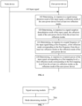
- FIG. 5 illustrates a flowchart of a method for zero-power communication according to some exemplary embodiments of the present disclosure.
- the method is applicable to a zero-power communication system, and the method includes the following processes.
- a node device transmits an input signal to a zero-power device.
- the zero-power device receives the input signal.
- the zero-power device supports at least two reflection modes.
- the zero-power device in the embodiments of the present disclosure is considered as a device that supports multiple reflection modes.
- the reflection mode refers to a mode composed of various technical features employed by the zero-power device in the process of performing zero-power communication.
- the reflection mode in some embodiments of the present disclosure is understood as an operating mode, a transmission mode of a reflection link, a backscattering mode, or a transmission mode.
- the reflection mode in the embodiments of the present disclosure not only corresponds to a situation in which the zero-power device perform backscattering communication; it also corresponds to a situation in which the zero-power device actively transmits a transmission signal.
- the "reflected signal" in the embodiments of the present disclosure is construed to be the "transmission signal" actively transmitted by the zero-power device.
- the at least two reflection modes are predefined in the communication protocol, the at least two reflection modes are configured on the network device side for the zero-power device, or the at least two reflection modes are customized by the zero-power device.
- the node device includes a network device, such as a base station; or a customer premise equipment (CPE).
- a network device such as a base station; or a customer premise equipment (CPE).
- CPE customer premise equipment
- the zero-power device determines, in response to a trigger of the input signal, a reflection mode of the zero-power device from at least two reflection modes.
- the zero-power device Upon receiving the input signal, the zero-power device selects or switches the reflection mode of the zero-power device from the at least two reflection modes.
- that the zero-power device determines the reflection mode of the zero-power device from the at least two reflection modes includes: selecting, by the zero-power device, a first reflection mode from the at least two reflection modes as the reflection mode of the zero-power device.
- selecting refers to an initial selection, which is a selection of the zero-power device in the case of an initial access, i.e., a first selection.
- the zero-power device prior to the initial selection, the zero-power device is not in an operating state and is not in any of the reflection modes, and in response to the trigger of the input signal, the zero-power device selects a first reflection mode from the at least two reflection modes as a post-access reflection mode.
- that the zero-power device determines the reflection mode of the zero-power device from the at least two reflection modes includes: switching, by the zero-power device, the reflection mode from a second reflection mode to the first reflection mode.
- switching refers to a re-selection, which is a selection by the zero-power device upon completion of an access, i.e., an n th selection, n being an integer greater than 1.
- the zero-power device prior to the switching, the zero-power device is in the second reflection mode, and in response to the trigger of the input signal, the zero-power device selects the first reflection mode from at least two reflection modes and switches from the second reflection mode to the first reflection mode.
- the trigger of the input signal described above refers to a trigger by a signal feature of the input signal, or the trigger of the input signal refers to a trigger by information acquired by demodulation of the input signal.
- that the zero-power device selects or switches the reflection mode of the zero-power device from at least two reflection modes in response to the trigger of the input signal includes the following.
- the zero-power device In response to the trigger of the input signal, specifies one of the at least two reflection modes for selecting or switching.
- the zero-power device determines to select or switch to a reflection mode a of the at least two reflection modes based on some information of the input signal.
- the at least two reflection modes have a selection order, and in response to the trigger of the input signal, the zero-power device determines one of the reflection modes to be selected or switched to accordingly based on the selection order.
- a next reflection mode to be selected by the zero-power device based on the selection order is the reflection mode a.
- the zero-power device selects the reflection mode a as a current reflection mode based on the selection order.
- the zero-power device supports at least two reflection modes, and triggered by the received input signal, the zero-power device is capable of selecting a reflection mode from the at least two reflection modes, such that the zero-power device meets different communication needs by performing the selection of the reflection mode.
- the input signal is defined.
- the input signal includes at least one of:
- the contents defined in the first reflection method include at least one of a type of information carried by the reflected signal or an operating frequency point of the reflected signal. That is, the activation signal is configured to activate the zero-power device to transmit the reflected signal carrying a specified type of information via an operating frequency point.
- the activation signal is not a mandatory signal in the zero-power communication system, and the zero-power communication system may transmit the reflected signal based on a predetermined reflection method without activation of the activation signal.
- the activation signal in the embodiments of the present disclosure is referred to as a trigger signal or a wake-up signal.
- the power sourcing signal, the carrier signal, and the activation signal are mutually independent; the power sourcing signal and the carrier signal are mutually coupled, and the power sourcing signal and the activation signal are mutually independent; the activation signal and the carrier signal are mutually coupled, and the activation signal and the power sourcing signal are mutually independent; the activation signal and the power sourcing signal are mutually coupled, and the activation signal and the carrier signal are mutually independent; or the power sourcing signal, the carrier signal, and the activation signal are mutually coupled.
- mutually independent means that signals are independent in at least one of an operating frequency, an operating time, or an operating spatial direction.
- mutually coupled means that signals are coupled in at least one of an operating frequency, an operating time, or an operating spatial direction.
- the power sourcing signal, the carrier signal, and the activation signal are in fact a combined single signal or a plurality of separated signals.
- a reflection mode is defined. Two different reflection modes differ in at least one of the following.
- the communication protocol type includes RFID; Bluetooth, such as Bluetooth low energy (BLE); wireless fidelity (Wi-Fi) 802.11ah; LTE; or narrow band Internet of things (NB-IoT).
- BLE Bluetooth low energy
- Wi-Fi wireless fidelity
- LTE Long Term Evolution
- NB-IoT narrow band Internet of things
- the packet size includes [x, y] bytes and [y, z] bytes.
- the above x, y, and z are unequal positive numbers, z is greater than y, and y is greater than x.
- the information type includes device information of the zero-power device, such as a tag identification (ID); sensing information of the zero-power device, such as temperature information and pressure information acquired using a sensor; security information, such as private information; and non-security information, such as information that is not private.
- ID tag identification
- sensing information of the zero-power device such as temperature information and pressure information acquired using a sensor
- security information such as private information
- non-security information such as information that is not private.
- the reflection period includes one reflection at every 100 ms and one reflection at every 500 ms.
- the data rate includes 10 kbps, 100 kbps, and 1000 kbps.
- the operating frequency includes 2.4 GHz, 900 MHz, and 800 MHz.
- the operating frequency includes 2.4 GHz, 900 MHz, or 800 MHz.
- Reflection mode 1 900 MHz supply signal/carrier signal/reflected signal + WiFi 802.11ah reflected signal.
- the power sourcing signal and the carrier signal in this reflection mode are the one and the same signal, which operates at 900 MHz, and the reflected signal operates at the same frequency as the carrier signal, which also operates at 900MHz; and, the reflected signal corresponds to the protocol type of Wi-Fi 802.11ah.
- Reflection mode 2 900 MHz power sourcing signal + 2.4 GHz carrier signal/reflected signal, Bluetooth BLE broadcast.
- the power sourcing signal and the carrier signal in this reflection mode are not the one and the same signal, the power sourcing signal operates at 900 MHz, and the carrier signal and the reflected signal operate at 2.4 GHz; and, the reflected signal corresponds to the protocol type of Bluetooth BLE.
- Reflection mode 3 2.4 GHz power sourcing signal/carrier signal/activation signal/reflected signal, Bluetooth BLE broadcast.
- the power sourcing signal, the carrier signal, and the activation signal in this reflection mode are the one and the same signal, which operates at 2.4 GHz, and the reflected signal operates at the same frequency as the carrier signal, which also operates at 2.4 GHz; and, the reflected signal corresponds to the protocol type of Bluetooth BLE.
- Reflection mode 4 the zero-power device transmits a reflected signal, such as a reflected signal with a tag ID, once a received carrier signal of the corresponding frequency meets a certain signal intensity requirement.
- the above-mentioned reflection mode 4 is understood as a normal reflection mode.
- Reflection mode 5 in addition to the carrier signal, an additional activation signal is required, and upon receiving and demodulating the activation signal correctly, the zero-power device then controls to transmit a reflected signal with safety information, such as temperature and heart rate.
- the above-described reflection mode 5 is understood as a safety reflection mode.
- FIG. 6 illustrates a flowchart of a method for zero-power communication according to some exemplary embodiments of the present disclosure.
- the method is applicable to a zero-power communication system, and the method includes the following processes.
- a node device transmits an input signal to a zero-power device.
- the zero-power device receives the input signal.
- the zero-power device determines, in response to a signal energy detection result of the incident signal, a reflection mode of the zero-power device from at least two reflection modes.
- the zero-power device Upon receiving the input signal, the zero-power device performs signal energy detection on the input signal to acquires the signal energy detection result. In the case that the signal energy detection result meets a trigger condition, the zero-power device performs selection or switching of the reflection mode of the zero-power device from the at least two reflection modes.
- the signal energy detection result includes at least one of an amplitude of the energy or a time-domain feature of the energy.
- the signal energy detection result is the amplitude of the energy.
- process 622 is alternatively implemented as follows: in response to the amplitude of the energy of the input signal reaching a first threshold, a first reflection mode corresponding to a first frequency is determined from the at least two reflection modes as the reflection mode of the zero-power device, wherein the first threshold is one threshold of at least one threshold that triggers determining the reflection mode.
- the zero-power device switches from the reflection mode b to the reflection mode a.
- the signal energy detection results is the time-domain feature of the energy.
- process 622 is alternatively implemented as follows: in response to the time-domain feature of the energy of the input signal being a first time-domain feature, a first reflection mode is determined as the reflection mode of the zero-power device from the at least two reflection modes based on an order indicated by a list of predefined reflection modes, wherein the list of predefined reflection modes includes at least two reflection modes, and the first time-domain feature is one time-domain feature of at least one time-domain feature that triggers determining the reflection mode.
- the zero-power device switches from the reflection mode b to reflection mode a.
- the zero-power device switches from the reflection mode b to the reflection mode a.
- the zero-power device determines, in response to a signal reception demodulation result of the input signal, the reflection mode of the zero-power device from the at least two reflection modes.
- the zero-power device Upon receiving the input signal, the zero-power device demodulates the input signal to acquire the signal reception demodulation result, and in the case that the signal reception demodulation result meets the trigger condition, the zero-power device selects or switches the reflection mode of the zero-power device from the at least two reflection modes. It should be understood that demodulation is generally the signal envelope detection.
- the signal reception demodulation result includes at least one of information acquired by demodulation or a phase conversion feature acquired by demodulation.
- the signal reception demodulation result is the information acquired by demodulation.
- process 624 is alternatively implemented as follows: in response to the information acquired by demodulating the input signal is first information, a first reflection mode corresponding to the first information is determined from the at least two reflection modes as the reflection mode of the zero-power device, wherein the first information is one of at least one information that triggers determining the reflection mode.
- the zero-power device switches from the reflection mode b to the reflection mode a.
- the signal reception demodulation result is the phase conversion feature acquired by demodulation.
- process 624 is alternatively implemented as follows: in response to the phase conversion feature acquired by demodulating the input signal is a first phase conversion feature, a first reflection mode is determined as the reflection mode of the zero-power device from the at least two reflection modes based on an order indicated by a list of predefined reflection modes, wherein the list of predefined reflection modes includes at least two reflection modes, and the first phase conversion feature is one of at least one phase conversion feature that triggers determining the reflection mode.
- the zero-power device switches from the reflection mode b to the reflection mode a.
- the zero-power device determines, in response to a signal frequency of the input signal being a first frequency, a first reflection mode corresponding to the first frequency from the at least two reflection modes as the reflection mode of the zero-power device.
- the first frequency is one of at least one frequency that triggers determining the reflection mode.
- the zero-power device Upon receiving the input signal, the zero-power device determines the signal frequency of the input signal and acquires that the signal frequency of the input signal is the first frequency, and in the case that the first frequency has a correspondence with the first reflection mode and the zero-power device is not currently in an operating state or the current reflection mode is not the first reflection mode, the zero-power device selects or switches to the first reflection mode as the reflection mode of the zero-power device.
- the frequency that triggers determining the reflection mode is a specific frequency other than an power sourcing frequency, a carrier frequency, and an activation frequency.
- the aforementioned power sourcing frequency, carrier frequency, and activation frequency are the same frequency or different frequencies.
- the zero-power device determines, in response to a transmit power of the input signal corresponding to a first mapping level, a first reflection mode corresponding to the first mapping level from the at least two reflection modes as the reflection mode of the zero-power device.
- the first mapping level is one mapping level of at least one mapping level that triggers determining the reflection mode.
- the zero-power device Upon receiving the input signal, the zero-power device determines the transmit power of the input signal and acquires that the transmit power of the input signal corresponds to the first mapping level, and in the case that the first mapping level has a correspondence with the first reflection mode and the zero-power device is not currently in an operating state or the current reflection mode is not the first reflection mode, the zero-power device selects or switches to the first reflection mode as the reflection mode of the zero-power device.
- a maximum value of the transmit power of the input signal is 33 dBm, which is adjusted by converting the value to a mapping level in every 2 dB step, and the zero-power device is controlled to reflect reflected signals in different reflection modes at different mapping levels.
- the aforementioned processes 622 to 628 are capable of controlling the reflection mode of the zero-power device individually or are combined to jointly control the reflection mode of the zero-power device.
- process 624 and process 628 jointly controlling the reflection mode of the zero-power device is given hereinafter.
- the transmit power is adjusted according to coarse adjustment in a large interval followed by fine adjustment in a small interval.
- Different transmit powers correspond to different power sourcing durations and different time delays for feedback, which determines the different reflection modes of the zero-power device.
- the zero-power device receives the downlink signal and demodulates the corresponding control information such as the signal amplitude.
- the control information determines the corresponding reflection mode of the zero-power device.
- the input signal triggering the zero-power device to perform the selection or switching of the reflection mode, such that the zero-power device performs the selection of the reflection mode more flexibly.
- FIG. 7 illustrates a block structural diagram of an apparatus for zero-power communication according to some exemplary embodiments of the present disclosure.
- the apparatus for zero-power communication is implemented as a zero-power device, or a part of a zero-power device.
- the apparatus includes a signal receiving module 702 and a mode determining module 704.
- the signal receiving module 702 is configured to receive an input signal.
- the mode determining module 704 is configured to determine a reflection mode of the apparatus from at least two reflection modes in response to a trigger of the input signal.
- the at least two different reflection modes differ in at least one of:
- the mode determining module 704 is configured to determine the reflection mode of the apparatus from the at least two reflection modes in response to a signal energy detection result of the input signal;
- the mode determining module 704 is configured to determine, in response to an amplitude of the energy of the input signal reaching a first threshold, a first reflection mode corresponding to a first frequency from the at least two reflection modes as the reflection mode of the apparatus, wherein the first threshold is one of at least one threshold that triggers determining the reflection mode; or the mode determining module 704 is configured to determine, in response to a time-domain feature of the energy of the input signal being a first time-domain feature, a first reflection mode from the at least two reflection modes as the reflection mode of the apparatus based on an order indicated by a list of predefined reflection modes, wherein the list of predefined reflection modes includes the at least two reflection modes, and the first time-domain feature is one of at least one time-domain feature that triggers determining the reflection mode.
- the mode determining module 704 is configured to determine, in response to information acquired by demodulating the input signal being first information, a first reflection mode corresponding to the first information from the at least two reflection modes as the reflection mode of the apparatus, wherein the first information is one of at least one information that triggers determining the reflection mode; or the mode determining module 704 is configured to determine, in response to a phase conversion feature acquired by demodulating the input signal being a first phase conversion feature, a first reflection mode as the reflection mode of the apparatus from the at least two reflection modes based on an order indicated by a list of predefined reflection modes, wherein the list of predefined reflection modes includes the at least two reflection modes, and the first phase conversion feature is one of at least one phase conversion feature that triggers determining the reflection mode.
- the input signal includes at least one of:
- the power sourcing signal, the carrier signal, and the activation signal are mutually independent; or
- the term "mutually independent" indicates that two signals are independent in at least one of: an operating frequency, an operating time, or an operating spatial direction.
- the term "mutually coupled" indicates that two signals are coupled in at least one of: an operating frequency, an operating time, or an operating spatial direction.
- the mode determining module 704 is configured to select a first reflection mode from the at least two reflection modes as the reflection mode of the zero-power device; or the mode determining module 704 is configured to switch the reflection mode of the zero-power device from a second reflection mode to the first reflection mode.
- FIG. 8 illustrates a block structural diagram of an apparatus for zero-power communication according to some exemplary embodiments of the present disclosure, which is implemented as a node device or a part of a node device.
- the apparatus includes a signal transmitting module 802.
- the signal transmitting module 802 is configured to transmit an input signal to a zero-power device, such that the zero-power device determines a reflection mode of the zero-power device from at least two reflection modes in response to a trigger of the input signal.
- the zero-power device supports the at least two reflection modes.
- the at least two different reflection modes differ in at least one of:
- the zero-power device determines the reflection mode of the zero-power device from the at least two reflection modes in response to a signal energy detection result of the input signal;
- the zero-power device determines, in response to an amplitude of the energy of the input signal reaching a first threshold, a first reflection mode corresponding to a first frequency from the at least two reflection modes as the reflection mode of the zero-power device, wherein the first threshold is one of at least one threshold that triggers determining the reflection mode; or the zero-power device determines, in response to a time-domain feature of the energy of the input signal being a first time-domain feature, a first reflection mode from the at least two reflection modes as the reflection mode of the zero-power device based on an order indicated by a list of predefined reflection modes, wherein the list of predefined reflection modes includes the at least two reflection modes, and the first time-domain feature is one of at least one time-domain feature that triggers determining the reflection mode.
- the zero-power device determines, in response to information acquired by demodulating the input signal being first information, a first reflection mode corresponding to the first information from the at least two reflection modes as the reflection mode of the zero-power device, wherein the first information is one of at least one information that triggers determining the reflection mode; or the zero-power device determines, in response to a phase conversion feature acquired by demodulating the input signal being a first phase conversion feature, a first reflection mode as the reflection mode of the zero-power device from the at least two reflection modes based on an order indicated by a list of predefined reflection modes, wherein the list of predefined reflection modes includes the at least two reflection modes and the first phase conversion feature is one of at least one phase conversion feature that triggers determining the reflection mode.
- the input signal includes at least one of:
- the power sourcing signal, the carrier signal, and the activation signal are mutually independent; or
- the term "mutually independent" indicates that two signals are independent in at least one of: an operating frequency, an operating time, or an operating spatial direction.
- the term "mutually coupled" indicates that two signals are coupled in at least one of: an operating frequency, an operating time, or an operating space direction.
- the zero-power device selects a first reflection mode from the at least two reflection modes as the reflection mode of the zero-power device; or the zero-power device switches the reflection mode from a second reflection mode to the first reflection mode.
- the node device includes: a network device; or a CPE.
- FIG. 9 illustrates a schematic structural diagram of a communication device according to some exemplary embodiments of the present disclosure.
- the communication device 900 includes a processor 901, a transceiver 902, and a memory 903.
- the processor 901 includes one or more processing cores, and the processor 901 runs various functional applications by running software programs and modules.
- the transceiver 902 is configured to receive and transmit information, and the transceiver 902 may be a communication chip.
- the memory 903 is configured to store at least one computer program.
- the processor 901 is configured to load and run the at least one computer program to perform the processes performed by the communication device in the method embodiments described above.
- the memory 903 is implemented by any type of volatile or non-volatile storage device or a combination thereof.
- the volatile or non-volatile storage device includes, but are not limited to: a random-access memory (RAM), a read-only memory (ROM), an erasable programmable read-only memory (EPROM), an electrically erasable programmable read-only memory (EEPROM), a flash memory, or other solid-state storage technologies, a compact disc read-only memory (CD-ROM), a high-density digital video disc (DVD), or other optical storage, tape cartridges, magnetic tapes, disk storage, or other magnetic storage devices.
- RAM random-access memory
- ROM read-only memory
- EPROM erasable programmable read-only memory
- EEPROM electrically erasable programmable read-only memory
- flash memory or other solid-state storage technologies
- CD-ROM compact disc read-only memory
- DVD high-density digital video disc
- the processor 901 and transceiver 902 involved in the embodiments of the present disclosure perform the processes performed by the zero-power device in the method shown in either of FIS. 5 and FIG. 6 above, which are not described herein.
- the processor 901 is configured to receive an input signal
- the transceiver 902 is configured to determine a reflection mode from at least two reflection modes in response to a trigger of the input signal.
- the processor 901 and the transceiver 902 involved in the embodiments of the present disclosure perform the processes performed by the node device in the method shown in either FIG. 5 and FIG. 6 above, which are not repeated herein.
- the transceiver 902 is configured to transmit an input signal to a zero-power device, such that the zero-power device determines a reflection mode of the zero-power device from at least two reflection modes in response to a trigger of the input signal, wherein the zero-power device supports the at least two reflection modes.
- a computer-readable storage medium stores at least one instruction, at least one program, a code set, or an instruction set therein.
- the at least one instruction, the at least one program, the code set, or the instruction set when loaded and executed by a processor, causes the processor to perform the method for zero-power communication as described above.
- a chip is provided.
- the chip includes at least one programmable logic circuit and/or at least one program instruction.
- the chip when running, is caused to perform the method for zero-power communication as described above.
- a computer program product when loaded and run on a processor of a computer device, causes the computer device to perform the method for zero-power communication as described above.
- system and “network” are often used interchangeably herein.
- the term “and/or” herein describes an associated relationship between associated objects, and indicates that three types of relationships.
- the phrase “A and/or B” means (A), (B), or (A and B).
- the symbol “/” herein generally indicates an "or” relationship between the associated objects.
- indicate mentioned in the embodiments of the present disclosure means a direct indication, an indirect indication, or an indication of an associated relationship.
- a instructing B may mean that that A indicates B directly, e.g., B may be acquired by A; or that A indicates B indirectly, e.g., A indicates C by which B may be acquired; or that an association is present between A and B.
- the term "correspondence" mentioned in the embodiments of the present disclosure may refer to a direct or indirect correspondence between two objects, an associated relationship between the two objects, an indicating and being indicated relationship, or a configuring and being configured relationship.
- predefined may be implemented by storing a corresponding code, form, or other means that may be used to indicate relevant information in a device (e.g., including a network device and a user device) in advance, and the specific ways of implementation are not limited in e the present disclosure.
- predefined may mean “defined in a protocol”.
- the "protocol” may refer to a standard protocol in the field of communication, such as an LTE protocol, an NR protocol, and relevant protocols to be applied in future communication systems, which are not limited herein.
Landscapes
- Engineering & Computer Science (AREA)
- Computer Networks & Wireless Communication (AREA)
- Signal Processing (AREA)
- Power Engineering (AREA)
- Quality & Reliability (AREA)
- Near-Field Transmission Systems (AREA)
Applications Claiming Priority (1)
| Application Number | Priority Date | Filing Date | Title |
|---|---|---|---|
| PCT/CN2022/079787 WO2023168605A1 (zh) | 2022-03-08 | 2022-03-08 | 零功耗通信的方法、装置、设备及介质 |
Publications (2)
| Publication Number | Publication Date |
|---|---|
| EP4492697A1 true EP4492697A1 (de) | 2025-01-15 |
| EP4492697A4 EP4492697A4 (de) | 2025-09-03 |
Family
ID=87936966
Family Applications (1)
| Application Number | Title | Priority Date | Filing Date |
|---|---|---|---|
| EP22930251.8A Pending EP4492697A4 (de) | 2022-03-08 | 2022-03-08 | Verfahren und vorrichtung zur nullleistungskommunikation, vorrichtung und medium |
Country Status (4)
| Country | Link |
|---|---|
| US (1) | US20240430813A1 (de) |
| EP (1) | EP4492697A4 (de) |
| CN (1) | CN118805338A (de) |
| WO (1) | WO2023168605A1 (de) |
Cited By (1)
| Publication number | Priority date | Publication date | Assignee | Title |
|---|---|---|---|---|
| US20250150154A1 (en) * | 2023-11-02 | 2025-05-08 | Qualcomm Incorporated | Passive or semi-passive device with polarization conversion capability |
Families Citing this family (2)
| Publication number | Priority date | Publication date | Assignee | Title |
|---|---|---|---|---|
| WO2025109587A1 (en) * | 2024-02-27 | 2025-05-30 | Lenovo (Singapore) Pte. Ltd. | Transmission and reception using multiple transmission reception points |
| CN120935805A (zh) * | 2024-05-10 | 2025-11-11 | 大唐移动通信设备有限公司 | 信息传输方法、装置及设备 |
Family Cites Families (6)
| Publication number | Priority date | Publication date | Assignee | Title |
|---|---|---|---|---|
| US8461966B2 (en) * | 2008-06-05 | 2013-06-11 | Micron Technology, Inc. | Systems and methods to determine kinematical parameters using RFID tags |
| WO2017027847A1 (en) * | 2015-08-12 | 2017-02-16 | University Of Washington | Backscatter devices and network systems incorporating backscatter devices |
| WO2018005855A1 (en) * | 2016-06-29 | 2018-01-04 | University Of Massachusetts | Systems, devices, and methods for providing power-proportional communication |
| CN108964751B (zh) * | 2018-07-30 | 2021-06-29 | 太原理工大学 | 一种利用环境rf无线充电的通信设备间的通信方法 |
| CN112055337B (zh) * | 2020-09-04 | 2023-01-17 | 深圳职业技术学院 | 一种物联网中的环境自适应终端工作模式调整方法 |
| CN113472382B (zh) * | 2021-06-29 | 2023-04-07 | Oppo广东移动通信有限公司 | 无线通信方法、装置、电子标签及存储介质 |
-
2022
- 2022-03-08 CN CN202280092554.1A patent/CN118805338A/zh active Pending
- 2022-03-08 WO PCT/CN2022/079787 patent/WO2023168605A1/zh not_active Ceased
- 2022-03-08 EP EP22930251.8A patent/EP4492697A4/de active Pending
-
2024
- 2024-09-04 US US18/824,246 patent/US20240430813A1/en active Pending
Cited By (2)
| Publication number | Priority date | Publication date | Assignee | Title |
|---|---|---|---|---|
| US20250150154A1 (en) * | 2023-11-02 | 2025-05-08 | Qualcomm Incorporated | Passive or semi-passive device with polarization conversion capability |
| US12597986B2 (en) * | 2023-11-02 | 2026-04-07 | Qualcomm Incorporated | Passive or semi-passive device with polarization conversion capability |
Also Published As
| Publication number | Publication date |
|---|---|
| CN118805338A (zh) | 2024-10-18 |
| US20240430813A1 (en) | 2024-12-26 |
| EP4492697A4 (de) | 2025-09-03 |
| WO2023168605A1 (zh) | 2023-09-14 |
Similar Documents
| Publication | Publication Date | Title |
|---|---|---|
| US20240430813A1 (en) | Method for ambient iot based communication, and device | |
| US8519847B2 (en) | Methodology, module, terminal, and system enabling scheduled operation of a radio frequency identification (RFID) subsystem and a wireless communication subsystem | |
| US20240243621A1 (en) | Information transmission method and apparatus, and device and storage medium | |
| US20090146791A1 (en) | Method, device, and system for "listen-before-talk" measurement to enable identifying of one or more unoccupied RF sub-bands | |
| US20100001843A1 (en) | Apparatus and method for integrated reader and tag | |
| US20250142471A1 (en) | Method for wireless communication, terminal device, and chip | |
| EP3996425B1 (de) | Rf-kommunikationsgeräte und betriebsmethoden | |
| US20250126572A1 (en) | Wireless communication method and device | |
| US20250294621A1 (en) | Random access methods and apparatuses, terminal and network device | |
| US20250294526A1 (en) | Communication method and apparatus, terminal, and network device | |
| US20250016604A1 (en) | Method and device for wireless communication | |
| US20250323683A1 (en) | Method for zero-power communication, zero-power device and network device | |
| US20260122576A1 (en) | Method for determining receiver parameter, zero-power device, and network device | |
| CN118830218A (zh) | 配置资源的方法、终端以及网络设备 | |
| US20240414767A1 (en) | Channel listening method and communication device | |
| US20120194323A1 (en) | Method for Wireless Data Transmission Between a Base Station and a Passive Transponder, as Well as a Passive Transponder | |
| WO2025055052A1 (zh) | 信息传输方法、装置、设备、介质和程序产品 | |
| US20250350435A1 (en) | Communication method and apparatus, terminal device, and network device | |
| US20250240777A1 (en) | Zero-power-consumption communication method and apparatus, and terminal device and network device | |
| US20250193837A1 (en) | Positioning method and apparatus, and communication device | |
| US20260143509A1 (en) | Method for communicating broadcast frames, zero-power device, and network device | |
| US20260121797A1 (en) | Method for measuring frequency errors, and device | |
| WO2025086063A1 (zh) | 数据传输方法、装置、设备及存储介质 | |
| WO2025166649A1 (zh) | 传输方法、装置、设备、介质和程序产品 | |
| Kim et al. | Development of zero-energy communication sensor tag system using ambient wi-fi signal |
Legal Events
| Date | Code | Title | Description |
|---|---|---|---|
| STAA | Information on the status of an ep patent application or granted ep patent |
Free format text: STATUS: THE INTERNATIONAL PUBLICATION HAS BEEN MADE |
|
| PUAI | Public reference made under article 153(3) epc to a published international application that has entered the european phase |
Free format text: ORIGINAL CODE: 0009012 |
|
| STAA | Information on the status of an ep patent application or granted ep patent |
Free format text: STATUS: REQUEST FOR EXAMINATION WAS MADE |
|
| 17P | Request for examination filed |
Effective date: 20241003 |
|
| AK | Designated contracting states |
Kind code of ref document: A1 Designated state(s): AL AT BE BG CH CY CZ DE DK EE ES FI FR GB GR HR HU IE IS IT LI LT LU LV MC MK MT NL NO PL PT RO RS SE SI SK SM TR |
|
| DAV | Request for validation of the european patent (deleted) | ||
| DAX | Request for extension of the european patent (deleted) | ||
| REG | Reference to a national code |
Ref country code: DE Ref legal event code: R079 Free format text: PREVIOUS MAIN CLASS: H04B0005000000 Ipc: G06K0019070000 |
|
| A4 | Supplementary search report drawn up and despatched |
Effective date: 20250804 |
|
| RIC1 | Information provided on ipc code assigned before grant |
Ipc: G06K 19/07 20060101AFI20250729BHEP Ipc: H04B 5/00 20240101ALI20250729BHEP Ipc: H04W 52/26 20090101ALI20250729BHEP Ipc: H04W 52/02 20090101ALI20250729BHEP Ipc: H04W 52/24 20090101ALI20250729BHEP Ipc: H02J 50/27 20160101ALI20250729BHEP |