EP4492709A1 - Procédé d'égalisation, dispositif d'égalisation, et système de réception - Google Patents
Procédé d'égalisation, dispositif d'égalisation, et système de réception Download PDFInfo
- Publication number
- EP4492709A1 EP4492709A1 EP22930948.9A EP22930948A EP4492709A1 EP 4492709 A1 EP4492709 A1 EP 4492709A1 EP 22930948 A EP22930948 A EP 22930948A EP 4492709 A1 EP4492709 A1 EP 4492709A1
- Authority
- EP
- European Patent Office
- Prior art keywords
- phase
- processing
- phase rotation
- equalization
- amount
- Prior art date
- Legal status (The legal status is an assumption and is not a legal conclusion. Google has not performed a legal analysis and makes no representation as to the accuracy of the status listed.)
- Pending
Links
Images




Classifications
-
- H—ELECTRICITY
- H04—ELECTRIC COMMUNICATION TECHNIQUE
- H04B—TRANSMISSION
- H04B11/00—Transmission systems employing ultrasonic, sonic or infrasonic waves
-
- H—ELECTRICITY
- H04—ELECTRIC COMMUNICATION TECHNIQUE
- H04L—TRANSMISSION OF DIGITAL INFORMATION, e.g. TELEGRAPHIC COMMUNICATION
- H04L27/00—Modulated-carrier systems
- H04L27/01—Equalisers
-
- H—ELECTRICITY
- H04—ELECTRIC COMMUNICATION TECHNIQUE
- H04L—TRANSMISSION OF DIGITAL INFORMATION, e.g. TELEGRAPHIC COMMUNICATION
- H04L25/00—Baseband systems
- H04L25/02—Details ; arrangements for supplying electrical power along data transmission lines
- H04L25/03—Shaping networks in transmitter or receiver, e.g. adaptive shaping networks
- H04L25/03006—Arrangements for removing intersymbol interference
- H04L25/03012—Arrangements for removing intersymbol interference operating in the time domain
- H04L25/03114—Arrangements for removing intersymbol interference operating in the time domain non-adaptive, i.e. not adjustable, manually adjustable, or adjustable only during the reception of special signals
- H04L25/03127—Arrangements for removing intersymbol interference operating in the time domain non-adaptive, i.e. not adjustable, manually adjustable, or adjustable only during the reception of special signals using only passive components
-
- H—ELECTRICITY
- H04—ELECTRIC COMMUNICATION TECHNIQUE
- H04L—TRANSMISSION OF DIGITAL INFORMATION, e.g. TELEGRAPHIC COMMUNICATION
- H04L25/00—Baseband systems
- H04L25/02—Details ; arrangements for supplying electrical power along data transmission lines
- H04L25/03—Shaping networks in transmitter or receiver, e.g. adaptive shaping networks
- H04L25/03006—Arrangements for removing intersymbol interference
- H04L25/03012—Arrangements for removing intersymbol interference operating in the time domain
- H04L25/03114—Arrangements for removing intersymbol interference operating in the time domain non-adaptive, i.e. not adjustable, manually adjustable, or adjustable only during the reception of special signals
- H04L25/03146—Arrangements for removing intersymbol interference operating in the time domain non-adaptive, i.e. not adjustable, manually adjustable, or adjustable only during the reception of special signals with a recursive structure
-
- H—ELECTRICITY
- H04—ELECTRIC COMMUNICATION TECHNIQUE
- H04L—TRANSMISSION OF DIGITAL INFORMATION, e.g. TELEGRAPHIC COMMUNICATION
- H04L25/00—Baseband systems
- H04L25/02—Details ; arrangements for supplying electrical power along data transmission lines
- H04L25/03—Shaping networks in transmitter or receiver, e.g. adaptive shaping networks
- H04L25/03006—Arrangements for removing intersymbol interference
- H04L25/03821—Inter-carrier interference cancellation [ICI]
-
- H—ELECTRICITY
- H04—ELECTRIC COMMUNICATION TECHNIQUE
- H04L—TRANSMISSION OF DIGITAL INFORMATION, e.g. TELEGRAPHIC COMMUNICATION
- H04L25/00—Baseband systems
- H04L25/02—Details ; arrangements for supplying electrical power along data transmission lines
- H04L25/03—Shaping networks in transmitter or receiver, e.g. adaptive shaping networks
- H04L25/03006—Arrangements for removing intersymbol interference
- H04L2025/03592—Adaptation methods
- H04L2025/03598—Algorithms
- H04L2025/03611—Iterative algorithms
- H04L2025/03636—Algorithms using least mean square [LMS]
Definitions
- the present invention relates to an equalization method, an equalization device and a receiving system.
- a multi-reception channel adaptive equalizer may be used (see, for example, Non Patent Literature 1 and Non Patent Literature 2).
- This adaptive equalizer is called a multi-channel decision feedback equalizer (DFE).
- DFE multi-channel decision feedback equalizer
- This adaptive equalizer includes a finite impulse response (FIR) filter for each reception channel.
- the adaptive equalizer performs waveform equalization by combining output values obtained by FIR filter calculation for each reception channel across all reception channels. Furthermore, the adaptive equalizer calculates an error between an equalizer output obtained by the above-described equalization processing and a desired signal (or provisional determination value).
- the adaptive equalizer adaptively controls coefficients of the FIR filter using an adaptive algorithm such as least mean square (LMS) or recursive least square (RLS) on the basis of the error. Accordingly, the adaptive equalizer is caused to follow the variation in multipath strength and the variation in direction of arrival that occur in a data frame.
- LMS least mean square
- RLS recursive least square
- the adaptive equalizer includes a digital phase-lock loop (DPLL) inside.
- DPLL digital phase-lock loop
- the adaptive equalizer uses the DPLL to adaptively compensate for Doppler frequency fluctuations caused by external factors such as ship rocking.
- a DPLL of a conventional multi-channel DFE detects a phase lead amount (or delay amount) on the basis of a comparison between a phase of an output value of an FIR filter included in each reception channel and a phase of a desired signal, and smooths the detected phase amount using a loop filter. Accordingly, Doppler frequency fluctuations of each reception channel are estimated and compensated for by correcting the phase of the reception signal. Since the DPLL is performed completely independently for each reception channel, the DPLL operates without problems even if the Doppler frequency fluctuations of each reception channel are different.
- SINR signal-to-interference-plus-noise ratio
- an object of the present invention is to provide an equalization method, an equalization device, and a receiving system capable of improving demodulation performance in an environment where an influence of noise is large.
- an equalization method including: a phase rotation step of inputting, from one or more subarrays including a set of the plurality of elements having a strong correlation in a Doppler frequency transition, a signal received by each of the plurality of elements, and performing, on the reception signal, phase rotation processing of a phase rotation amount calculated for the subarray to which the element that has received the reception signal belongs; an equalization step of performing equalization processing on the reception signal subjected to the phase rotation processing; and a calculation step of averaging phase amounts of the signals received by the elements belonging to the subarray for each of the subarrays, and calculating the phase rotation amount for performing phase compensation by the phase rotation processing using the averaged phase amount.
- an equalization device including: a phase rotation unit configured to input, from one or more subarrays including a set of the plurality of elements having a strong correlation in a Doppler frequency transition, a signal received by each of the plurality of elements, and to perform, on the reception signal, phase rotation processing of a phase rotation amount calculated for the subarray to which the element that has received the reception signal belongs; an equalization unit configured to perform equalization processing on the reception signal subjected to the phase rotation processing; and a calculation unit configured to average phase amounts of the signals received by the elements belonging to the subarray for each of the subarrays, and to calculate the phase rotation amount for performing phase compensation by the phase rotation processing using the averaged phase amount.
- a receiving system including: one or more subarrays including a set of a plurality of elements having a strong correlation in a Doppler frequency transition; a phase rotation unit configured to perform, on a signal received by each of the elements, phase rotation processing of a phase rotation amount calculated for the subarray to which the element that has received the reception signal belongs; an equalization unit configured to perform equalization processing on the reception signal subjected to the phase rotation processing; and a calculation unit configured to average phase amounts of the signals received by the elements belonging to the subarray for each of the subarrays, and to calculate the phase rotation amount for performing phase compensation by the phase rotation processing using the averaged phase amount.
- Fig. 7 is a diagram illustrating a configuration of an equalizer 90 using the related art.
- the equalizer 90 is a multi-channel DFE.
- the number of reception channels of the equalizer 90 is N (N is an integer of 2 or more).
- the signal input to the equalizer 90 is, for example, a sound wave received by an array of N receivers arranged in a row.
- the equalizer 90 receives input signals for each channel.
- An n-th channel is referred to as a channel ch(n), and an input signal of the channel ch(n) is referred to as an input R(n).
- n is an integer 1 or more and N or less.
- the equalizer 90 includes N phase rotation units 91, N feedforward filters (FF-filters) 92, an adder 93, a feedback filter (FB-filter) 94, an acquisition unit 95, an error calculation unit 96, an adaptive algorithm unit 97, and N DPLLs 98.
- the phase rotation unit 91, the FF-filter 92, and the DPLL 98 corresponding to the channel ch(n) are referred to as a phase rotation unit 91-n, an FF-filter 92-n, and a DPLL 98-n, respectively.
- the phase rotation unit 91-n performs phase rotation processing on the input R(n).
- the FF-filter 92-n performs FF-filter processing on the input R(n) subjected to the phase rotation processing, and outputs a waveform-equalized signal p k,n . k is a sample number.
- the adder 93 combines signals p k,1 to p k,N individually processed for each of channels ch(1) to ch(N).
- the adder 93 may also combine an output q k of the FB-filter 94 therewith in addition to the signals p k,1 to p k,N . This combining is shown by the following Formula (1).
- subscript k represents a k-th sample output after the equalizer 90 operates.
- the acquisition unit 95 performs symbol determination on the equalizer output y k or reads out training data stored in advance, thereby obtaining a desired signal d k corresponding to the equalizer output y k .
- the equalizer output y k can also be considered as an estimated value obtained when the desired signal d k is transmitted.
- the equalizer 90 outputs an equalizer output y k for subsequent processing.
- the error calculation unit 96 obtains an error signal e k on the basis of a difference between the equalizer output y k and the desired signal d k .
- the adaptive algorithm unit 97 drives the adaptive algorithm on the basis of the error signal e k to update the filter coefficients of the FF-filters 92-1 to 92-N and the coefficients of the FB-filter 94.
- the DPLL 98-1 to the DPLL 98-N detect the phase amount of the signal p k,n .
- the phase amount of the signal p k,n is the phase lead amount (or phase delay amount) of the signal p k,n from the desired signal d k .
- a calculation formula for detecting the phase value, which is the value of the phase amount of the signal p k,n is as follows.
- the DPLL 98-1 to the DPLL 98-N may calculate a phase detection value g k,n of the signal p k,n by applying any one of Formulas (2) and (3).
- Im represents an imaginary part.
- * on the right shoulder indicates a complex conjugate.
- the DPLL 98-n applies loop filter processing to the phase detection value g k,n to obtain a phase rotation amount exp (j ⁇ k+1,n ) of the channel ch(n) in the (k+1)-th repetition.
- ⁇ k+1,n is calculated using the following Formula (4).
- K 1 and K 2 are loop filter coefficients of the DPLL 98.
- the phase rotation amount exp(j ⁇ k+1,n ) calculated in each iteration is an estimation amount individually calculated for each channel ch(n).
- the DPLL 98-n outputs the calculated phase rotation amount exp(j ⁇ k+1,n ) to the phase rotation unit 91-n.
- the phase rotation unit 91-n gives the phase rotation amount exp (j ⁇ k+1,n ) to the (k+1) -th sample of the input R(n) .
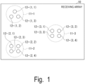
- Fig. 1 is a diagram illustrating a configuration of a receiving array 10 used in an embodiment of the present invention.
- the receiving array 10 includes one or more subarrays 11.
- Each subarray 11 includes a set of receivers 12 having two or more elements.
- the receiver 12 is also referred to as an element.
- N sub (N sub is an integer of 1 or more) subarrays 11 included in the receiving array 10 are referred to as subarrays 11-1 to 11-N sub , respectively.
- the M n receivers 12 arranged in the subarray 11-n are referred to as receivers 12-(n,1) to 12-(n,M n ), respectively.
- n is an integer of 1 or more and N sub or less.
- M n is an integer of 2 or more.
- the receiving array 10 illustrated in Fig. 1 includes a subarray 11-1, a subarray 11-2, and a subarray 11-3.
- the subarray 11-1 includes three elements of receivers 12-(1,1) to 12-(1,3).
- the subarray 11-2 includes four elements of receivers 12-(2,1) to 12-(2,4).
- the subarray 11-3 includes four elements of receivers 12-(3,1) to 12-(3,4).
- the receivers 12 constituting the respective subarrays 11 are physically very close to each other.
- the plurality of receivers 12 constituting the subarray 11 have a strong positive correlation in a Doppler frequency transition.
- the distance between the plurality of receivers 12 constituting one subarray 11 may be set to be within a threshold value.
- the threshold value is determined on the basis of, for example, a distance at which the subarrays 11 have a predetermined or more positive correlation in a Doppler frequency transition.
- the subarrays 11 are installed at positions separated from each other.
- the Doppler frequency fluctuations that occur in each of the different subarrays 11 may differ.
- the three receivers 12-(1,1) to 12-(1,3) are arranged at positions very physically close to each other in the subarray 11-1, it can be considered that these receivers 12-(1,1) to 12-(1,3) are subjected to the same Doppler frequency fluctuation.
- Fig. 2 is a diagram illustrating an installation example of the subarray 11.
- Fig. 2 illustrates a front view of a ship 20.
- a subarray 11-1 is installed on one of both sides of the ship 20, and a subarray 11-2 is installed on the other side.
- a transmitter 30 is installed immediately below the ship 20.
- the subarray 11-1 moves away from the transmitter 30, as indicated by arrow A1. Therefore, the Doppler frequencies of receivers 12-(1,1) to 12-(1,M 1 ) in the subarray 11-1 uniformly become low.
- the subarray 11-2 moves to approach the transmitter 30 as indicated by arrow A2. Therefore, the Doppler frequencies of receivers 12-(2,1) to 12-(2,M 2 ) in the subarray 11-2 uniformly become high.
- phase amount detected for each of the subarrays 11 is averaged and the same DPLL is applied for each of the subarrays 11 using this property, an averaging effect against noise will occur, making it more robust against phase noise.
- Fig. 3 is a diagram illustrating a configuration of an equalizer 50.
- the receiving system of the present embodiment includes the receiving array 10 illustrated in Fig. 1 , an analog-to-digital conversion unit (not illustrated), and an equalizer 50 illustrated in Fig. 3 .
- the analog-to-digital conversion unit converts a signal received by each element of the receiving array 10 from an analog signal to a digital signal and outputs the digital signal to the equalizer 50.
- the equalizer 50 performs signal equalization by digital filter processing.
- the equalizer 50 includes L phase rotation units 51, L FF-filters 52, an adder 53, an FB-filter 54, an acquisition unit 55, an error calculation unit 56, an adaptive algorithm unit 57, and N sub DPLLs 58.
- the equalizer 50 receives a signal from each of the N sub subarrays 11.
- the n-th (in the case of the equalizer 50, n is an integer of 1 or more and N sub or less) subarray 11-n includes M n receivers 12-(n,1) to 12-(n,M n ). That is, each subarray 11-n has M n channels.
- M 1 to M Nsub do not necessarily all have to be the same number.
- Channels belonging to the receivers 12-(n,1) to 12-(n,M n ) of the subarray 11-n are referred to as channels ch(n,1) to ch(n,M n ), respectively.
- the input signals of the channels ch(n,1) to ch(n,M n ) are referred to as inputs R(n,1) to R(n,M n ) .
- the input R(n,m n ) is a signal obtained by converting the signal of the channel ch(n,m n ) received by the receiver 12-(n,m n ) from an analog signal to a digital signal (m n is an integer of 1 or more and M n or less).
- the equalizer 50 includes a phase rotation unit 51 and an FF-filter 52 corresponding to each of the receivers 12-(n,m n ).
- the phase rotation unit 51 and the FF-filter 52 corresponding to the receiver 12-(n,m n ) are referred to as a phase rotation unit 51-(n,m n ) and an FF-filter 52-(n,m n ), respectively.
- the phase rotation unit 51-(n,m n ) performs phase rotation processing on the input R(n,m n ) of the channel ch(n,m n ).
- the FF-filter 52-(n,m n ) performs the FF-filter processing on the k-th sample of the input R(n,m n ) on which the phase rotation processing has been performed, and outputs a signal p k , (n,m_n) .
- the equalizer 50 includes N sub DPLLs 58 corresponding to the respective subarrays 11.
- the DPLL 58 corresponding to the subarray 11-n is referred to as a DPLL 58-n.
- the other components of the equalizer 50 are similar to those of the conventional equalizer 90 illustrated in Fig. 7 . That is, the functions of the adder 53, the FB-filter 54, the acquisition unit 55, the error calculation unit 56, and the adaptive algorithm unit 57 are similar to the functions of the adder 93, the FB-filter 94, the acquisition unit 95, the error calculation unit 96, and the adaptive algorithm unit 97 of the equalizer 90.
- the adder 53 combines the signals p k , (1,1) to p k ,( Nsub,M_N_sub) output from the L FF-filters 52- (1, 1) to 52- (N sub ,M N_sub ).
- the adder 53 may also combine an output q k of the FB-filter 54 therewith.
- the DPLL 58-n obtains the phase detection value using the sum of the signals p k , (n,1) to p k , (n,M_n) which are the outputs from the FF-filters 52-(n,1) to 52-(n,M n ) belonging to the subarray 11-n.
- the DPLL 58-n calculates the phase detection value g k,n using the following Formula (5). [Math.
- the DPLL 58-n may calculate the phase detection value g k,n using the following Formula (6) obtained by extending the modification of Non Patent Literature 2.
- Sub Array: n in the formula is a set of channel numbers of the receivers 12-(n,1) to 12-(n,M n ) belonging to the subarray 11-n.
- the phase detection value g k,n corresponds to an average of the phase amounts of the received signals by the elements belonging to the subarray 11-n.
- the DPLL 58-n may calculate the phase detection value g k,n using the following Formula (7) to average the detection phases of the signals p k , (n,1) to pk, (n,M_n).
- Formula (7) to average the detection phases of the signals p k , (n,1) to pk, (n,M_n).
- the DPLL 58-n may calculate the phase detection value g k,n using the following Formula (8).
- Formula (8) similarly provides an averaging effect for noise.
- ⁇ m is an averaging weight.
- ⁇ m 1/M n , but other values may be used.
- the DPLL 58-n may directly calculate the phase detection value g k,n approximately from the equalizer output y k and the desired signal d k using Formula (9).
- Formula (6) becomes the following Formula (10) .
- the DPLL 58-n may directly calculate the phase detection value g k,n approximately from the equalizer output y k and the desired signal d k using Formula (10).
- the DPLL 58-n gives the same phase rotation amount to all the input channels ch(n,1) to ch(n,M n ) connected to the subarray 11-n. That is, the DPLL 58-n outputs the calculated phase rotation amount to the phase rotation units 51-(n,1) to 51-(n,M n ).
- the DPLL 58-n obtains the phase rotation amount exp (j ⁇ k+1,n ) of the (k+1) -th symbol using ⁇ k+1,n calculated by the following Formula (11) . [Math.
- K 1 (n) and K 2 (n) are loop filter coefficients of the DPLL 58-n.
- the update formula for giving ⁇ k+1,n may be an algorithm that automatically optimizes loop filter coefficients such as a Kalman filter method.
- the Kalman filter method is described, for example, in Reference Literature 1.
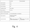
- FIG. 4 is a diagram illustrating a table describing experimental specifications. This test was performed on the equalizer 90 of the related art and the equalizer 50 of the present embodiment under the same conditions except for performing the DPLL.
- Fig. 5 is a diagram illustrating an experimental system. As illustrated in Fig. 5 , the transmission system was suspended and fixed at a water depth of 200 m. A reception point P1 is a receiving array 10 on a ship. Four subarrays 11 each including a four-element receiver 12 were arranged at 5 m intervals on a ship. That is, a total of 16 elements were arranged. The spacing of the four receivers 12 in each subarray 11 is 5 cm.
- the reception point P1 was fixedly installed on the ship side to have a water depth of 2 m, and the ship sailed at an average speed of 6 knots on the circling course as illustrated in Fig. 5 .
- the transmission system periodically transmitted packets at 5 seconds intervals from a transmission point P2.
- the reception point P1 performed reception and collected packets. Reception processing was performed on the collected packet as follows.
- the training data series was placed at the beginning of the frame.
- the filter coefficients were initially converged at sections of the training series.
- the symbol provisionally determined for each equalization was used, and the adaptive filter was operated to follow the variation of the transmission path.
- the DPLL was operated in parallel to follow the phase variation.
- the conventional equalizer 90 was updated using Formula (3) of the scheme according to Non Patent Literature 2, and the configuration of the present embodiment was updated using Formula (6). All processing other than the equalization block, such as synchronization, was the same.
- Fig. 6 is a diagram illustrating experimental results.
- the horizontal axis represents the input SNR, and the vertical axis represents the SNR at the equalizer output.
- a circle mark indicates a packet that has been successfully demodulated (error-free packet), and a cross mark indicates a packet that has failed to be demodulated (error packet).
- Fig. 6(a) illustrates a result of the equalizer 90 using the DPLL scheme of the related art
- Fig. 6(b) illustrates a result of the equalizer 50 using the DPLL scheme of the present embodiment.
- the present embodiment was clearly improved as compared with the related art. Therefore, it was shown that the DPLL scheme of the present embodiment is effective.
- a plurality of elements in physically similar environments are grouped into a subarray.
- the equalizer performs equalization by comparing d k obtained by combining the desired signal of each channel across all channels with y k obtained by combining the FIR output of each channel across all channels.
- the equalizer executes the DPLL algorithm for each subarray using e k which is a result of phase comparison between d k and y k . That is, the equalizer performs phase compensation for each subarray. Accordingly, since the noise is averaged and canceled, the phase compensation accuracy is improved, and further, the demodulation performance is improved.
- an analog PLL can be used instead of the DPLL.
- the equalizer converts a phase detection value obtained by performing phase detection by comparison between the symbol determination value and the equalizer output into an analog amount, and feeds back the analog amount to an analog PLL device.
- An analog PLL device performs similar processing to the above-described DPLL.
- the receiving system includes a receiving array and an equalization device.
- the receiving array has one or more subarrays.
- Each subarray includes a set of a plurality of elements having a strong positive correlation in a Doppler frequency transition.
- a set of a plurality of elements having a strong correlation in a Doppler frequency transition is, for example, a set of a plurality of elements which are close together.
- the equalization device is, for example, the equalizer 50 of the embodiment.
- the equalization device includes a phase rotation unit, an equalization unit, and a calculation unit.
- the phase rotation unit performs, on a reception signal received by each element of the receiving array, phase rotation processing of a phase rotation amount calculated for the subarray to which an element that has received the reception signal belongs.
- the equalization unit performs equalization processing on the reception signal subjected to the phase rotation processing.
- the equalization unit is, for example, the FF-filter 52 of the embodiment.
- the calculation unit averages phase amounts of the signals received by the elements belonging to the subarray for each subarray, and calculates the phase rotation amount for performing phase compensation by the phase rotation processing using the averaged phase amount.
- the calculation unit is, for example, the error calculation unit 56 and the DPLL 58 of the embodiment.
- the calculation unit may apply loop filter processing to the phase amount to calculate the phase rotation amount for each subarray.
- the calculation unit may perform comparison processing of comparing a composite signal obtained by combining all the reception signals after the equalization processing with a desired signal, phase amount calculation processing of calculating an averaged phase amount on the basis of a comparison result of the comparison processing and a result of summing the reception signals after the equalization processing of each of the elements belonging to the subarray for each subarray, and phase rotation amount calculation processing of smoothing the averaged phase amount of each of a plurality of symbols to calculate the phase rotation amount for each subarray.
- the phase amount calculation processing is, for example, Formulas (5) and (6) of the embodiment, and the phase rotation amount calculation processing is, for example, Formula (11) of the embodiment.
- the calculation unit may perform comparison processing of comparing a composite signal obtained by combining all the reception signals after the equalization processing with a desired signal, phase amount calculation processing of averaging phase amounts obtained on the basis of a comparison result of the comparison processing and the reception signals after the equalization processing of the respective elements belonging to the subarray for each subarray, and phase rotation amount calculation processing of smoothing the averaged phase amount of each of a plurality of symbols to calculate the phase rotation amount for each subarray.
- the phase amount calculation processing is, for example, Formulas (7) and (8) of the embodiment, and the phase rotation amount calculation processing is, for example, Formula (11) of the embodiment.
- the calculation unit may perform phase amount calculation processing of calculating an averaged phase amount on the basis of multiplication of a composite signal obtained by combining all the reception signals after the equalization processing by a complex conjugate of a desired signal, and phase rotation amount calculation processing of smoothing the averaged phase amount of each of a plurality of symbols to calculate the phase rotation amount.
- the phase amount calculation processing is, for example, Formulas (9) and (10) of the embodiment, and the phase rotation amount calculation processing is, for example, Formula (11) of the embodiment.
Landscapes
- Engineering & Computer Science (AREA)
- Computer Networks & Wireless Communication (AREA)
- Signal Processing (AREA)
- Power Engineering (AREA)
- Cable Transmission Systems, Equalization Of Radio And Reduction Of Echo (AREA)
Applications Claiming Priority (1)
| Application Number | Priority Date | Filing Date | Title |
|---|---|---|---|
| PCT/JP2022/011096 WO2023170968A1 (fr) | 2022-03-11 | 2022-03-11 | Procédé d'égalisation, dispositif d'égalisation, et système de réception |
Publications (2)
| Publication Number | Publication Date |
|---|---|
| EP4492709A1 true EP4492709A1 (fr) | 2025-01-15 |
| EP4492709A4 EP4492709A4 (fr) | 2025-12-03 |
Family
ID=87936511
Family Applications (1)
| Application Number | Title | Priority Date | Filing Date |
|---|---|---|---|
| EP22930948.9A Pending EP4492709A4 (fr) | 2022-03-11 | 2022-03-11 | Procédé d'égalisation, dispositif d'égalisation, et système de réception |
Country Status (4)
| Country | Link |
|---|---|
| US (1) | US12568007B2 (fr) |
| EP (1) | EP4492709A4 (fr) |
| JP (1) | JP7773096B2 (fr) |
| WO (1) | WO2023170968A1 (fr) |
Families Citing this family (1)
| Publication number | Priority date | Publication date | Assignee | Title |
|---|---|---|---|---|
| US12176628B2 (en) * | 2022-04-25 | 2024-12-24 | Qualcomm Incorporated | Signaling for z-rotation estimation |
Family Cites Families (3)
| Publication number | Priority date | Publication date | Assignee | Title |
|---|---|---|---|---|
| JP2001136114A (ja) * | 1999-11-02 | 2001-05-18 | Nec Corp | 水中通信復調器 |
| US6687188B2 (en) * | 2002-05-14 | 2004-02-03 | The United States Of America As Represented By The Secretary Of The Navy | Underwater telemetry apparatus and method |
| HK1255451A1 (zh) * | 2015-07-31 | 2019-08-16 | Teledyne Instruments, Inc. | 小孔径声波速度传感器 |
-
2022
- 2022-03-11 EP EP22930948.9A patent/EP4492709A4/fr active Pending
- 2022-03-11 JP JP2024505849A patent/JP7773096B2/ja active Active
- 2022-03-11 US US18/843,570 patent/US12568007B2/en active Active
- 2022-03-11 WO PCT/JP2022/011096 patent/WO2023170968A1/fr not_active Ceased
Also Published As
| Publication number | Publication date |
|---|---|
| JPWO2023170968A1 (fr) | 2023-09-14 |
| JP7773096B2 (ja) | 2025-11-19 |
| US12568007B2 (en) | 2026-03-03 |
| US20250184192A1 (en) | 2025-06-05 |
| EP4492709A4 (fr) | 2025-12-03 |
| WO2023170968A1 (fr) | 2023-09-14 |
Similar Documents
| Publication | Publication Date | Title |
|---|---|---|
| EP1971061B1 (fr) | Dispositif de communication sans fil | |
| US11652557B2 (en) | Turbo receivers for multiple-input multiple-output underwater acoustic communications | |
| US6574293B1 (en) | Receivers and methods for reducing interference in radio communications | |
| CN105207964B (zh) | 一种基于单矢量传感器的水声自适应判决反馈均衡方法 | |
| US11750299B2 (en) | Communication apparatus and communication method | |
| JP4869142B2 (ja) | アダプティブアンテナ | |
| CN113411278A (zh) | 基于接收阵的低频水声通信的均衡处理方法 | |
| EP2761779B1 (fr) | Suivi de phase différentielle en présence d'interférences inconnues | |
| EP4492709A1 (fr) | Procédé d'égalisation, dispositif d'égalisation, et système de réception | |
| Perrine et al. | Doppler estimation and correction for shallow underwater acoustic communications | |
| Oberg et al. | Underwater communication link with iterative equalization | |
| JP5178632B2 (ja) | Ofdmアレー受信装置 | |
| Cuji et al. | High-Rate Information Transmission for Underwater Channels: Path-Specific Beamforming and Doppler Compensation | |
| US20020167999A1 (en) | Equalizer, receiver, and equalization method and reception method | |
| JP7769264B2 (ja) | 受信方法、同期装置及び受信装置 | |
| JP4772462B2 (ja) | 受信機 | |
| WO2024166377A1 (fr) | Dispositif de communication, procédé de communication, et programme | |
| EP2015468A1 (fr) | Combineur de bande pour liens radio numériques | |
| US20240259111A1 (en) | Receiving apparatus and receiving method | |
| JP2009290763A (ja) | Ofdm信号合成用受信装置および中継装置 | |
| Girija et al. | Fractional weighted ZF equalizer: A novel approach for channel equalization in MIMO-OFDM system under impulse noise environment | |
| JP2868012B1 (ja) | 受信方法および受信装置 | |
| Mendoza et al. | Interference rejection using a hybrid of a constant modulus algorithm and the spectral correlation discriminator | |
| JP5337746B2 (ja) | Ofdm信号合成用受信装置及び中継装置 | |
| JP2006222836A (ja) | 受信装置、受信回路、受信方法及び受信プログラム |
Legal Events
| Date | Code | Title | Description |
|---|---|---|---|
| STAA | Information on the status of an ep patent application or granted ep patent |
Free format text: STATUS: THE INTERNATIONAL PUBLICATION HAS BEEN MADE |
|
| PUAI | Public reference made under article 153(3) epc to a published international application that has entered the european phase |
Free format text: ORIGINAL CODE: 0009012 |
|
| STAA | Information on the status of an ep patent application or granted ep patent |
Free format text: STATUS: REQUEST FOR EXAMINATION WAS MADE |
|
| 17P | Request for examination filed |
Effective date: 20240903 |
|
| AK | Designated contracting states |
Kind code of ref document: A1 Designated state(s): AL AT BE BG CH CY CZ DE DK EE ES FI FR GB GR HR HU IE IS IT LI LT LU LV MC MK MT NL NO PL PT RO RS SE SI SK SM TR |
|
| DAV | Request for validation of the european patent (deleted) | ||
| DAX | Request for extension of the european patent (deleted) | ||
| RAP3 | Party data changed (applicant data changed or rights of an application transferred) |
Owner name: NTT, INC. |
|
| A4 | Supplementary search report drawn up and despatched |
Effective date: 20251105 |
|
| RIC1 | Information provided on ipc code assigned before grant |
Ipc: H04B 11/00 20060101AFI20251030BHEP Ipc: H04L 25/03 20060101ALI20251030BHEP |