EP4492736A1 - Kommunikationssystem und verfahren - Google Patents
Kommunikationssystem und verfahren Download PDFInfo
- Publication number
- EP4492736A1 EP4492736A1 EP23184546.2A EP23184546A EP4492736A1 EP 4492736 A1 EP4492736 A1 EP 4492736A1 EP 23184546 A EP23184546 A EP 23184546A EP 4492736 A1 EP4492736 A1 EP 4492736A1
- Authority
- EP
- European Patent Office
- Prior art keywords
- interface
- controller
- buffer unit
- unit
- rate
- Prior art date
- Legal status (The legal status is an assumption and is not a legal conclusion. Google has not performed a legal analysis and makes no representation as to the accuracy of the status listed.)
- Pending
Links
Images


Classifications
-
- H—ELECTRICITY
- H04—ELECTRIC COMMUNICATION TECHNIQUE
- H04L—TRANSMISSION OF DIGITAL INFORMATION, e.g. TELEGRAPHIC COMMUNICATION
- H04L12/00—Data switching networks
- H04L12/28—Data switching networks characterised by path configuration, e.g. LAN [Local Area Networks] or WAN [Wide Area Networks]
- H04L12/40—Bus networks
- H04L12/4013—Management of data rate on the bus
-
- H—ELECTRICITY
- H04—ELECTRIC COMMUNICATION TECHNIQUE
- H04L—TRANSMISSION OF DIGITAL INFORMATION, e.g. TELEGRAPHIC COMMUNICATION
- H04L12/00—Data switching networks
- H04L12/28—Data switching networks characterised by path configuration, e.g. LAN [Local Area Networks] or WAN [Wide Area Networks]
- H04L12/40—Bus networks
- H04L12/40006—Architecture of a communication node
- H04L12/40013—Details regarding a bus controller
-
- H—ELECTRICITY
- H04—ELECTRIC COMMUNICATION TECHNIQUE
- H04L—TRANSMISSION OF DIGITAL INFORMATION, e.g. TELEGRAPHIC COMMUNICATION
- H04L12/00—Data switching networks
- H04L12/28—Data switching networks characterised by path configuration, e.g. LAN [Local Area Networks] or WAN [Wide Area Networks]
- H04L12/40—Bus networks
- H04L12/40006—Architecture of a communication node
- H04L12/40032—Details regarding a bus interface enhancer
-
- H—ELECTRICITY
- H04—ELECTRIC COMMUNICATION TECHNIQUE
- H04L—TRANSMISSION OF DIGITAL INFORMATION, e.g. TELEGRAPHIC COMMUNICATION
- H04L49/00—Packet switching elements
- H04L49/15—Interconnection of switching modules
-
- H—ELECTRICITY
- H04—ELECTRIC COMMUNICATION TECHNIQUE
- H04L—TRANSMISSION OF DIGITAL INFORMATION, e.g. TELEGRAPHIC COMMUNICATION
- H04L12/00—Data switching networks
- H04L12/28—Data switching networks characterised by path configuration, e.g. LAN [Local Area Networks] or WAN [Wide Area Networks]
- H04L12/40—Bus networks
- H04L2012/40208—Bus networks characterized by the use of a particular bus standard
- H04L2012/40215—Controller Area Network CAN
-
- H—ELECTRICITY
- H04—ELECTRIC COMMUNICATION TECHNIQUE
- H04L—TRANSMISSION OF DIGITAL INFORMATION, e.g. TELEGRAPHIC COMMUNICATION
- H04L12/00—Data switching networks
- H04L12/28—Data switching networks characterised by path configuration, e.g. LAN [Local Area Networks] or WAN [Wide Area Networks]
- H04L12/40—Bus networks
- H04L2012/40267—Bus for use in transportation systems
- H04L2012/40273—Bus for use in transportation systems the transportation system being a vehicle
-
- H—ELECTRICITY
- H04—ELECTRIC COMMUNICATION TECHNIQUE
- H04L—TRANSMISSION OF DIGITAL INFORMATION, e.g. TELEGRAPHIC COMMUNICATION
- H04L47/00—Traffic control in data switching networks
- H04L47/10—Flow control; Congestion control
- H04L47/25—Flow control; Congestion control with rate being modified by the source upon detecting a change of network conditions
-
- H—ELECTRICITY
- H04—ELECTRIC COMMUNICATION TECHNIQUE
- H04L—TRANSMISSION OF DIGITAL INFORMATION, e.g. TELEGRAPHIC COMMUNICATION
- H04L47/00—Traffic control in data switching networks
- H04L47/10—Flow control; Congestion control
- H04L47/30—Flow control; Congestion control in combination with information about buffer occupancy at either end or at transit nodes
Definitions
- the present disclosure relates to a system and a method.
- In-vehicle network buses such as Controller Area Network (CAN), CAN with flexible data rate (CAN FD), Local Interconnect Network (LIN), FlexRay, Ethernet-based network buses, and other types can be used for communication in vehicles.
- CAN Controller Area Network
- CAN FD CAN with flexible data rate
- LIN Local Interconnect Network
- FlexRay Ethernet-based network buses, and other types can be used for communication in vehicles.
- the CAN bus for example, is a message-based communication bus protocol often used in motor vehicles. However, CAN networks also have applications outside the automotive sector.
- a CAN bus network can comprise multiple bus devices, called nodes or electronic control units (ECUs), such as an engine control module (ECM), a powertrain control module (PCM), airbags, antilock brakes, cruise control, electric power steering, audio systems, windows, doors, mirror adjustment, battery and charging systems for hybrid/electric vehicles, and more.
- ECM engine control module
- PCM powertrain control module
- airbags airbags, antilock brakes, cruise control, electric power steering, audio systems, windows, doors, mirror adjustment, battery and charging systems for hybrid/electric vehicles, and more.
- the CAN protocol is used to enable communication between the various CAN bus devices.
- the data link layer of the CAN protocol is standardized as International Standards Organization (ISO) 11898-1:2003.
- ISO International Standards Organization
- CAN Flexible Data-Rate or "CAN FD” an extension of the standardized CAN data link layer protocol is integrated into the ISO 11898-1:2015 standard and provides higher data rates.
- Ethernet is a well-known networking technology
- IEEE 802.3 Institute of Electrical and Electronic Engineers
- CAN in-vehicle network
- IEEE 802.3cg a specification for 10 megabits per second (Mbits) over simple twisted-pair Ethernet that allows multiple nodes to connect with the same twisted-pair cable, also referred to as "shared media.”
- the IEEE 802.3cg (10BASE-T1) project was created to allow slower devices (less than 100 Mbits) to connect cost-effectively.
- a so-called arbitration is required by which the access to the CAN bus 130 is allowed or denied. If access to the CAN bus 130 is allowed through the arbitration, the CAN transceiver 128 can generate the previously mentioned differential voltage signal on the CAN bus 130. If access to the CAN bus 130 is denied by the arbitration, the CAN transceiver 128, under control of the CAN controller 102, will stop or not start generating the differential voltage signal to transmit a CAN frame 120, 122, 124 from the time the denial is detected.
- the CAN transceiver 128 will not be able to send the CAN frame 120, 122, 124 over the CAN bus 130 directly following the lost arbitration. Rather, the CAN transceiver 128 under the control of the CAN controller 102 would have to repeatedly enter arbitration until permission is granted to access the CAN bus 130.
- a node that is intended to have both capabilities, namely to communicate with an Ethernet network and to communicate with a CAN bus 130, may therefore comprise a buffer unit 104 configured to buffer at least one Ethernet frame 110, 114, 118.
- the buffer unit 104 receives an Ethernet frame 110, 114, 118 that is to be at least partially converted into a CAN frame 120, 122, 124 in order to send the CAN frame 120, 122, 124 over the CAN bus 130, the received Ethernet frame 110, 114, 118 may be buffered in the buffer unit 104 until access to the CAN bus 130 is allowed.
- the time before access to the CAN bus 130 is allowed may take a while, so that multiple Ethernet frames 110, 114, 118 may be transmitted to the node before a first CAN frame 120 based on, for example, the first, receiving Ethernet frame 110 is sent over the CAN bus 130.
- a node it might be of interest for a node to be compact in size. This may also apply to a node that is intended to have both capabilities, namely to communicate with an Ethernet network and to communicate with a CAN bus 130.
- the structural size of a CAN transceiver 128, which may be configured to interface with a CAN bus 130 is typically significantly larger than the structural size of a buffer unit 104. Therefore, in order to integrate both a CAN transceiver 128 and a buffer unit 104 into the same integrated circuit, IC, it may be desirable to limit the capacity for storing data of the buffer unit 104 so that only a few Ethernet frames can be stored by the buffer unit 104. As a result, the buffer unit 104 may not cause a large size of the node.
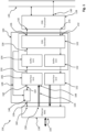
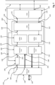
- Figure 1 schematically illustrates an example embodiment of a system 100.
- the system 100 may be a part of a communication device 156.
- the communication device 156 may be a part of a node used for communication in an IVN.
- the system 100 comprises a CAN controller 102.
- the CAN controller 102 may be configured according to the CAN standard such that the CAN controller 102 may support Classical CAN, CAN FD, and/or CAN XL.
- the CAN controller 102 comprises a transmit data output interface 126, referred to as TXD output interface 126.
- the TXD output interface 126 can be used to transmit a CAN frame 120, 122, 124 to the CAN transceiver 128.
- the CAN transceiver 128 may comprise a transmit data input interface 142, referred to as the TXD input interface 142.
- the TXD output interface 126 of the CAN controller 102 is coupled to the TXD input interface 142 of the CAN transceiver 128 via a signal connection to transmit CAN frames 120, 122, 124 from the CAN controller 102 to the CAN transceiver 128.
- the CAN transceiver 128 may be configured to generate, based on a received CAN frame 120, 122, 124, a differential voltage signal at a CAN bus interface 140 representing the received CAN frame 120, 122, 124.
- the CAN bus interface 140 of the CAN transceiver 128 may be configured to be coupled to the signal lines of the CAN bus 130, such that the differential voltage signal can be transmitted to a remote CAN transceiver (not shown) via the CAN bus 130.
- Each CAN frame 120, 122, 124 may be configured according to the CAN standard.
- each of the CAN frames 120, 122, 124 is configured as a CAN frame 120, 122, 124 according to Classical CAN, CAN FD, and/or CAN XL.
- the CAN controller 102 comprises a receive data input interface 132, also referred to as an RXD input interface 132.
- the RXD input interface 132 is for receiving a CAN frame 120, 122, 124.
- the RXD input interface 132 may be coupled to a receive data output interface 144, also referred to as an RXD output interface 144, of the CAN transceiver 128.
- the CAN transceiver 128 may detect a differential voltage signal representing a CAN frame 120, 122, 124 via the CAN bus interface 140.
- the CAN transceiver 128 may be configured to transmit a received CAN frame 120, 122, 124 to the RXD input interface 132 of the CAN controller 102 via the RXD output interface 144.
- the CAN controller 102 does not have direct access to the CAN bus 130. Rather, the CAN controller 102 may have (indirect) access to the CAN bus 130 via the CAN Transceiver 128. In particular, the CAN controller 102 may (indirectly) access the CAN bus 130 via the signal connection between the TXD output interface 126 and the TXD input interface 142, via another signal connection between the RXD output interface 144 and an RXD input interface 132, and via the CAN transceiver 128 and the associated CAN bus interface 140.
- the permission to access the CAN bus 130 to send a CAN frame 120, 122, 124 over the CAN bus 31 via a differential voltage signal is limited.
- a so-called arbitration is performed through of the CAN controller 102 and the CAN transceiver 128, the result of the arbitration being either a positive permission state, according to which the CAN controller 102 is allowed to transmit a CAN frame 120, 122, 124 on the CAN bus via the CAN transceiver 128, or a negative permission state, according to which the CAN controller 102 is not allowed to transmit a CAN frame 120, 122, 124 on the CAN bus 130 via the CAN transceiver 128.
- the CAN controller 102 performs the aforementioned arbitration until, as a result, the CAN controller 102 reaches the positive permission state for transmitting the respective CAN frame 120, 122, 124.
- the system 100 comprises a unit 106, also referred to as an interface unit 106.
- the interface unit 106 comprises a transmit data input interface 108, also referred to as a TX input interface 108.
- the interface unit 106 is configured to receive Ethernet frames 110, 114, 118 via the TX input interface 108.
- An Ethernet frame 110, 114, 118 may also be referred to as a data frame 110, 114, 118 or Ethernet data frame 110, 114, 118.
- the interface unit 106 may be configured to be coupled to an Ethernet media access control (MAC) unit 138 via the TX input interface 108.
- the MAC unit 138 may be configured in accordance with the Ethernet standard, in particular IEEE 802.3.
- the IEEE 802.3 standard refers to a collection of standards defining physical layer and data link layer media access control for wired Ethernet.
- Ethernet communications refer to the 10BASE-T1S standard as defined by IEEE 802.3cg.
- the communications are to provide for multiple communication nodes, each communication node being coupled to at least one other communication node via a common communication medium, such as a twisted pair wire, to provide for transmission of Ethernet frames 110, 114, 118 from one communication node to the other communication node.
- Each Ethernet communication node may comprise a physical layer device, wherein the device is also referred to as a phy or Ethernet transceiver.
- the Ethernet transceiver may be configured to generate a voltage signal on the communication medium representing an Ethernet packet.
- the Ethernet transceiver of a communication node may be coupled to a control unit configured to control access to the communication medium.
- the control unit may also be referred to as the MAC unit 138.
- the MAC unit 138 may also be referred to as a MAC controller 138 or a transmitter.
- the MAC unit 138 may be configured to access the communication medium via the Ethernet transceiver.
- the MAC unit 138 may be configured to react on signals (CRS, COL not shown here) from the interface units 106, 152 to obtain positive permission to access or negative permission (deny access) with respect to the communication medium.
- Two communication nodes each comprising an Ethernet transceiver and a MAC unit 138, may be coupled via a communication medium such that the communication medium extends from the Ethernet transceiver of one communication node to the Ethernet transceiver of the other communication node.
- One of the transceivers may generate a voltage signal that is transmitted over the communication medium to the other transceiver, wherein the voltage signal represents an Ethernet packet.
- the transmission over the communication medium extending from an Ethernet transceiver to another Ethernet transceiver may be referred to and/or configured as a media dependent transmission.
- the Ethernet MAC 138 may comprise a transmit data output interface 158, which may also be referred to as a TX output interface 158.
- a signal connection 154 may extend from the TX output interface 158 to the TX input interface 108 of the interface unit 106.
- the Ethernet MAC 138 may be configured to transmit an Ethernet frame 110, 114, 118 from the TX output interface 158 to the TX input interface 108 of the interface unit 106 via the signal connection 154.
- the transmission of the Ethernet frame 110, 114, 118 to the TX input interface 108 may be performed serially. As an effect, the transmission on this interface of the Ethernet frame 110, 114, 118 may be independent of the communication medium over which the Ethernet frame 110, 114, 118 is to be transmitted by the Ethernet transceiver.
- the interface unit 106 may also be independent of the communication mode used to transmit the Ethernet frame 110, 114, 118 over the communication medium. As a result, the interface unit 106 may also be configured as a media independent interface unit 106. In an example, the interface unit 106 may be part of and/or referred to as a MII interface unit 106. However, the interface unit 106 may also be part of and/or refer to other subtypes of a media-independent interface, such as reduced media-independent interface (RMII), gigabit media-independent interface (GMII), reduced gigabit media-independent interface (RGMII), 10-gigabit media-independent interface (XGMII), or serial gigabit media-independent interface (SGMII).
- RMII reduced media-independent interface
- GMII gigabit media-independent interface
- RGMII reduced gigabit media-independent interface
- XGMII 10-gigabit media-independent interface
- SGMII serial gigabit media-independent interface
- the system 100 further comprises a buffer unit 104.
- the buffer unit 104 may also refer to as a buffer 104.
- the interface unit 106 is preferably coupled to the buffer unit 104 via a signal connection 150.
- the interface unit 106 may transmit an Ethernet frame 110, 114, 118 previously received by the interface unit 106 via the TX input interface 108 to the buffer unit 104.
- the signal connection 150 may be used for the transmission.
- the buffer unit 104 is configured to store at least one Ethernet frame 110, 114, 118.
- the buffer unit 104 may comprise a predefined, limited capacity for storing data, in particular data of one or more Ethernet frames 110, 114, 118.
- the capacity for storing data may also be referred to as a reference capacity.
- the Ethernet frames 110, 114, 118 are preferably configured according to the IEEE 802.3 standard.
- Each Ethernet frame 110, 114, 118 may comprise multiple fields.
- each Ethernet frame 110, 114, 118 comprises a preamble field and a start of frame field, referred to as an SFD field.
- the preamble field and the SFD field may have a combined data size of 8 bytes.
- Each Ethernet frame 110, 114, 118 may further comprise an Ethernet Frame field comprising at least a destination address field, a source address field, a type field, a payload field, and a check field also referred to as a frame check sequence.
- the destination address may comprise 6 bytes, the source address 6 bytes, the type field 2 bytes, the payload field between 46 and 1500 bytes, and the check field 4 bytes of data.
- Each Ethernet frame 110, 114, 118 may have a minimum size of 64 bytes and/or a maximum size of 1518 bytes.
- the buffer unit 104 may be configured such that the reference capacity of the buffer unit 104 is configured to store a predefined number of at least one Ethernet frame 110, 114, 118 in accordance with the Ethernet standard, such as IEEE 802.3.
- the reference capacity may be limited to the data of the predefined number of at least on Ethernet frame 110, 114, 118.
- the buffer unit 104 comprises a reference capacity configured to store a predefined number of Ethernet frames 110, 114, 118 each having a maximum data size.
- the number of Ethernet frames 110, 114, 118 may be, for example, one, two, three, or another natural number.
- the number of Ethernet frames 110, 114, 118 is either one or two.
- the small number of Ethernet frames 110, 114, 118 that can at maximum be stored by the buffer unit 104 offers the advantage that the buffer unit 104 can be configured to be particularly compact in size. This compact design of the buffer unit 104 is particularly advantageous if the buffer unit 104 comprises the same structural size as the CAN transceiver 128.
- the buffer unit 104 is also coupled to the CAN controller 102.
- the buffer unit 104 may be coupled to the CAN controller 102 via the signal connection 134.
- the buffer unit 104 is configured to transmit an Ethernet frame 110, 114, 118 stored by the buffer unit 104 to the CAN controller 102.
- An Ethernet frame 110, 114, 118 stored by the buffer unit 104 may also be referred to as a buffered Ethernet frame 110, 114, 118. Transferring an Ethernet frame 110, 114, 118 from the buffer unit 104 to the CAN controller 102 may free up the corresponding storage space of the buffer unit 104.
- the CAN controller 102 may be configured to read out an Ethernet frame 110, 114, 118 from the buffer unit 104 via the signal connection 134 such that the read out results in the transfer of the Ethernet frame 110, 114, 118 to the CAN controller 102.
- the CAN controller 102 is configured to generate a CAN frame 120, 122, 124 based on a received Ethernet frame 110, 114, 118.
- the CAN frame 120, 122, 124 corresponds to a CAN frame according to the CAN standard, like Classical CAN, CAN FD or CAN XL.
- the CAN frame may comprise and/or be formed from at least (by) a start of frame (SOF) field, an arbitration field, a control field, a payload field, a CRC field, an acknowledgement (ACK) field, and an end of frame (EOF) field.
- SOF start of frame
- ACK acknowledgement
- EEF end of frame
- the CAN controller 102 may be configured to generate a CAN frame 120, 122, 124 based on the received Ethernet frame 110, 114, 118 such that the payload field of the CAN frame 120, 122, 124 comprises, in particular encompasses, the complete Ethernet frame 110, 114, 118 or only a part of the Ethernet frame 110, 114, 118, for example such as only the payload field of the Ethernet frame 110, 114, 118.
- the payload field of the CAN frame 120, 122, 124 comprises the complete Ethernet frame 110, 114, 118
- the resulting type of communication may also be referred to as a tunneling of the Ethernet frame 110, 114, 118 via a CAN communication and/or via CAN frames 120, 122, 124.
- the CAN controller 102 comprises the TXD output interface 126 for sending a CAN frame 120, 122, 124 via the CAN transceiver 128 such that the CAN transceiver 128 generates a differential voltage signal on the CAN bus 130 representing the CAN frame 120, 122, 124 to be transmitted.
- the CAN controller 102 is configured to perform what is referred to as arbitration, wherein the result of the arbitration indicates whether the CAN controller 102 is positively allowed to indirectly access the CAN bus 130 to transmit the CAN frame 120, 122, 124 or whether the corresponding access is denied.
- Access to the CAN bus 130 may be denied if other CAN nodes are already transmitting a CAN frame on the CAN bus 130 or if other CAN nodes have a higher priority to transmit a CAN frame on the CAN bus 130. Therefore, it may take a certain amount of time, also referred to as a waiting time, for the CAN controller 102 to receive a positive permission through arbitration to access the CAN bus 130 via the CAN transceiver 128 to transmit the CAN frame 120, 122, 124.
- the permission state may be either positive (thus a positive permission state A1) or negative (thus a negative permission state A2).
- the CAN controller 102 is permitted to access the CAN bus 130 via the CAN transceiver 128.
- the CAN controller 102 is not permitted (and/or denied) to access the CAN bus 130 via the CAN transceiver 128.
- the permission state relates to the positive/negative permission to transfer a complete CAN frame 120, 122, 124 over the CAN bus 130.
- the permission state may not relate to the permission to attend to an arbitration.
- the result of the arbitration is either the positive permission state A1 or the negative permission state A2.
- the negative permission state A2 exists between the time T0 and time T10, so that the CAN controller 102 is not allowed to access the CAN bus 130 via the CAN transceiver 128 during the time period T0 to T10. From time T10 the permission to access the CAN bus is allowed.
- the MAC unit 138 may be configured to transmit a first Ethernet frame 110 to the interface unit 106 in the time period from time T1 to time T2. From the interface unit 106, the first Ethernet frame 110 may be transmitted to the buffer unit 104, wherein the buffer unit 104 stores the first Ethernet frame 110.
- the MAC unit 138 comprises a control interface 160. Via the control interface 160, the MAC unit 138 may receive a signal referred to as a TX reference rate signal.
- the TX reference rate signal may be and/or represent a transmission rate, also referred to as a reference transmission rate, at which the MAC unit 138 has to transmit data of an Ethernet frame 110, 114, 118 from the TX output interface 158 to the TX input interface 108 of the interface unit 106 via the signal connection 154.
- the MAC unit 138 may therefore be configured to adjust the transmission rate of the data of an Ethernet frame 110, 114, 118 at the TX output interface 158 based on the TX reference rate signal so that the transmission rate (of the data of the Ethernet frames 110, 114, 118) matches the reference transmission rate.
- the system 100 is configured to generate the TX reference rate signal.
- the system 100 further comprises the interface 136, referred to as the TX rate interface 136.
- the system 100 is configured to transmit the TX reference rate signal via the TX rate interface 136.
- the TX rate interface 136 is coupled to the control interface 160 of the MAC unit 138 via a signal connection such that the system 100 can transmit the TX reference rate signal to the control interface 160 of the MAC unit 138.
- the TX reference rate signal may be used by the system 100 to control the rate of transmission of data from the Ethernet frames 110, 114, 118 to the TX input interface 108.
- the buffer unit 104 may comprise the same structure size as the CAN transceiver 128, so that the buffer unit 104 and the CAN transceiver 128 and the CAN controller 102 may be integrated into the same integrated circuit, IC. Because of this relationship, in an example, the capacity of the buffer unit 104 to store Ethernet frames 110, 114, 118 may be limited. In an example, the buffer unit 104 may be configured to store a maximum of two Ethernet frames 110, 114, 118.
- the permission state of the CAN controller 102 between time T0 and time T5 is a negative permission state A2, such that the CAN controller 102 does not have positive permission to access the CAN bus 130 via the CAN transceiver 128.
- the first Ethernet frame 110 which is transmitted to the buffer unit 104 via the interface unit 106 and stored by the buffer unit 104 in the time period T1 to T2, can therefore not be transferred to and/or retrieved by the CAN controller 102 in the time period T0 to T10.
- the first Ethernet frame 110 must therefore remain stored in the buffer unit 104.
- each Ethernet frame 110, 114, 118 is followed by a so-called gap 112, 116 which is also referred to as inter-frame gap 112, 116 or inter-packet gap 112, 116.
- gap 112, 116 no transmission of data of an Ethernet frame 110, 114, 118 takes place.
- a first gap 112 is performed directly after the transmission of the first Ethernet frame 110 and the transmission of the second Ethernet frame 114 is performed directly after the first gap 112.
- the transmission of the second Ethernet frame 114 may be followed directly by a second gap 116.
- the buffer unit 104 comprises a reference capacity for storing only two Ethernet frames 110, 114. With the transmission of the first Ethernet frame 110 to the interface unit 106 and the subsequent transmission of the first Ethernet frame 110 from the interface unit 106 to the buffer unit 104, a corresponding portion of the reference capacity of the buffer unit 104 is occupied by the data of the first Ethernet frame 110.
- the portion of the reference capacity of the buffer unit 104 occupied by data from at least one Ethernet frame 110, 114, 118 may be referred to in an example as the fill level of the buffer unit 104.
- the remaining portion of the reference capacity of the buffer unit 104 that is not occupied by data from at least one Ethernet frame 110, 114, 118 may be referred to as the remaining capacity of the buffer unit 104 or the free capacity of the buffer unit 104.
- a threshold fill level may be predefined and/or stored by the CAN controller 102.
- the threshold fill level of the buffer unit 104 may correspond to a (theoretical and/or predefined) fill level of the buffer unit 104 with (theoretically) stored data at which the remaining free portion of the reference capacity, in particular the remaining capacity, is less than the amount of data of a single Ethernet frame according to the IEEE 802.3 standard.
- the threshold fill level of the buffer unit 104 may correspond to the (theoretical and/or predefined) fill level of the buffer unit 104 with (theoretical) stored data at which the remaining free portion of the reference capacity is configured to store a predefined portion of the data of a single Ethernet frame according to the IEEE 802.3 standard, such as the IEEE 802.3cg standard.
- the predefined portion may be between 1% and 99%, in particular between 10% and 80%.
- FIG 6 an example of a course of the fill level of the buffer unit 104 is schematically shown. From time T1 on, the fill level of the buffer unit 104 increases. The increase of the fill level of the buffer unit is caused by the transmission of the first Ethernet frame 110 while the CAN controller 102 has a negative permission state A2. During the period T2 to T3, the fill level of the buffer unit 104 remains at the same level. The first gap 112 is followed directly by the transmission of the second Ethernet frame 114, so that the fill level of the buffer unit 104 continues to increase from time T3 on. At the time T 11, the fill level of the buffer unit 104 reaches the predefined threshold fill level F2.
- the threshold fill level F2 By reaching the threshold fill level F2, it is clear in an example that the remaining capacity of the buffer unit 104 is so small, that no further complete Ethernet frame 118 shall be received by the interface unit 106 until the fill level of the buffer unit 104 drops below the threshold fill level F2 again. Just the second Ethernet frame 114 may be continued to be transmitted to the interface unit 106 and indirectly to the buffer unit 104.
- the system 100 is configured to generate the TX reference rate signal representing the reference transmission rate of data of an Ethernet frame 110, 114, 118 to the TX input interface 108.
- the system 100 is configured to generate the TX reference rate signal depending on the fill level of the buffer unit 104 and/or a permission state of the CAN controller 102.
- the reference transmission rate may also be referred to as the TX transmission rate.
- the TX transmission rate is the rate at which the data of an Ethernet frame 110, 114, 118 is to be transmitted to the TX input interface 108. If the fill level of the buffer unit 104 is low and/or less than the threshold fill level F2, the TX transmission rate may be high, in particular a predefined maximum transmission rate. If the fill level of the buffer unit 104 reaches and/or is greater than the threshold fill level F2, it may be necessary for the TX transmission rate to be or become small, in particular to become zero at the next gap 112, 116.
- the CAN controller 102 may be coupled to the buffer unit 104 such that the CAN controller 102 can detect the fill level of the buffer unit 104.
- the system 100 and/or the CAN controller 102 may be configured to set the TX transmission rate to a first predefined transmission rate R1 if the detected fill level of the buffer unit 104 is less than the threshold fill level.
- the first predefined transmission rate R1 may also be referred to as the first transmission rate R1.
- the first transmission rate R1 is a predefined maximum allowable transmission rate for transmitting data of an Ethernet frame 110, 114, 118 to the TX input interface 108.
- the first transmission rate R1 may be 10 Mbits, 25 Mbits, or 100 Mbits.
- the system 100 and/or the CAN controller 102 may be configured to set the TX transmission rate to a second predefined transmission rate R2 if the detected level of the buffer unit 104 reaches or exceeds the threshold fill level.
- the second predefined transmission rate R2 may also be referred to as the second transmission rate R2.
- the second transmission rate R2 is less than the first transmission rate R1.
- the second transmission rate R2 may be zero.
- the second transmission rate R2 may be less than 70%, less than 50%, less than 30%, or less than 10% of the first transmission rate R1.
- the CAN controller 102 may be coupled to the buffer unit 104 such that the CAN controller 102 can detect the fill level of the buffer unit 104. Further, the CAN controller 102 may be coupled to the buffer unit 104 such that the CAN controller 102 can detect the time of transmission of data of an Ethernet frame 114 from the interface unit 106 to the buffer unit 104. In an example, based on the detected data of the Ethernet frame 114 from the interface unit 106 to the buffer unit 104, the CAN controller 102 may be configured to detect a start time T3 at which the transmission of data of an Ethernet frame 114 to the interface unit 106 begins and/or an end time T4 at which the transmission of data of the Ethernet frame 114 to the interface unit 106 ends. The CAN controller 102 may be configured to determine, based on the start time T3 and/or the end time T4, a gap 116 that directly follows to the end time T4 of the transmission of the Ethernet frame 114 to the interface unit 106.
- the CAN controller 102 may be (indirectly) coupled to the interface unit 106 via the buffer unit 104 such that the CAN controller 102 can detect the time of transmission of the data of an Ethernet frame 114 to the TX input interface 108 of the interface unit 106.
- the CAN controller 102 may be (indirectly) coupled to the interface unit 106 via the buffer unit 104 such that the CAN controller 102 can detect the start time T3 of an Ethernet frame 114, the end time T4 of an Ethernet frame, and/or the gap 116.
- the CAN controller 102 may be configured to determine the time period T4 to T5 of the gap 116 based on the detected end time T4.
- the CAN controller 102 may be configured to set the TX transmission rate to the second transmission rate R2 only at a time T6 during a gap 116 if the fill level of the buffer unit 104 has previously reached or exceeded the threshold fill level. In an example, the CAN controller 102 may be configured to determine the gap 116 following the Ethernet frame 114 transmitted to the TX input interface 108 during which transmission the fill level of the buffer unit 104 reached the threshold fill level F2. In an example, the CAN controller 102 may detect the time T11 at which the fill level of the buffer unit 104 reaches the threshold fill level F2.
- the CAN controller 102 may detect the end time T4 of the Ethernet frame 114 which data is transmitted to the TX input interface 108 during a transmission period T3 to T4, wherein the time T11 at which the fill level of the buffer unit 104 reached the threshold fill level F2 falls within the transmission period T3 to T4.
- the CAN controller 102 may be configured to detect the next possible gap 116 following in time T11. Further, the CAN controller 102 may be configured to set the TX transmission rate to the second transmission rate R2 at a time T6, where the time period T6 is during the detected gap 116.
- the CAN controller 102 may first wait to reach time T6 in the next gap 116 and set the TX transmission rate to the second transmission rate R2 at the time T6 in the gap 116.
- the TX transmission rate may not be reduced directly at the time T1, when the fill level of the buffer unit 104 reaches the threshold fill level, but only afterward at time T6. This prevents the TX transmission rate from changing, in particular from being set to zero, during an active transmission of data of an Ethernet frame 114. As a technical effect, this prevents data of an Ethernet frame 114 from being lost.
- data of a (further) Ethernet frame 118 can be prevented from being transmitted to the interface unit 106 while the remaining capacity of the buffer unit 104 is no longer sufficient to store the data of the (further) Ethernet frame 118.
- the remaining capacity decreases between time T6 and time T7, so that the fill level of the buffer unit 104 reaches at time T7 the threshold fill level F2, and even decreases further afterwards.
- the CAN controller 102 may be configured to detect if the fill level is less than the threshold fill level F2.
- the CAN controller 102 may be configured to set the TX transmission rate back to the first transmission rate R1, if the CAN controller 102 detects that the fill level of the buffer unit 104 is less than the threshold fill level F2.
- the change from the second transmission rate R2 to the first transmission rate R1 is shown schematically in Figure 3 at time T7.
- the system 100 and/or the CAN controller 102 is configured to set the TX transmission rate to the first transmission rate R1 if both of the following conditions are met: (1) the fill level of the buffer unit 104 is less than the threshold fill level; and (2) the CAN controller 102 is in a positive permission state.
- the system 100 and/or the CAN controller is configured to set the TX transmission rate to the second transmission rate R2 if at least one of the following two conditions is met: (1a) the buffer unit fill level has reached or exceeded the threshold fill level; (2a) the CAN controller 102 is in a negative permission state.
- the CAN controller 102 may be configured to set the TX transmission rate to the second transmission rate R2 only at a time T6 during a gap 116 after at least one of the following two conditions is met: (1a) the buffer unit fill level has reached or exceeded the threshold fill level; (2a) the CAN controller 102 is in a negative permission state.
- condition (1a) reference is made to the preceding explanations in an analogous manner.
- the CAN controller 102 may be configured to determine the gap 116 directly following the Ethernet frame 114 transmitted to the TX input interface 108 during the transmission of which at least one of the two conditions (1a), (2a) is met.
- the CAN controller may determine the time at which the negative permission condition occurs.
- the negative permission state may occur if the CAN controller 102 has lost an arbitration. In another example, the negative permission state may occur if the CAN controller does not have and/or lost permission to access the CAN bus 130 via the CAN transceiver 128 due to a traffic shaping policy. Other examples of denying the CAN controller 102 to access the CAN bus 130 via the CAN transceiver 128 can be derived from the standards for Classical CAN, CAN FD, and/or CAN XL.
- the TX reference rate signal is a clock signal.
- the TX reference rate signal may be and/or represent a clock frequency or the clock rate at which data is to be transmitted to the TX input interface 108.
- the TX reference rate signal is transmitted from the system 100 via the TX rate interface 136 to the control interface 160 of the MAC unit 138, which, based on the clock frequency or the clock rate, adjusts the transmission rate of the data from the TX output interface 158 to the TX input interface 108 of the interface unit 106 so that the transmission rate corresponds to the clock frequency or the clock rate.
- the clock rate and/or the clock frequency may be reduced. It is possible to continuously decrease the clock rate and/or clock frequency. However, it had been found advantageous if the second transmission rate R2 is zero, so that in this case the clock frequency and/or clock rate are also zero.
- the transition from the first transmission rate R1 to the second transmission rate R2, if any of the aforementioned conditions are met, is preferably performed during the gap 116, in particular at time T6.
- each Ethernet frame 110, 114, 118 transmitted from the MAC unit 138 to the TX input interface 108 of the interface unit 106 is an Ethernet frame 110, 114, 118.
- the system 100 may be configured to generate and transmit a CAN frame 120, 122, 124 based on an Ethernet frame 110, 114, 118 over the CAN bus 130.
- Figure 4 schematically illustrates an example of the course of the CAN frames 120, 122, 124 to be transmitted.
- the interface unit 106 may be configured to receive data of an Ethernet frame 110, 114, 118 serially at the TX input interface 108.
- the data may be transmitted bit by bit.
- the MAC unit 138 may be configured to serially transmit the data of an Ethernet frame 110, 114, 118 from TX output interface 158 to TX input interface 108.
- the interface unit 106 and/or the buffer unit 104 may be configured to transmit a complete Ethernet frame 110, 114, 118, in particular as a bundle, from the interface unit 106 to the buffer unit 104.
- the data of an Ethernet frame 110, 114, 118 may be transmitted in parallel from the interface unit 106 to the buffer unit 104.
- the data of an Ethernet frame 110, 114, 118 may be transmitted non-serially from the interface unit 106 to the buffer unit 104 in an example.
- Figure 7 schematically illustrates another embodiment of the system 100.
- system 100 of Figure 7 reference is made to the preceding explanations, preferred features, technical effects and advantages in an analogous manner as explained for the system 100 in connection with Figures 1-6 .
- the system 100 may further comprise, in an example, the CAN transceiver 128.
- the CAN transceiver 128 comprises a CAN bus interface 140.
- the CAN bus interface 140 may comprise two terminals.
- the CAN transceiver 128 may be configured to generate a differential voltage signal at the CAN bus interface 140, in particular between the two terminals of the CAN bus interface 140, the differential voltage signal may represent a CAN frame 120, 122, 124. Using the differential voltage signal, the CAN frame 120, 122, 124 can be transmitted to another node (not shown) via the CAN bus 130.
- the CAN transceiver 128 may comprise a TXD input interface 142 coupled to the TXD output interface 126 of the CAN controller 102.
- the CAN transceiver 128 may also comprise an RXD output interface 144 coupled to the TXD input interface 132 of the CAN controller 102.
- the CAN transceiver 128, the CAN controller 102, and the buffer unit 104 are integrated into a single integrated circuit, IC.
- the integration of the CAN transceiver 128 in the same IC in which the CAN controller 102 and the buffer unit 104 are integrated offers the advantage that the system 100 is particularly compact in size.
- the structure size of the integrated circuit in this case may be determined by the structure size of the CAN transceiver 128.
- the reference capacity of the buffer unit 104 may be limited such that the buffer unit 104 can store a maximum of three Ethernet frames 110, 114, 118, a maximum of two Ethernet frames 110, 114, 118, or a maximum of only one Ethernet frame 110, 114, 118.
- the interface unit 106 may further be integrated into the integrated circuit that also integrates the CAN transceiver 128, the CAN controller 102, and the buffer unit 104.
- the interface unit 106 may not be able to detect the level of the buffer unit 104.
- the interface unit 106 may comprise a (further) interface 162, referred to as the base interface 162.
- the interface unit 106 is configured to generate a signal referred to as a TX base rate signal.
- the TX base rate signal may be predefined and/or represent a maximum allowable transmission rate for transmitting data to the TX input interface 108.
- the maximum allowable transmission rate for the TX input interface 108 may also be referred to as the transmission control rate.
- the interface unit 106 is configured to generate the TX base rate signal independent of a fill level of the buffer unit 104 and/or independent of a permission state of the CAN controller 102.
- the system 100 comprises another unit 146 referred to as a rate control unit 146.
- the rate control unit 146 may be coupled to the interface unit 106.
- the rate control unit 146 may be integrated into a signal connection 164 extending from the base interface 162 to the TX rate interface 136.
- the base rate signal is transmitted to the rate control unit 146.
- the rate control unit 146 is configured to generate and transmit the TX reference rate signal to the TX rate interface 136.
- the TX reference rate signal generated by the rate control unit 146 may be transmitted to the control interface 160 of the MAC unit 138 via the TX rate interface 136.
- the rate control unit 146 is configured to generate the TX reference rate signal from the TX base rate signal depending on a fill level of the buffer unit 104 and/or depending on a permission state of the CAN controller 102.
- the rate control unit 146 may be configured as a controllable switch, such as a controllable MOS FET.
- the CAN controller 102 may control the rate control unit 146 via the signal connection 148 (extending from the CAN controller 102 to the rate control unit 146) such that the rate control unit 146 disconnects the signal connection 164, in particular via the switchable switch.
- a TX reference rate signal having a clock frequency and/or a clock rate of zero is thereupon present at the TX rate interface 136. Due to such a TX reference rate signal, the MAC unit 138 will not transmit further data of an Ethernet frame from the TX output interface 158 to the TX input interface 108. In other words, by interrupting the signal connection 164 in an example, the second predefined transmission rate R2 may be achieved.
- the rate control unit 146 is configured to transmit the corresponding TX reference rate signal through the TX rate unit146, for example to set the TX reference rate to the first transmission rate R1.
- the CAN controller 102 may control the rate control unit 146 via the signal connection 148 such that the rate control unit 146 restores the signal connection 164, in particular via the switchable switch.
- closing the switchable switch may restore the TX transmission rate to the first, predefined transmission rate R1, which preferably corresponds to the maximum, allowable transmission rate and/or the maximum transmission control rate.
- the first, predefined transmission rate R1 may be represented by the base rate signal.
- the TX reference rate signal corresponding to the base rate signal is transmitted to the control interface 160 of the MAC unit 138.
- the MAC unit 138 will then resume transmitting Ethernet frames 110, 114, 118 from the TX output interface 158 to the TX input interface 108.
- the interface unit 106 may be not configured to detect the level of the buffer unit 104.
- the CAN controller 102 is configured may be configured to detect the level of the buffer unit 104.
- the CAN controller 102 may further be configured to control the rate control unit 146.
- the system 100 may be used to temporarily prevent further Ethernet frames from being transmitted from a MAC unit 138 to the interface unit 106, in case the free capacity of the buffer unit 104 is too low.
- the geometric size of the system 100 may be kept compact while effectively preventing Ethernet frames 110, 114, 118 from being lost.
- Figure 8 schematically illustrates one embodiment for a method for the system 100.
- the method may comprise the steps of:
- the systems and methods described herein may at least partially be embodied by a computer program or a plurality of computer programs, which may exist in a variety of forms both active and inactive in a single computer system or across multiple computer systems.
- they may exist as software program(s) comprised of program instructions in source code, object code, executable code or other formats for performing some of the steps.
- Any of the above may be embodied on a computer-readable medium, which may include storage devices and signals, in compressed or uncompressed form.
- the term "computer” refers to any electronic device comprising a processor, such as a general-purpose central processing unit (CPU), a specific-purpose processor or a microcontroller.
- a computer is capable of receiving data (an input), of performing a sequence of predetermined operations thereupon, and of producing thereby a result in the form of information or signals (an output).
- the term "computer” will mean either a processor in particular or more generally a processor in association with an assemblage of interrelated elements contained within a single case or housing.
- processor or “processing unit” refers to a data processing circuit that may be a microprocessor, a co-processor, a microcontroller, a microcomputer, a central processing unit, a field programmable gate array (FPGA), a programmable logic circuit, and/or any circuit that manipulates signals (analog or digital) based on operational instructions that are stored in a memory.
- memory refers to a storage circuit or multiple storage circuits such as read-only memory, random access memory, volatile memory, non-volatile memory, static memory, dynamic memory, Flash memory, cache memory, and/or any circuit that stores digital information.
- a "computer-readable medium” or “storage medium” may be any means that can contain, store, communicate, propagate, or transport a computer program for use by or in connection with the instruction execution system, apparatus, or device.
- the computer-readable medium may be, for example but not limited to, an electronic, magnetic, optical, electromagnetic, infrared, or semiconductor system, apparatus, device, or propagation medium.
- the computer-readable medium may include the following: an electrical connection having one or more wires, a portable computer diskette, a random-access memory (RAM), a read-only memory (ROM), an erasable programmable read-only memory (EPROM or Flash memory), an optical fiber, a portable compact disc read-only memory (CDROM), a digital versatile disc (DVD), a Blu-ray disc (BD), and a memory card.
- RAM random-access memory
- ROM read-only memory
- EPROM or Flash memory erasable programmable read-only memory
- CDROM compact disc read-only memory
- DVD digital versatile disc
- BD Blu-ray disc
Landscapes
- Engineering & Computer Science (AREA)
- Computer Networks & Wireless Communication (AREA)
- Signal Processing (AREA)
- Quality & Reliability (AREA)
- Small-Scale Networks (AREA)
Priority Applications (3)
| Application Number | Priority Date | Filing Date | Title |
|---|---|---|---|
| EP23184546.2A EP4492736A1 (de) | 2023-07-10 | 2023-07-10 | Kommunikationssystem und verfahren |
| CN202410722451.XA CN119299250A (zh) | 2023-07-10 | 2024-06-05 | 通信系统和方法 |
| US18/766,391 US20250023754A1 (en) | 2023-07-10 | 2024-07-08 | Communication system and method |
Applications Claiming Priority (1)
| Application Number | Priority Date | Filing Date | Title |
|---|---|---|---|
| EP23184546.2A EP4492736A1 (de) | 2023-07-10 | 2023-07-10 | Kommunikationssystem und verfahren |
Publications (1)
| Publication Number | Publication Date |
|---|---|
| EP4492736A1 true EP4492736A1 (de) | 2025-01-15 |
Family
ID=87245449
Family Applications (1)
| Application Number | Title | Priority Date | Filing Date |
|---|---|---|---|
| EP23184546.2A Pending EP4492736A1 (de) | 2023-07-10 | 2023-07-10 | Kommunikationssystem und verfahren |
Country Status (3)
| Country | Link |
|---|---|
| US (1) | US20250023754A1 (de) |
| EP (1) | EP4492736A1 (de) |
| CN (1) | CN119299250A (de) |
Families Citing this family (1)
| Publication number | Priority date | Publication date | Assignee | Title |
|---|---|---|---|---|
| LU500592B1 (de) * | 2021-08-30 | 2023-02-28 | Phoenix Contact Gmbh & Co | Netzwerk-Kopplungseinrichtung für ein Netzwerk und Netzwerk mit einer Netzwerk- Kopplungseinrichtung |
Citations (3)
| Publication number | Priority date | Publication date | Assignee | Title |
|---|---|---|---|---|
| EP1416762A2 (de) * | 1998-12-02 | 2004-05-06 | Nortel Networks Limited | Flusskontrolle von rahmenbasierten Daten in einem synchronen, digitalen Netz |
| CN111245743A (zh) * | 2020-01-09 | 2020-06-05 | 浙江吉利汽车研究院有限公司 | 一种信息处理方法、存储介质、网关及汽车 |
| CN111464409A (zh) * | 2020-03-25 | 2020-07-28 | 浙江中控研究院有限公司 | 一种can总线并入时间敏感网络的数据交换装置及网络 |
-
2023
- 2023-07-10 EP EP23184546.2A patent/EP4492736A1/de active Pending
-
2024
- 2024-06-05 CN CN202410722451.XA patent/CN119299250A/zh active Pending
- 2024-07-08 US US18/766,391 patent/US20250023754A1/en active Pending
Patent Citations (3)
| Publication number | Priority date | Publication date | Assignee | Title |
|---|---|---|---|---|
| EP1416762A2 (de) * | 1998-12-02 | 2004-05-06 | Nortel Networks Limited | Flusskontrolle von rahmenbasierten Daten in einem synchronen, digitalen Netz |
| CN111245743A (zh) * | 2020-01-09 | 2020-06-05 | 浙江吉利汽车研究院有限公司 | 一种信息处理方法、存储介质、网关及汽车 |
| CN111464409A (zh) * | 2020-03-25 | 2020-07-28 | 浙江中控研究院有限公司 | 一种can总线并入时间敏感网络的数据交换装置及网络 |
Non-Patent Citations (1)
| Title |
|---|
| RAHMANI M ET AL: "Traffic Shaping for Resource-Efficient In-Vehicle Communication", IEEE TRANSACTIONS ON INDUSTRIAL INFORMATICS, IEEE SERVICE CENTER, NEW YORK, NY, US, vol. 5, no. 4, 1 November 2009 (2009-11-01), pages 414 - 428, XP011334275, ISSN: 1551-3203, DOI: 10.1109/TII.2009.2019127 * |
Also Published As
| Publication number | Publication date |
|---|---|
| US20250023754A1 (en) | 2025-01-16 |
| CN119299250A (zh) | 2025-01-10 |
Similar Documents
| Publication | Publication Date | Title |
|---|---|---|
| US10693905B2 (en) | Invalidity detection electronic control unit, in-vehicle network system, and communication method | |
| US11256498B2 (en) | Node, a vehicle, an integrated circuit and method for updating at least one rule in a controller area network | |
| US11272543B2 (en) | Physical layer device that connects to a shared media and method for operating a physical layer device that connects to a shared media | |
| US20200007567A1 (en) | Method for preventing electronic control unit from executing process based on malicious frame transmitted to bus | |
| US11295036B2 (en) | Method of using protocol CRC to implement end to end protection of a CAN message | |
| CN107817779B (zh) | 基于以太网交换机的信息验证未注册的装置的系统及方法 | |
| US20200021611A1 (en) | Fraud detection method, fraud detection device, and recording medium | |
| CN105388858B (zh) | 网络中通信节点的操作方法 | |
| US10554545B2 (en) | Data transmission in a communications network | |
| US20100158045A1 (en) | Method for transmitting/receiving data frame in can protocol | |
| US20240031199A1 (en) | Anomaly determination method, anomaly determination device, and recording medium | |
| CN110784385B (zh) | 用于在多主机总线上传送数据帧的方法和装置 | |
| US20230353417A1 (en) | Can module, can transceiver, can system and method for can module | |
| US12314203B2 (en) | Can controller, can device and method for the can controller | |
| US12432087B2 (en) | Delay module for a controller area network (CAN), a CAN device, and a method for the delay module | |
| US20250023754A1 (en) | Communication system and method | |
| US10230656B2 (en) | Method and apparatus for controlling message over heterogeneous network | |
| US11337184B2 (en) | Method and apparatus for transmitting and receiving data stream performed in vehicle network | |
| EP4387176A1 (de) | Can-vorrichtung und verfahren für die can-vorrichtung | |
| US20250300941A1 (en) | Can device, can system and method for the can device | |
| EP4304136A1 (de) | Steuerungsbereichsnetzvorrichtungen und verfahren | |
| US20260089026A1 (en) | Coordinator ethernet node, communication system, and method | |
| EP4304135B1 (de) | Steuergerätenetzsendeempfänger, steuergerätenetzknoten, steuergerätenetzsystem und verfahren für den steuergerätenetzsendeempfänger | |
| US11671455B2 (en) | Ethernet communications device and method for operating an ethernet communications device | |
| EP4718785A1 (de) | Übertragung von ethernet-rahmen mit priorität |
Legal Events
| Date | Code | Title | Description |
|---|---|---|---|
| PUAI | Public reference made under article 153(3) epc to a published international application that has entered the european phase |
Free format text: ORIGINAL CODE: 0009012 |
|
| STAA | Information on the status of an ep patent application or granted ep patent |
Free format text: STATUS: THE APPLICATION HAS BEEN PUBLISHED |
|
| AK | Designated contracting states |
Kind code of ref document: A1 Designated state(s): AL AT BE BG CH CY CZ DE DK EE ES FI FR GB GR HR HU IE IS IT LI LT LU LV MC ME MK MT NL NO PL PT RO RS SE SI SK SM TR |
|
| STAA | Information on the status of an ep patent application or granted ep patent |
Free format text: STATUS: REQUEST FOR EXAMINATION WAS MADE |
|
| 17P | Request for examination filed |
Effective date: 20250715 |
|
| STAA | Information on the status of an ep patent application or granted ep patent |
Free format text: STATUS: EXAMINATION IS IN PROGRESS |