EP4492821A1 - Haut-parleur et dispositif électronique - Google Patents
Haut-parleur et dispositif électronique Download PDFInfo
- Publication number
- EP4492821A1 EP4492821A1 EP23849491.8A EP23849491A EP4492821A1 EP 4492821 A1 EP4492821 A1 EP 4492821A1 EP 23849491 A EP23849491 A EP 23849491A EP 4492821 A1 EP4492821 A1 EP 4492821A1
- Authority
- EP
- European Patent Office
- Prior art keywords
- speaker
- yoke
- disposed
- voice coil
- magnetic circuit
- Prior art date
- Legal status (The legal status is an assumption and is not a legal conclusion. Google has not performed a legal analysis and makes no representation as to the accuracy of the status listed.)
- Pending
Links
Images

Classifications
-
- H—ELECTRICITY
- H04—ELECTRIC COMMUNICATION TECHNIQUE
- H04R—LOUDSPEAKERS, MICROPHONES, GRAMOPHONE PICK-UPS OR LIKE ACOUSTIC ELECTROMECHANICAL TRANSDUCERS; ELECTRIC HEARING AIDS; PUBLIC ADDRESS SYSTEMS
- H04R9/00—Transducers of moving-coil, moving-strip, or moving-wire type
- H04R9/06—Loudspeakers
- H04R9/063—Loudspeakers using a plurality of acoustic drivers
-
- H—ELECTRICITY
- H04—ELECTRIC COMMUNICATION TECHNIQUE
- H04R—LOUDSPEAKERS, MICROPHONES, GRAMOPHONE PICK-UPS OR LIKE ACOUSTIC ELECTROMECHANICAL TRANSDUCERS; ELECTRIC HEARING AIDS; PUBLIC ADDRESS SYSTEMS
- H04R1/00—Details of transducers, loudspeakers or microphones
- H04R1/02—Casings; Cabinets ; Supports therefor; Mountings therein
- H04R1/025—Arrangements for fixing loudspeaker transducers, e.g. in a box, furniture
-
- H—ELECTRICITY
- H04—ELECTRIC COMMUNICATION TECHNIQUE
- H04R—LOUDSPEAKERS, MICROPHONES, GRAMOPHONE PICK-UPS OR LIKE ACOUSTIC ELECTROMECHANICAL TRANSDUCERS; ELECTRIC HEARING AIDS; PUBLIC ADDRESS SYSTEMS
- H04R1/00—Details of transducers, loudspeakers or microphones
- H04R1/06—Arranging circuit leads; Relieving strain on circuit leads
-
- H—ELECTRICITY
- H04—ELECTRIC COMMUNICATION TECHNIQUE
- H04R—LOUDSPEAKERS, MICROPHONES, GRAMOPHONE PICK-UPS OR LIKE ACOUSTIC ELECTROMECHANICAL TRANSDUCERS; ELECTRIC HEARING AIDS; PUBLIC ADDRESS SYSTEMS
- H04R31/00—Apparatus or processes specially adapted for the manufacture of transducers or diaphragms therefor
- H04R31/006—Interconnection of transducer parts
-
- H—ELECTRICITY
- H04—ELECTRIC COMMUNICATION TECHNIQUE
- H04R—LOUDSPEAKERS, MICROPHONES, GRAMOPHONE PICK-UPS OR LIKE ACOUSTIC ELECTROMECHANICAL TRANSDUCERS; ELECTRIC HEARING AIDS; PUBLIC ADDRESS SYSTEMS
- H04R7/00—Diaphragms for electromechanical transducers; Cones
- H04R7/02—Diaphragms for electromechanical transducers; Cones characterised by the construction
- H04R7/04—Plane diaphragms
-
- H—ELECTRICITY
- H04—ELECTRIC COMMUNICATION TECHNIQUE
- H04R—LOUDSPEAKERS, MICROPHONES, GRAMOPHONE PICK-UPS OR LIKE ACOUSTIC ELECTROMECHANICAL TRANSDUCERS; ELECTRIC HEARING AIDS; PUBLIC ADDRESS SYSTEMS
- H04R7/00—Diaphragms for electromechanical transducers; Cones
- H04R7/02—Diaphragms for electromechanical transducers; Cones characterised by the construction
- H04R7/12—Non-planar diaphragms or cones
- H04R7/127—Non-planar diaphragms or cones dome-shaped
-
- H—ELECTRICITY
- H04—ELECTRIC COMMUNICATION TECHNIQUE
- H04R—LOUDSPEAKERS, MICROPHONES, GRAMOPHONE PICK-UPS OR LIKE ACOUSTIC ELECTROMECHANICAL TRANSDUCERS; ELECTRIC HEARING AIDS; PUBLIC ADDRESS SYSTEMS
- H04R9/00—Transducers of moving-coil, moving-strip, or moving-wire type
- H04R9/02—Details
- H04R9/022—Cooling arrangements
-
- H—ELECTRICITY
- H04—ELECTRIC COMMUNICATION TECHNIQUE
- H04R—LOUDSPEAKERS, MICROPHONES, GRAMOPHONE PICK-UPS OR LIKE ACOUSTIC ELECTROMECHANICAL TRANSDUCERS; ELECTRIC HEARING AIDS; PUBLIC ADDRESS SYSTEMS
- H04R9/00—Transducers of moving-coil, moving-strip, or moving-wire type
- H04R9/02—Details
- H04R9/025—Magnetic circuit
-
- H—ELECTRICITY
- H04—ELECTRIC COMMUNICATION TECHNIQUE
- H04R—LOUDSPEAKERS, MICROPHONES, GRAMOPHONE PICK-UPS OR LIKE ACOUSTIC ELECTROMECHANICAL TRANSDUCERS; ELECTRIC HEARING AIDS; PUBLIC ADDRESS SYSTEMS
- H04R9/00—Transducers of moving-coil, moving-strip, or moving-wire type
- H04R9/02—Details
- H04R9/04—Construction, mounting, or centering of coil
-
- H—ELECTRICITY
- H04—ELECTRIC COMMUNICATION TECHNIQUE
- H04R—LOUDSPEAKERS, MICROPHONES, GRAMOPHONE PICK-UPS OR LIKE ACOUSTIC ELECTROMECHANICAL TRANSDUCERS; ELECTRIC HEARING AIDS; PUBLIC ADDRESS SYSTEMS
- H04R9/00—Transducers of moving-coil, moving-strip, or moving-wire type
- H04R9/02—Details
- H04R9/04—Construction, mounting, or centering of coil
- H04R9/045—Mounting
-
- H—ELECTRICITY
- H04—ELECTRIC COMMUNICATION TECHNIQUE
- H04R—LOUDSPEAKERS, MICROPHONES, GRAMOPHONE PICK-UPS OR LIKE ACOUSTIC ELECTROMECHANICAL TRANSDUCERS; ELECTRIC HEARING AIDS; PUBLIC ADDRESS SYSTEMS
- H04R9/00—Transducers of moving-coil, moving-strip, or moving-wire type
- H04R9/02—Details
- H04R9/04—Construction, mounting, or centering of coil
- H04R9/046—Construction
-
- H—ELECTRICITY
- H04—ELECTRIC COMMUNICATION TECHNIQUE
- H04R—LOUDSPEAKERS, MICROPHONES, GRAMOPHONE PICK-UPS OR LIKE ACOUSTIC ELECTROMECHANICAL TRANSDUCERS; ELECTRIC HEARING AIDS; PUBLIC ADDRESS SYSTEMS
- H04R2207/00—Details of diaphragms or cones for electromechanical transducers or their suspension covered by H04R7/00 but not provided for in H04R7/00 or in H04R2307/00
- H04R2207/021—Diaphragm extensions, not necessarily integrally formed, e.g. skirts, rims, flanges
-
- H—ELECTRICITY
- H04—ELECTRIC COMMUNICATION TECHNIQUE
- H04R—LOUDSPEAKERS, MICROPHONES, GRAMOPHONE PICK-UPS OR LIKE ACOUSTIC ELECTROMECHANICAL TRANSDUCERS; ELECTRIC HEARING AIDS; PUBLIC ADDRESS SYSTEMS
- H04R2400/00—Loudspeakers
- H04R2400/11—Aspects regarding the frame of loudspeaker transducers
-
- H—ELECTRICITY
- H04—ELECTRIC COMMUNICATION TECHNIQUE
- H04R—LOUDSPEAKERS, MICROPHONES, GRAMOPHONE PICK-UPS OR LIKE ACOUSTIC ELECTROMECHANICAL TRANSDUCERS; ELECTRIC HEARING AIDS; PUBLIC ADDRESS SYSTEMS
- H04R2499/00—Aspects covered by H04R or H04S not otherwise provided for in their subgroups
- H04R2499/10—General applications
- H04R2499/11—Transducers incorporated or for use in hand-held devices, e.g. mobile phones, PDA's, camera's
-
- H—ELECTRICITY
- H04—ELECTRIC COMMUNICATION TECHNIQUE
- H04R—LOUDSPEAKERS, MICROPHONES, GRAMOPHONE PICK-UPS OR LIKE ACOUSTIC ELECTROMECHANICAL TRANSDUCERS; ELECTRIC HEARING AIDS; PUBLIC ADDRESS SYSTEMS
- H04R9/00—Transducers of moving-coil, moving-strip, or moving-wire type
- H04R9/02—Details
- H04R9/04—Construction, mounting, or centering of coil
- H04R9/041—Centering
- H04R9/043—Inner suspension or damper, e.g. spider
Definitions
- This application relates to the field of acoustic device technologies, and in particular, to a speaker and an electronic device.
- a speaker is a common component on an electronic device and is configured to implement a sound-emitting function.
- the electronic device develops rapidly toward lightness and thinness.
- a higher requirement is imposed on a configuration of an internal component of the electronic device.
- a size of the speaker is also limited.
- improvement of sound quality of the speaker depends on an increase in horizontal and vertical sizes.
- most speakers use a design of a single magnetic circuit system or a design of a five magnetic circuit system. The single magnetic circuit system results in low magnetic circuit conversion efficiency, and the five magnetic circuit system results in poor venting and high acoustic impedance. These eventually affect the sound quality.
- the speaker includes:
- the voice coil is disposed between the second magnet and the first magnet.
- the speaker includes at least two magnetic circuit assemblies.
- the magnetic circuit assembly is disposed corresponding to the voice coil. Two adjacent magnetic circuit assemblies share a same first magnet.
- a size of at least one voice coil is different from a size of a remaining voice coil.
- the diaphragm assembly includes three voice coils, and the voice coils are sequentially disposed in a length direction of the speaker.
- a size of a voice coil located in the middle is larger than sizes of voice coils located on two sides.
- a size of the second magnet is directly proportional to a size of the voice coil corresponding to the magnetic circuit assembly.
- the speaker includes a basket component.
- the basket component is disposed in a circumferential direction of the speaker.
- the basket component is provided with an exhaust groove.
- the exhaust groove is disposed in an inner ring of the basket component in a length direction of the speaker.
- the basket component is made of metal.
- the speaker includes a framework.
- the diaphragm assembly includes a diaphragm and a ball dome.
- the framework is disposed between the basket component and the diaphragm.
- the ball dome is disposed on a side that is of the diaphragm and that is far away from the basket component.
- the speaker includes a circuit board and a small membrane.
- the circuit board and the framework are disposed integrally.
- the small membrane is located on a side that is of the voice coil and that is far away from the diaphragm, and is connected to the voice coil.
- the speaker includes a circuit board and a small membrane.
- the small membrane is located on a side that is of the voice coil and that is far away from the diaphragm.
- the circuit board is located on a side that is of the small membrane and that is far away from the voice coil.
- the small membrane is connected to the circuit board.
- the speaker further includes a yoke.
- the yoke is configured to mount the magnetic circuit assembly.
- the yoke is provided with an avoidance part.
- the avoidance part is configured to avoid the circuit board.
- the yoke includes a first yoke, a second yoke, and a third yoke.
- the second yoke is disposed between the first yoke and the third yoke.
- the first yoke, the second yoke, and the third yoke are provided with connecting parts, where a side that is of each of the first yoke and the third yoke and that is close to the second yoke is provided with a connecting part. Two sides of the second yoke are provided with connecting parts.
- the connecting parts are of a step shape, and the connecting parts are capable of positioning and connecting to each other.
- the yoke is provided with an avoidance structure, and the avoidance structure is configured to mount a conductive member.
- the speaker includes a support frame.
- the support frame is mounted on the yoke.
- a side wall of the support frame is provided with an exhaust vent.
- the exhaust vent is disposed corresponding to the vent groove.
- the support frame is provided with a support part, and the support part is disposed corresponding to the avoidance part.
- the speaker includes a first washer and a second washer.
- the first washer is disposed on the second magnet, and the second washer is disposed on the first magnet.
- the electronic device includes a housing and a speaker mounted on the housing.
- the speaker is the speaker according to any one of the foregoing embodiments.
- orientation words such as “up”, “down”, “left”, and “right” described in embodiments of this application are described from angles shown in the accompanying drawings, and should not be understood as a limitation on embodiments of this application.
- the element can be directly connected “above” or “below” the another element, or may be indirectly connected “above” or “below” the another element by using an intermediate element.
- a speaker is configured to implement a sound-emitting function, and performance of the speaker directly determines sound quality of an electronic product. Under a requirement for lightness and thinness of the electronic product, a size of the speaker is also limited. When a thickness of the speaker is limited, the speaker mainly depends on an increase in an effective radiation area (Sd) of a diaphragm to improve the sound quality.
- the speaker usually uses a design of a single magnetic circuit system (single magnetic circuit system) or a design of a five magnetic circuit system (five magnetic circuit system).
- the single magnetic circuit system may result in low magnetic circuit conversion efficiency (BL), and the design of the multi-magnetic circuit system may result in high acoustic impedance due to poor venting in a rear cavity. This affects sensitivity corresponding to a mechanical quality factor (Q value, Qms).
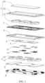
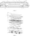
- the speaker A includes a diaphragm assembly 2 and a magnetic circuit assembly 1.
- the diaphragm assembly 2 includes at least two voice coils 21.
- the magnetic circuit assembly 1 includes first magnets 12 and a second magnet 11.
- a plurality of first magnets 12 are disposed around the second magnet 11.
- a vent groove 13 is disposed between two adjacent first magnets 12.
- the voice coil 21 is disposed between the second magnet 11 and the first magnet 12.
- the speaker A includes at least two magnetic circuit assemblies 1.
- the magnetic circuit assembly 1 is disposed corresponding to the voice coil 21. Two adjacent magnetic circuit assemblies 1 share a same first magnet 12. When the voice coil 21 moves relative to the magnetic circuit assembly 1, the vent groove 13 is configured to exhaust air.
- the diaphragm assembly 2 is connected to the magnetic circuit assembly 1.
- the magnetic circuit assembly 1 is configured to provide a magnetic field, and the diaphragm assembly 2 can vibrate and emit a sound in the magnetic field.
- the magnetic circuit assembly 1 includes the first magnets 12 and the second magnet 11.
- the first magnets 12 may be side magnets, and the second magnet 11 may be a central magnet.
- the side magnets are disposed around the central magnet.
- Two adjacent magnetic circuit assemblies 1 share one side magnet.
- a plurality of voice coils 21 may be connected in series, parallel, or a series-parallel combination according to an actual requirement. Each voice coil 21 is disposed between the side magnet and the central magnet. When the voice coil 21 is energized, a current may be generated in the voice coil 21, and therefore a magnetic field is generated.
- the voice coil 21 moves under a force in the magnetic field generated by the magnetic circuit assembly 1.
- the magnetic field generated by the voice coil 21 also changes.
- the change may be a change in a value of the current or a change in a direction of the current. Therefore, the voice coil 21 vibrates back and forth, and the voice coil 21 cooperates with the diaphragm assembly 2 to emit a sound.
- the magnetic circuit assembly 1 provided in this embodiment of this application is of a design of a five magnetic circuit system, and can provide a strong magnetic field, to improve a driving force of the speaker A.
- Specific sizes of the first magnet 12 and the second magnet may be set according to an actual requirement.
- Adjacent first magnets 12 may be disposed perpendicular to each other to form a rectangle.
- the second magnet 11 is disposed in the center of the rectangle.
- the coil may also be correspondingly disposed as a rectangle and disposed between the first magnet 12 and the second magnet 11.
- vent grooves 13 All four corners of the rectangle formed by the first magnets 12 can form vent grooves 13. Therefore, in addition to four corners of the speaker A, there is also a vent groove 13 in a length direction of the speaker A, so that an area of the vent groove 13 is increased, and air can be exhausted from a plurality of directions. This improves exhaust efficiency, and therefore increases a Q value of the speaker A.
- the vent grooves 13 are disposed at the four corners of the magnetic circuit assembly 1, so that impact on the magnetic field can be reduced, and the magnetic circuit assembly 1 can provide a strong magnetic field.
- a size of at least one voice coil 21 is different from a size of a remaining voice coil 21.
- the size of the at least one voice coil 21 may be set to be larger than that of another voice coil 21.
- a voice coil 21 of a larger size can achieve better support effect, to mitigate segmented vibration caused by insufficient stiffness of the diaphragm assembly 2.
- the voice coil 21 is energized and vibrates in the magnetic field generated by the magnetic circuit assembly 1, a diaphragm 22 can be driven to vibrate and emit a sound.
- the diaphragm assembly 2 is not a complete rigid body.
- the diaphragm 22 in the diaphragm assembly 2 deforms when the diaphragm 22 moves.
- the size of the at least one voice coil 21 is set to be different from that of the remaining voice coil 21. Specifically, a size of one voice coil 21 may be set to be larger than that of the remaining voice coil 21. This improves support effect on the diaphragm assembly 2, and reduces impact of segmented vibration on the speaker A.
- the diaphragm assembly 2 includes three voice coils 21, and the voice coils 21 are sequentially disposed in the length direction of the speaker A.
- a size of a voice coil 21 located in the middle is larger than sizes of voice coils 21 located on two sides.
- the voice coil 21 of the largest size is disposed in the middle, and the voice coils 21 of the smaller sizes are disposed on the two sides of the voice coil 21 of the largest size.
- the voice coil 21 of the largest size can well support the diaphragm 22, to mitigate segmented vibration caused by insufficient stiffness of a central region of the diaphragm 22, and improve fidelity of the speaker A.
- a size of the second magnet 11 is directly proportional to a size of the voice coil 21 corresponding to the magnetic circuit assembly 1.
- the size of the second magnet 11 is correspondingly set based on the size of the voice coil 21, and a position at which the first magnet 12 is disposed also matches the size of the voice coil 21. In this way, the magnetic circuit assembly 1 can well cooperate with the voice coil 21, and the speaker A has a sufficient driving force.
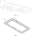
- the speaker A includes a basket component 5.
- the basket component 5 is disposed in a circumferential direction of the speaker A.
- the basket component 5 is provided with an exhaust groove 51.
- the exhaust groove 51 is disposed in an inner ring of the basket component 5 in a length direction of the speaker A, and may be disposed at an edge position of the inner ring of the basket component.
- the basket component 5 is made of metal.
- the speaker A further includes a basket component 5.
- the basket component 5 formed integrally by a basket and a ring washer, is disposed around an edge of the speaker A, and is configured to fasten and mount the magnetic circuit assembly 1 and reduce magnetic force dispersion.
- the basket component 5 is provided with the exhaust groove 51.
- the exhaust groove 51 is disposed at the edge of the inner ring of the basket component 5 in the length direction of the speaker A, and the exhaust groove 51 is recessed in a direction far away from the magnetic circuit assembly 1.
- the exhaust groove 51 is disposed between two magnetic circuit assemblies 1, and may be specifically disposed between two adjacent side magnets. In this way, magnetic force dispersion effect on the magnetic field is small, and the exhaust groove 51 can improve exhaust efficiency, and increase the Q value of the speaker A.
- the basket component 5 can support the magnetic circuit assembly 1, and a hole corresponding to the magnetic circuit assembly 1 is provided on the basket component 5.
- the basket component 5 can reduce a deviation of the voice coil 21 in the length direction and a width direction of the speaker A, and reduce a possibility that the voice coil 21 deviates and collides with a side washer and a central washer.
- the basket component 5 is made of metal, can achieve good magnetic conductivity effect, and has sufficient strength, so that a possibility of bending and deformation during assembly is reduced.
- the speaker A includes a framework 7.
- the diaphragm assembly 2 includes a diaphragm 22 and a ball dome 23.
- the framework 7 is disposed between the basket component 5 and the diaphragm 22.
- the ball dome 23 is disposed on a side that is of the diaphragm 22 and that is far away from the basket component 5.
- the diaphragm 22 is a sound radiation component of the speaker A and has great impact on sound-emitting performance of the speaker A.
- the diaphragm 22 needs to rapidly respond to a rapidly changing signal and bear an air pressure generated during high-speed movement. Therefore, the diaphragm 22 needs to be light and has sufficient strength. In addition, the diaphragm 22 should not deform greatly under changes in ambient temperature and humidity. Otherwise, sound-emitting effect of the speaker A may be affected.
- the diaphragm 22 may usually be made of plastic, metal, or composite materials, and a shape and a structure of the diaphragm 22 may be set based on a quantity and a position of the magnetic circuit assembly 1.
- the diaphragm 22 is soft, and the hard ball dome 23 is configured to support the diaphragm 22.
- the framework 7 is configured to adjust a position of the voice coil 21, to improve symmetry of BL, cause vibration to be more linear, and improve the sound quality of the speaker A.
- a specific shape of the framework 7 may be set based on a specific position at which the voice coil 21 is disposed and a size in a thickness direction of the speaker A, to adjust the position of the voice coil 21.
- the speaker A includes a circuit board 71 and a small membrane 9.
- the circuit board 71 and a framework 7 are disposed integrally.
- the small membrane 9 is located on a side that is of the voice coil 21 and that is far away from the diaphragm 22, and is connected to the voice coil 21.
- the circuit board 71 is configured to electrically connect to the voice coil 21, so that the voice coil 21 is energized.
- the circuit board 71 may be a flexible circuit (FPC, Flexible Printed Circuit) board.
- the circuit board 71 considers a function of the framework 7, so that material costs can be reduced.
- the circuit board 71 and the framework 7 are disposed integrally to reduce internal space occupied by the circuit board 71 in the speaker A, so that utilization of internal space in the speaker A is improved.
- the small membrane 9 is disposed on the side that is of the voice coil 21 and that is far away from the diaphragm 22, and is connected to the basket component 5.
- the voice coil 21 may further move in a length direction and a width direction of the speaker A, finally affecting sound quality.
- the small membrane 9 may implement a buffer function when the voice coil 21 vibrates, to suppress nonlinear vibration of the voice coil 21. In this case, movement of the voice coil 21 is more linear, so that sound quality of the speaker A is improved.
- the speaker A includes a circuit board 71 and a small membrane 9.
- the small membrane 9 is located on a side that is of the voice coil 21 and that is far away from the diaphragm 22.
- the circuit board 71 is located on a side that is of the small membrane 9 and that is far away from the voice coil 21.
- the small membrane 9 is connected to the circuit board 71.
- the circuit board 71 and the framework 7 are disposed separately.
- the small membrane 9 and the circuit board 71 may be disposed between two adjacent second magnets 11, to improve space utilization, facilitating a design of a larger size of the voice coil 21.
- the small membrane 9 is disposed on the side that is of the voice coil 21 and that is far away from the diaphragm 22, and is connected to the basket component 5.
- the small membrane 9 is configured to suppress rocking of the voice coil 21, so that vibration of the voice coil 21 is more linear.
- the circuit board 71 is disposed on a side that is of the small membrane 9 and that is far away from the voice coil 21 and the diaphragm 22, and is configured to electrically connect to the voice coil 21.
- the speaker A further includes a yoke 6.
- the yoke 6 is configured to mount the magnetic circuit assembly 1.
- the yoke 6 is provided with an avoidance part 65.
- the avoidance part 65 is configured to avoid the circuit board 71.
- the yoke 6 is configured to position and mount the magnetic circuit assembly 1.
- the yoke 6 is provided with the avoidance part 65 configured to avoid the circuit board 71 connected to the small membrane 9, so that there is sufficient disposing space for the circuit board 71 in a thickness direction of the speaker A.
- the avoidance part 65 may be a notch or a concave provided at a position that corresponds to the circuit board 71 and that is on the yoke 6.
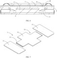
- the yoke 6 includes a first yoke 61, a second yoke 62, and a third yoke 63.
- the second yoke 62 is disposed between the first yoke 61 and the third yoke 63.
- the plurality of magnetic circuit assemblies 1 need to be positioned during mounting.
- the plurality of magnetic circuit assemblies 1 may be first mounted on the first yoke 61, the second yoke 62, and the third yoke 63 separately.
- the first yoke 61 and the third yoke 63 may each mount and position one magnetic circuit assembly 1, the second yoke 62 mounts and positions one magnetic circuit assembly 1, and then the first yoke 61, the second yoke 62, and the third yoke 63 are connected to each other.
- the split-style yoke 6 reduces a quantity of components of each part, and therefore reduces positioning difficulty of each part. This reduces overall difficulty of visual positioning and assembly, more accurately controls a magnetic gap, shortens a total magnetic gap tolerance chain, shortens an assembly period, and improves assembly precision and an assembly yield.
- the first yoke 61, the second yoke 62, and the third yoke 63 are provided with connecting parts 64, where a side that is of each of the first yoke 61 and the third yoke 63 and that is close to the second yoke 62 is provided with a connecting part 64, and two sides of the second yoke 62 are provided with connecting parts 64.
- the connecting part 64 facilitates the first yoke 61, the second yoke 62, and the third yoke 63 to be positioned and connected to each other.
- the connection may be performed in a connection manner such as bonding and welding.
- the connecting parts 64 are of a step shape, and the connecting parts 64 are capable of positioning and connecting to each other.
- the connecting part 64 may be disposed as a boss, so that a plurality of connecting parts 64 can be bonded to each other. This facilitates the first yoke 61 and the third yoke 63 to be positioned first. Then, the second yoke 62 between the first yoke 61 and the third yoke 63 is mounted. Finally, a connection is performed in a manner such as dot adhesive bonding or laser welding. During mounting, the first yoke 61 and the third yoke 63 may be positioned to a preset position, and positioned and mounted with the diaphragm 22.
- the second yoke 62, the first yoke 61, and the third yoke 63 are positioned at the same time, and the connecting part 64 of the second yoke 62 is connected to the connecting part 64 of each of the first yoke 61 and the third yoke 63. In this way, assembly of the speaker A is completed.
- the connecting part 64 may alternatively be disposed as cooperation between a protrusion part and a groove.
- a side wall of each of the first yoke 61 and the third yoke 63 is provided with a protrusion part
- a side wall of the third yoke 63 is provided with a groove.
- At least a part of the protrusion part can extend into the groove.
- a connection is performed in a manner such as dot adhesive or welding, so that the first yoke 61, the second yoke 62, and the third yoke 63 are connected.
- the separated magnetic circuit disposing is a special structural design for improving process concentricity control, that is, improving positioning accuracy.
- the plurality of magnetic circuit assemblies 1 may include a large quantity of magnetic gaps.
- the separated magnetic circuit design provided in embodiments of this application can improve positioning accuracy. In this way, an assembly yield in a scenario with an excessively large quantity of magnetic gaps is implemented, and feasibility of the solution is improved.
- the magnetic circuit assemblies 1 may be first mounted on the first yoke 61, the second yoke 62, and the third yoke 63 separately, and are connected to each other through the connecting part 64 for assembly, and then the diaphragm 22 is mounted.
- the diaphragm 22 may be mounted by using an auxiliary steel ring.
- at least a part of the diaphragm 22 needs to cover a side wall of the basket component 5, and the side wall of the basket component 5 is provided with a recess part, to enable the side wall to be flat after the basket component 5 is covered by the diaphragm 22.
- the auxiliary steel ring may be disposed at an edge of the basket component 5.
- a height of the auxiliary steel ring may be the same as a height of the recess part of the side wall of the basket component 5. Because a recess depth of the recess part is small, positioning and mounting are not convenient.
- the auxiliary steel ring can position and support the diaphragm 22, to facilitate mounting of the diaphragm 22. After the diaphragm 22 is mounted, the auxiliary steel ring is removed.
- the yoke 6 is provided with an avoidance structure 66 mounting part for mounting the avoidance structure 66.
- the speaker A needs to perform an electrical connection by using the conductive member.
- the conductive member may be disposed at a position at which the avoidance structure 66 is located. A quantity and a position of the avoidance structure 66 may be set based on an actual situation of the conductive member.
- the conductive member may be disposed based on a connection manner such as a serial connection and a parallel connection of the voice coil 21.
- the avoidance structure 66 is configured to reserve a position for installing the conductive member on the yoke 6, and the conductive member may not protrude from a surface of the speaker A, so that the surface of the speaker A is flat.
- the conductive member includes a positive conductive pad and a negative conductive pad that perform a conduction function.
- the speaker A includes a support frame 8.
- the support frame 8 is mounted on the yoke 6.
- a side wall of the support frame 8 is provided with an exhaust vent 81.
- the exhaust vent 81 is disposed corresponding to the vent groove 13.
- the support frame 8 may be integrally formed. A position that is of the support frame 8 and that corresponds to the vent groove 13 is provided with the exhaust vent 81, to facilitate exhaust of the vent groove 13.
- the support frame 8 may be disposed according to an actual requirement, and a full filling solution is implemented. This facilitates cost control.
- the support frame 8 is provided with a support part 82, and the support part 82 is disposed corresponding to the avoidance part 65.
- the yoke 6 is provided with the avoidance part 65 to avoid the circuit board 71.
- the support part 82 is provided at a corresponding position at the bottom of the support frame 8, and the support part 82 can cooperate with the avoidance part 65 to protect an internal structure of the speaker A.
- the speaker A includes a first washer 3 and a second washer 4.
- the first washer 3 is disposed on the second magnet 11, and the second washer 4 is disposed on the first magnet 12.
- the first washer 3 may be a central washer
- the second washer 4 may be a side washer.
- the side washer and the central washer are configured to connect to and fasten the side magnet and the central magnet, and can further achieve magnetic conduction effect.
- N poles and S poles of the central magnet and the side magnet are concentrated in a gap between the central magnet and the side magnet through a loop, so that a strong magnetic field exists in the gap, and the voice coil 21 located in the gap can be affected by the strong magnetic field.
- an embodiment of this application provides an electronic device B.
- the electronic device B includes a housing and a speaker A mounted on the housing.
- the speaker A is the speaker A in any one of the foregoing embodiments.
- the speaker A includes a diaphragm assembly 2 and a magnetic circuit assembly 1.
- the diaphragm assembly 2 includes at least two voice coils 21.
- the magnetic circuit assembly 1 includes first magnets 12 and a second magnet 11.
- the first magnets 12 are disposed around the second magnet 11.
- a vent groove 13 is disposed between two adjacent first magnets 12.
- the voice coil 21 is disposed between the second magnet 11 and the first magnet 12.
- the speaker A includes at least two magnetic circuit assemblies 1.
- the magnetic circuit assembly 1 is disposed corresponding to the voice coil 21. Two adjacent magnetic circuit assemblies 1 share a same first magnet 12.
Landscapes
- Engineering & Computer Science (AREA)
- Physics & Mathematics (AREA)
- Acoustics & Sound (AREA)
- Signal Processing (AREA)
- Multimedia (AREA)
- Manufacturing & Machinery (AREA)
- Audible-Bandwidth Dynamoelectric Transducers Other Than Pickups (AREA)
Applications Claiming Priority (2)
| Application Number | Priority Date | Filing Date | Title |
|---|---|---|---|
| CN202222068783.XU CN218734927U (zh) | 2022-08-05 | 2022-08-05 | 一种扬声器及电子设备 |
| PCT/CN2023/110918 WO2024027787A1 (fr) | 2022-08-05 | 2023-08-03 | Haut-parleur et dispositif électronique |
Publications (2)
| Publication Number | Publication Date |
|---|---|
| EP4492821A1 true EP4492821A1 (fr) | 2025-01-15 |
| EP4492821A4 EP4492821A4 (fr) | 2025-10-01 |
Family
ID=85629585
Family Applications (1)
| Application Number | Title | Priority Date | Filing Date |
|---|---|---|---|
| EP23849491.8A Pending EP4492821A4 (fr) | 2022-08-05 | 2023-08-03 | Haut-parleur et dispositif électronique |
Country Status (4)
| Country | Link |
|---|---|
| US (1) | US20250324204A1 (fr) |
| EP (1) | EP4492821A4 (fr) |
| CN (1) | CN218734927U (fr) |
| WO (1) | WO2024027787A1 (fr) |
Families Citing this family (5)
| Publication number | Priority date | Publication date | Assignee | Title |
|---|---|---|---|---|
| CN217904644U (zh) * | 2022-05-16 | 2022-11-25 | 华为技术有限公司 | 一种扬声器及电子设备 |
| CN218734927U (zh) * | 2022-08-05 | 2023-03-24 | 华为技术有限公司 | 一种扬声器及电子设备 |
| CN117082418B (zh) * | 2023-10-16 | 2024-02-20 | 瑞声光电科技(常州)有限公司 | 发声器件 |
| CN120111415B (zh) * | 2023-11-28 | 2026-01-09 | 荣耀终端股份有限公司 | 一种内核、扬声器模组及电子设备 |
| CN222423998U (zh) * | 2024-05-10 | 2025-01-28 | 深圳市维仕声学有限公司 | 微型扬声器 |
Family Cites Families (10)
| Publication number | Priority date | Publication date | Assignee | Title |
|---|---|---|---|---|
| CN205610929U (zh) * | 2016-04-21 | 2016-09-28 | 江西联创宏声电子有限公司 | 一种改善增强低频和摇摆振动的微型扬声器模组 |
| CN108650603A (zh) * | 2018-08-01 | 2018-10-12 | 歌尔股份有限公司 | 发声器件及便携终端 |
| CN110753290B (zh) * | 2019-09-30 | 2021-01-08 | 歌尔科技有限公司 | 发声装置及安装有该发声装置的声学模块及电子设备 |
| CN210868143U (zh) * | 2020-02-28 | 2020-06-26 | 歌尔股份有限公司 | 发声装置 |
| CN111510830B (zh) * | 2020-04-16 | 2025-04-01 | 歌尔股份有限公司 | 发声装置 |
| CN213426388U (zh) * | 2020-09-25 | 2021-06-11 | 瑞声科技(新加坡)有限公司 | 扬声器箱及移动终端 |
| CN113099365A (zh) * | 2021-04-01 | 2021-07-09 | 歌尔股份有限公司 | 发声装置和电子设备 |
| CN114374915B (zh) * | 2021-12-30 | 2024-09-17 | 歌尔股份有限公司 | 发声单体、发声模组和电子设备 |
| CN217904644U (zh) * | 2022-05-16 | 2022-11-25 | 华为技术有限公司 | 一种扬声器及电子设备 |
| CN218734927U (zh) * | 2022-08-05 | 2023-03-24 | 华为技术有限公司 | 一种扬声器及电子设备 |
-
2022
- 2022-08-05 CN CN202222068783.XU patent/CN218734927U/zh active Active
-
2023
- 2023-08-03 EP EP23849491.8A patent/EP4492821A4/fr active Pending
- 2023-08-03 WO PCT/CN2023/110918 patent/WO2024027787A1/fr not_active Ceased
- 2023-08-03 US US18/869,119 patent/US20250324204A1/en active Pending
Also Published As
| Publication number | Publication date |
|---|---|
| CN218734927U (zh) | 2023-03-24 |
| US20250324204A1 (en) | 2025-10-16 |
| WO2024027787A1 (fr) | 2024-02-08 |
| EP4492821A4 (fr) | 2025-10-01 |
Similar Documents
| Publication | Publication Date | Title |
|---|---|---|
| EP4492821A1 (fr) | Haut-parleur et dispositif électronique | |
| EP4525484A1 (fr) | Haut-parleur et dispositif électronique | |
| US12289589B2 (en) | Electroacoustic transducer, speaker module, and electronic device | |
| US11917362B2 (en) | Speaker box | |
| US20210274289A1 (en) | Sound device and portable terminal | |
| CN114363778B (zh) | 发声装置和电子设备 | |
| EP2770752A2 (fr) | Micro-haut-parleur de type aimant annulaire interne | |
| US20210266671A1 (en) | Sound Production Device and Portable Terminal | |
| WO2024050885A1 (fr) | Dispositif de production sonore multifonctionnel | |
| US20230179921A1 (en) | Speaker | |
| CN118678270A (zh) | 发声装置和电子设备 | |
| CN120282072A (zh) | 发声装置、发声模组及电子设备 | |
| CN120282070A (zh) | 发声装置、发声模组及电子设备 | |
| CN118678268A (zh) | 发声装置和电子设备 | |
| US11665480B2 (en) | Speaker | |
| US11997465B2 (en) | Speaker device | |
| US11765514B2 (en) | Speaker | |
| US12149910B2 (en) | Speaker | |
| CN114501251B (zh) | 发声装置和电子设备 | |
| CN210694295U (zh) | 振膜及采用该振膜的受话器 | |
| CN212211376U (zh) | 一种新型扬声器 | |
| CN222814595U (zh) | 发声装置和电子设备 | |
| US11722823B2 (en) | Speaker | |
| CN222814594U (zh) | 发声装置和电子设备 | |
| US20260052348A1 (en) | Loudspeaker, loudspeaker module and electronic device |
Legal Events
| Date | Code | Title | Description |
|---|---|---|---|
| STAA | Information on the status of an ep patent application or granted ep patent |
Free format text: STATUS: THE INTERNATIONAL PUBLICATION HAS BEEN MADE |
|
| PUAI | Public reference made under article 153(3) epc to a published international application that has entered the european phase |
Free format text: ORIGINAL CODE: 0009012 |
|
| STAA | Information on the status of an ep patent application or granted ep patent |
Free format text: STATUS: REQUEST FOR EXAMINATION WAS MADE |
|
| 17P | Request for examination filed |
Effective date: 20241009 |
|
| AK | Designated contracting states |
Kind code of ref document: A1 Designated state(s): AL AT BE BG CH CY CZ DE DK EE ES FI FR GB GR HR HU IE IS IT LI LT LU LV MC ME MK MT NL NO PL PT RO RS SE SI SK SM TR |
|
| RIC1 | Information provided on ipc code assigned before grant |
Ipc: H04R 9/04 20060101ALI20250528BHEP Ipc: H04R 31/00 20060101ALI20250528BHEP Ipc: H04R 7/04 20060101ALI20250528BHEP Ipc: H04R 9/02 20060101ALI20250528BHEP Ipc: H04R 9/06 20060101AFI20250528BHEP |
|
| A4 | Supplementary search report drawn up and despatched |
Effective date: 20250903 |
|
| RIC1 | Information provided on ipc code assigned before grant |
Ipc: H04R 9/06 20060101AFI20250828BHEP Ipc: H04R 9/02 20060101ALI20250828BHEP Ipc: H04R 7/04 20060101ALI20250828BHEP Ipc: H04R 31/00 20060101ALI20250828BHEP Ipc: H04R 9/04 20060101ALI20250828BHEP |
|
| DAV | Request for validation of the european patent (deleted) | ||
| DAX | Request for extension of the european patent (deleted) |