EP4492900A1 - Kommunikationsverfahren und -vorrichtung - Google Patents
Kommunikationsverfahren und -vorrichtung Download PDFInfo
- Publication number
- EP4492900A1 EP4492900A1 EP23778370.9A EP23778370A EP4492900A1 EP 4492900 A1 EP4492900 A1 EP 4492900A1 EP 23778370 A EP23778370 A EP 23778370A EP 4492900 A1 EP4492900 A1 EP 4492900A1
- Authority
- EP
- European Patent Office
- Prior art keywords
- dci
- field
- ccs
- pdsch
- time unit
- Prior art date
- Legal status (The legal status is an assumption and is not a legal conclusion. Google has not performed a legal analysis and makes no representation as to the accuracy of the status listed.)
- Pending
Links
Images





Classifications
-
- H—ELECTRICITY
- H04—ELECTRIC COMMUNICATION TECHNIQUE
- H04W—WIRELESS COMMUNICATION NETWORKS
- H04W72/00—Local resource management
- H04W72/20—Control channels or signalling for resource management
- H04W72/23—Control channels or signalling for resource management in the downlink direction of a wireless link, i.e. towards a terminal
- H04W72/232—Control channels or signalling for resource management in the downlink direction of a wireless link, i.e. towards a terminal the control data signalling from the physical layer, e.g. DCI signalling
-
- H—ELECTRICITY
- H04—ELECTRIC COMMUNICATION TECHNIQUE
- H04W—WIRELESS COMMUNICATION NETWORKS
- H04W72/00—Local resource management
- H04W72/20—Control channels or signalling for resource management
- H04W72/23—Control channels or signalling for resource management in the downlink direction of a wireless link, i.e. towards a terminal
- H04W72/231—Control channels or signalling for resource management in the downlink direction of a wireless link, i.e. towards a terminal the control data signalling from the layers above the physical layer, e.g. RRC or MAC-CE signalling
-
- H—ELECTRICITY
- H04—ELECTRIC COMMUNICATION TECHNIQUE
- H04L—TRANSMISSION OF DIGITAL INFORMATION, e.g. TELEGRAPHIC COMMUNICATION
- H04L1/00—Arrangements for detecting or preventing errors in the information received
- H04L1/12—Arrangements for detecting or preventing errors in the information received by using return channel
- H04L1/16—Arrangements for detecting or preventing errors in the information received by using return channel in which the return channel carries supervisory signals, e.g. repetition request signals
- H04L1/18—Automatic repetition systems, e.g. Van Duuren systems
- H04L1/1812—Hybrid protocols; Hybrid automatic repeat request [HARQ]
-
- H—ELECTRICITY
- H04—ELECTRIC COMMUNICATION TECHNIQUE
- H04L—TRANSMISSION OF DIGITAL INFORMATION, e.g. TELEGRAPHIC COMMUNICATION
- H04L5/00—Arrangements affording multiple use of the transmission path
- H04L5/003—Arrangements for allocating sub-channels of the transmission path
- H04L5/0048—Allocation of pilot signals, i.e. of signals known to the receiver
-
- H—ELECTRICITY
- H04—ELECTRIC COMMUNICATION TECHNIQUE
- H04L—TRANSMISSION OF DIGITAL INFORMATION, e.g. TELEGRAPHIC COMMUNICATION
- H04L5/00—Arrangements affording multiple use of the transmission path
- H04L5/0091—Signalling for the administration of the divided path, e.g. signalling of configuration information
- H04L5/0094—Indication of how sub-channels of the path are allocated
-
- H—ELECTRICITY
- H04—ELECTRIC COMMUNICATION TECHNIQUE
- H04W—WIRELESS COMMUNICATION NETWORKS
- H04W72/00—Local resource management
- H04W72/04—Wireless resource allocation
- H04W72/044—Wireless resource allocation based on the type of the allocated resource
- H04W72/0446—Resources in time domain, e.g. slots or frames
-
- H—ELECTRICITY
- H04—ELECTRIC COMMUNICATION TECHNIQUE
- H04W—WIRELESS COMMUNICATION NETWORKS
- H04W72/00—Local resource management
- H04W72/12—Wireless traffic scheduling
- H04W72/1263—Mapping of traffic onto schedule, e.g. scheduled allocation or multiplexing of flows
- H04W72/1273—Mapping of traffic onto schedule, e.g. scheduled allocation or multiplexing of flows of downlink data flows
-
- H—ELECTRICITY
- H04—ELECTRIC COMMUNICATION TECHNIQUE
- H04W—WIRELESS COMMUNICATION NETWORKS
- H04W72/00—Local resource management
- H04W72/04—Wireless resource allocation
- H04W72/044—Wireless resource allocation based on the type of the allocated resource
- H04W72/0453—Resources in frequency domain, e.g. a carrier in FDMA
Definitions
- Embodiments of this application relate to the field of communication technologies, and in particular, to a communication method and apparatus.
- Carrier aggregation is a technology in which two or more component carriers (component carriers, CCs) are aggregated to support a larger transmission bandwidth. Each CC corresponds to one independent cell. Usually, one CC may be equivalent to one cell.
- the CA supports aggregation of different CCs, for example, aggregation of CCs in a same bandwidth or different bandwidths; aggregation of adjacent or non-adjacent CCs in a same frequency band; and aggregation of CCs in different frequency bands.
- DCI downlink control information
- This application provides a communication method and apparatus, to schedule data transmission in a plurality of CCs by using first DCI, and implement carrier aggregation of the plurality of CCs.
- a communication method is provided.
- the method is performed by a network device, a component (a processor, a chip, or the like) disposed in the network device, or the like.
- the method includes: sending first downlink control information DCI to a terminal.
- the first DCI is for scheduling transmission of a plurality of component carriers CCs, the first DCI includes a first field, and information carried in the first field is shared by the plurality of CCs.
- information k0 carried in the first field is configured to be shared by the plurality of CCs, k0 indicates an offset value between a first reference location and a time unit corresponding to a physical downlink shared channel PDSCH, and the first reference location is determined based on a time unit corresponding to the first DCI.
- the first DCI when the plurality of CCs are scheduled by using the first DCI, the first DCI includes at least the first field.
- the first field is shared by the plurality of CCs, and independent information does not need to be configured for each CC in the first field, so that payload overheads of the first DCI are reduced.
- the first field may include a time domain resource assignment field.
- information k0 carried in the time domain resource assignment field is configured to be shared by the plurality of CCs, a design of k0 is described in detail, so that one value of k0 can indicate time units corresponding to PDSCHs in the plurality of CCs, to reduce the payload overheads of the first DCI.
- the first DCI further includes a second field, and information carried in the second field is independently configured for each of the plurality of CCs.
- the method further includes: determining, based on a configuration state of a field in the first DCI, corresponding information carried in the field in the first DCI.
- Configuration states of the field in the first DCI include: common, flexible, and independent. For one field in the first DCI, when a configuration state of the field is common, information carried in the field is shared by the plurality of CCs scheduled by using the first DCI; or when a configuration state of the field is flexible, information carried in the field is shared by the plurality of CCs scheduled by using the first DCI, or information carried in the field includes information independently configured for each CC; or when a configuration state of the field is independent, information carried in the field includes information independently configured for each CC.
- a field configuration state of each field in the first DCI may be specified in a protocol or preset.
- a configuration state of one field When a configuration state of one field is common, information carried in the field may be shared by the plurality of CCs. Alternatively, when a configuration state of one field is independent, information carried in the field is independently configured for each CC. Alternatively, when a configuration state of one field is flexible, information carried in the field may be shared by the plurality of CCs, or may be independently configured for each CC.
- a base station may determine, based on a field configuration state specified in a protocol, whether each field in the first DCI is common or independent. This is easy to be implemented by the base station.
- a field whose configuration state is common includes at least one of the following: an identifier for DCI formats, a carrier indicator, a downlink assignment index, a transmission power control TPC command for scheduled physical uplink control channel PUCCH, a PUCCH resource indicator, a transmission configuration indicator, or cyclic redundancy check CRC.
- k1 when information k1 carried in the first field is configured to be shared by the plurality of CCs, k1 indicates an offset value between a second reference location and a time unit corresponding to a HARQ, and the second reference location is determined based on a time unit corresponding to a PDSCH in at least one of the plurality of CCs.
- the first field includes a PDSCH-to-HARQ feedback timing indicator field.
- information k1 carried in the PDSCH-to-HARQ feedback timing indicator field may be shared by the plurality of CCs, a value of k1 may be carried, to indicate time units for sending HARQs on the plurality of CCs, and reduce the payload overheads of the first DCI.
- the plurality of CCs scheduled by using the first DCI include at least a first CC and a second CC.
- the first DCI is sent to the terminal on the first CC.
- the method further includes: sending second DCI to the terminal on the first CC.
- the first DCI is DCI that supports multi-carrier co-scheduling
- the second DCI is DCI that supports single-carrier scheduling.
- the second DCI may be further sent on the first CC.
- the first DCI may be the DCI that supports multi-carrier scheduling.
- the first DCI may be single DCI.
- the second DCI may be the DCI that supports single-carrier scheduling.
- the second DCI is single DCI or legacy DCI.
- the first DCI and the second DCI are sent in a same time unit.
- the first DCI is sent by using N time units as a periodicity
- the second DCI is sent in time units between different periodicities of the first DCI
- a value of N is determined based on the SCS of the first CC and the SCS of the second CC.
- a design when a plurality of data transmissions are scheduled on one CC by using the first DCI, information carried in any one of the following fields included in the first DCI is shared by the plurality of data transmissions on the CC: frequency domain resource assignment, a modulation and coding scheme MCS of a transport block TB, a new data indicator of a TB, or a redundancy version RV of a TB.
- a plurality of data transmissions may be scheduled on a same CC by using the first DCI, and the data transmission may be carried on a PDSCH or a PUSCH.
- the data transmission may be carried on a PDSCH or a PUSCH.
- a field in DCI may be further shared for a plurality of data transmissions on a same CC, so that the payload overheads of the first DCI are reduced.
- the group of offset values k0 when there are a group of offset values k0, the group of offset values k0 include a plurality of offset values k0, the group of offset values k0 are shared by the plurality of CCs scheduled by using the first DCI, and the plurality of offset values k0 included in the group of offset values k0 are independently configured for a plurality of data transmissions scheduled on one CC by using the first DCI.
- a communication method is provided.
- the method is performed by a terminal or a component (a processor, a chip, or the like) disposed in the terminal.
- the method includes: receiving first downlink control information DCI from a network device.
- the first DCI is for scheduling transmission of a plurality of component carriers CCs, the first DCI includes a first field, and information carried in the first field is shared by the plurality of CCs.
- information k0 carried in the first field is configured to be shared by the plurality of CCs, k0 indicates an offset value between a first reference location and a time unit corresponding to a physical downlink shared channel PDSCH, and the first reference location is determined based on a time unit corresponding to the first DCI.
- data transmission on a plurality of CCs may be scheduled by using the first DCI.
- the first field in the DCI may be designed to be shared by the plurality of CCs, and corresponding information does not need to be independently configured for each CC, so that payload overheads of the first DCI are reduced.
- the first DCI further includes a second field, and information carried in the second field is independently configured for each of the plurality of CCs.
- configuration states of a field in the first DCI include: common, flexible, and independent, and at least one of the first field and the second field is determined based on a configuration state that is of a field in the first DCI and that is specified in a protocol.
- a field whose configuration state is common includes at least one of the following: an identifier for DCI formats, a carrier indicator, a downlink assignment index, a transmission power control TPC command for scheduled physical uplink control channel PUCCH, a PUCCH resource indicator, a transmission configuration indicator, or cyclic redundancy check CRC.
- the plurality of CCs scheduled by using the first DCI include a first CC and a second CC
- a subcarrier spacing SCS of the first CC is less than an SCS of the second CC
- the first reference location is a time unit corresponding to first DCI on the second CC
- k0 indicates an offset value between the time unit corresponding to the first DCI on the second CC and a time unit corresponding to a PDSCH
- the method further includes: determining, based on the SCS of the first CC, the SCS of the second CC, and k0, an offset value between the time unit corresponding to the first DCI and the time unit corresponding to the PDSCH on the first CC.
- the determining, based on the SCS of the first CC, the SCS of the second CC, and k0, an offset value between the time unit corresponding to the first DCI on the first CC and the time unit corresponding to the PDSCH satisfies the following condition: floor k 0 / 2 ⁇ 1 ⁇ ⁇ 2 , where floor represents a round-down operation, k0 represents the offset value between the time unit corresponding to the first DCI on the second CC and the time unit corresponding to the PDSCH, ⁇ 1 represents an index of the SCS corresponding to the second CC, and ⁇ 2 represents an index of the SCS corresponding to the first CC.
- the plurality of CCs scheduled by using the first DCI include a first CC and a second CC, an SCS of the first CC is less than an SCS of the second CC, the first reference location is an offset value between the time unit corresponding to the first DCI and the time unit corresponding to the PDSCH on the first CC, k0 indicates an offset value between the time unit corresponding to the first DCI and the time unit corresponding to the PDSCH on the first CC, and the method further includes: determining, based on the time unit corresponding to the PDSCH on the first CC, the time unit corresponding to the PDSCH on the second CC; or receiving indication information from the network device, where the indication information indicates an offset value between a time unit corresponding to first DCI on the second CC and the time unit corresponding to the PDSCH; or determining, based on a third field in the first DCI, a time unit corresponding to a PDSCH on the second CC, where the third field indicates an offset value
- k1 carried in the first field when information k1 carried in the first field is configured to be shared by the plurality of CCs, k1 indicates an offset value between a second reference location and a time unit for transmitting a HARQ, the second reference location is determined based on a time unit corresponding to a PDSCH in one of the plurality of CCs, and the method further includes: determining, based on the second reference location and k1, a time unit corresponding to a HARQ in the plurality of CCs of the first DCI.
- the plurality of CCs scheduled by using the first DCI include at least the first CC and the second CC.
- the first DCI is received from the network device on the first CC.
- the method further includes: receiving second DCI from the network device on the first CC.
- the first DCI is DCI that supports multi-carrier co-scheduling
- the second DCI is DCI that supports single-carrier scheduling.
- the first DCI and the second DCI are received in a same time unit.
- the first DCI is received by using N time units as a periodicity
- the second DCI is received in time units between different periodicities of the first DCI
- a value of N is determined based on the SCS of the first CC and the SCS of the second CC.
- a design when a plurality of data transmissions are scheduled on one CC by using the first DCI, information carried in any one of the following fields included in the first DCI is shared by the plurality of data transmissions on the CC: frequency domain resource assignment, a modulation and coding scheme MCS of a transport block TB, a new data indicator of a TB, or a redundancy version RV of a TB.
- the group of offset values k0 when there are a group of offset values k0, the group of offset values k0 include a plurality of offset values k0, the group of offset values k0 are shared by the plurality of CCs scheduled by using the first DCI, and the plurality of offset values k0 included in the group of offset values k0 are independently configured on a plurality of data transmissions scheduled on one CC by using the first DCI.
- a communication apparatus configured to implement the method in the first aspect, and includes corresponding functional modules or units, which are respectively configured to implement the steps in the method in the first aspect.
- Functions may be implemented by hardware, or may be implemented by hardware executing corresponding software.
- the hardware or the software includes one or more modules or units corresponding to the foregoing functions.
- a communication apparatus includes a processor and a memory.
- the memory is configured to store a computer program or instructions, and the processor is coupled to the memory.
- the processor executes the computer program or the instructions, the apparatus is enabled to perform the method in the first aspect.
- a communication apparatus configured to implement the method in the second aspect, and includes corresponding functional modules or units, which are respectively configured to implement the steps in the method in the second aspect.
- Functions may be implemented by hardware, or may be implemented by hardware executing corresponding software.
- the hardware or the software includes one or more modules or units corresponding to the foregoing functions.
- a communication apparatus includes a processor and a memory.
- the memory is configured to store a computer program or instructions, and the processor is coupled to the memory.
- the processor executes the computer program or the instructions, the apparatus is enabled to perform the method in the second aspect.
- a computer-readable storage medium stores a computer program or instructions.
- the computer program or the instructions are run on a computer, the computer is enabled to perform the method in the first aspect.
- a computer-readable storage medium stores a computer program or instructions.
- the computer program or the instructions are run on a computer, the computer is enabled to perform the method in the second aspect.
- a computer program product includes a computer program or instructions.
- the computer program or the instructions are run on a computer, the computer is enabled to perform the method in the first aspect.
- a computer program product includes a computer program or instructions.
- the computer program or the instructions are run on a computer, the computer is enabled to perform the method in the second aspect.
- a system includes the apparatus in the third aspect or the fourth aspect and the apparatus in the fifth aspect or the sixth aspect.
- FIG. 1 is a diagram of an architecture of a communication system 1000 to which this application is applicable.
- the communication system includes a radio access network 100 and a core network 200.
- the communication system 1000 may further include an internet 300.
- the radio access network 100 may include at least one access network device (for example, 110a and 110b in FIG. 1 ), and may further include at least one terminal (for example, 120a to 120j in FIG. 1 ).
- the terminal is connected to the access network device in a wireless manner, and the access network device is connected to the core network in a wireless or wired manner.
- a core network device and the access network device may be different physical devices that are independent of each other, or functions of a core network device and logical functions of the access network device may be integrated into a same physical device, or some of functions of a core network device and some of functions of the access network device may be integrated into one physical device.
- Terminals may be connected to each other in a wired or wireless manner, and access network devices may be connected to each other in a wired or wireless manner.
- FIG. 1 is merely a diagram.
- the communication system may further include another network device, for example, may further include a wireless relay device and a wireless backhaul device, which are not shown in FIG. 1 .
- the access network device may be a base station (base station), an evolved NodeB (evolved NodeB, eNodeB), a transmission reception point (transmission reception point, TRP), a next generation NodeB (next generation NodeB, gNB) in a 5th generation (5th generation, 5G) mobile communication system, an access network device in an open radio access network (open radio access network, O-RAN), a next generation base station in a 6th generation (6th generation, 6G) mobile communication system, a base station in a future mobile communication system, an access node in a wireless fidelity (wireless fidelity, Wi-Fi) system, or the like; or may be a module or a unit that completes some of functions of a base station, for example, may be a central unit (central unit, CU), a distributed unit (distributed unit, DU), a CU control plane (CU control plane, CU-CP) module, or a CU user plane (CU user plane, CU-UP) module.
- the access network device may be a macro base station (for example, 110a in FIG. 1 ), or may be a micro base station or an indoor base station (for example, 110b in FIG. 1 ), or may be a relay node, a donor node, or the like.
- a specific technology and a specific device form that are used by the access network device are not limited in this application.
- an apparatus configured to implement a function of the access network device may be an access network device, or may be an apparatus that can support the access network device in implementing the function, for example, a chip system, a hardware circuit, a software module, or a combination of the hardware circuit and the software module.
- the apparatus may be installed in the access network device or may be used together with the access network device.
- the chip system may include a chip, or may include a chip and another discrete component.
- the protocol layer structure may include a control plane protocol layer structure and a user plane protocol layer structure.
- the control plane protocol layer structure may include functions of protocol layers such as a radio resource control (radio resource control, RRC) layer, a packet data convergence protocol (packet data convergence protocol, PDCP) layer, a radio link control (radio link control, RLC) layer, a media access control (media access control, MAC) layer, and a physical layer.
- the user plane protocol layer structure may include functions of protocol layers such as a PDCP layer, an RLC layer, a MAC layer, and a physical layer.
- a service data adaptation protocol (service data adaptation protocol, SDAP) layer may be further included above the PDCP layer.
- An access device may include the CU and the DU.
- a plurality of DUs may be controlled by one CU in a centralized manner.
- an interface between the CU and the DU may be referred to as an F1 interface.
- a control plane (control plane, CP) interface may be F1-C
- a user plane (user plane, UP) interface may be F1-U.
- a specific name of each interface is not limited in this application.
- the CU and the DU may be divided based on protocol layers of a wireless network. For example, functions of a PDCP layer and a protocol layer above the PDCP layer are set on the CU, and functions of protocol layers (for example, an RLC layer and a MAC layer) below the PDCP layer are set on the DU. For another example, functions of a protocol layer above a PDCP layer are set on the CU, and functions of the PDCP layer and a protocol layer below the PDCP layer are set on the DU. This is not limited.
- the division into processing functions of the CU and the DU based on the protocol layers is merely an example, and there may be another division manner.
- the CU or the DU may be divided to have functions of more protocol layers.
- the CU or the DU may be further divided to have some processing functions of protocol layers.
- some of functions of the RLC layer and functions of a protocol layer above the RLC layer are set on the CU, and remaining functions of the RLC layer and functions of a protocol layer below the RLC layer are set on the DU.
- division of functions of the CU or the DU may alternatively be performed based on service types or other system requirements. For example, division may be performed based on latencies.
- the CU may alternatively have one or more functions of a core network.
- the CU may be disposed on a network side to facilitate centralized management.
- a radio unit (radio unit, RU) of the DU is disposed remotely.
- the RU may have a radio frequency function.
- the DU and the RU may be divided at a physical layer (physical layer, PHY).
- PHY physical layer
- the DU may implement higher-layer functions of the PHY layer
- the RU may implement lower-layer functions of the PHY layer.
- functions of the PHY layer may include at least one of the following: cyclic redundancy check (cyclic redundancy check, CRC) code addition, channel coding, rate matching, scrambling, modulation, layer mapping, precoding, resource mapping, physical antenna mapping, or radio frequency sending functions.
- cyclic redundancy check cyclic redundancy check, CRC
- functions of the PHY layer may include at least one of the following: CRC check, channel decoding, de-rate matching, descrambling, demodulation, layer demapping, channel detection, resource demapping, physical antenna demapping, or radio frequency receiving functions.
- the higher-layer functions of the PHY layer may include some functions of the PHY layer. For example, the functions are closer to the MAC layer.
- the lower-layer functions of the PHY layer may include the other functions of the PHY layer. For example, the functions are closer to the radio frequency function.
- the higher-layer functions of the PHY layer may include CRC code addition, channel coding, rate matching, scrambling, modulation, and layer mapping
- the lower-layer functions of the PHY layer may include precoding, resource mapping, physical antenna mapping, and radio frequency sending functions.
- the higher-layer functions of the PHY layer may include CRC code addition, channel coding, rate matching, scrambling, modulation, layer mapping, and precoding.
- the lower-layer functions of the PHY layer may include resource mapping, physical antenna mapping, and radio frequency sending functions.
- the higher-layer functions of the PHY layer may include CRC check, channel decoding, de-rate matching, decoding, demodulation, and layer demapping
- the lower-layer functions of the PHY layer may include channel detection, resource demapping, physical antenna demapping, and radio frequency receiving functions.
- the higher-layer functions of the PHY layer may include CRC check, channel decoding, de-rate matching, decoding, demodulation, layer demapping, and channel detection
- the lower-layer functions of the PHY layer may include resource demapping, physical antenna demapping, and radio frequency receiving functions.
- the functions of the CU may be implemented by one entity, or may be implemented by different entities.
- the functions of the CU may be further divided.
- a control plane and a user plane are separated and implemented by different entities: a control plane CU entity (that is, a CU-CP entity) and a user plane CU entity (that is, a CU-UP entity).
- the CU-CP entity and the CU-UP entity may be coupled to the DU, to jointly complete functions of an access network device.
- any one of the DU, the CU, the CU-CP, the CU-UP, and the RU may be a software module, a hardware structure, or a combination of the software module and the hardware structure.
- the DU, the CU, the CU-CP, and the CU-UP are software modules
- the RU is a hardware structure. The modules and methods performed by the modules also fall within the protection scope of this application.
- the access network device includes the CU-CP, the CU-UP, the DU, and the RU.
- this application is executed by the DU, or the DU and the RU, or the CU-CP, the DU, and the RU, or the CU-UP, the DU, and the RU. This is not limited. The methods performed by the modules also fall within the protection scope of this application.
- a terminal may also be referred to as a terminal device, user equipment (user equipment, UE), a mobile station, a mobile terminal, or the like.
- the terminal may be widely used in communication in various scenarios, for example, including but not limited to at least one of the following scenarios: device-to-device (device-to-device, D2D), vehicle-to-everything (vehicle-to-everything, V2X), machine-type communication (machine-type communication, MTC), an internet of things (internet of things, IoT), virtual reality, augmented reality, industrial control, self-driving, telemedicine, a smart grid, smart furniture, a smart office, a smart wearable, smart transportation, or a smart city.
- device-to-device device-to-device, D2D
- vehicle-to-everything vehicle-to-everything
- machine-type communication machine-type communication
- IoT internet of things
- virtual reality augmented reality
- industrial control self-driving
- the terminal may be a mobile phone, a tablet computer, a computer having a wireless transceiver function, a wearable device, a vehicle, an uncrewed aerial vehicle, a helicopter, an airplane, a ship, a robot, a mechanical arm, a smart home device, or the like.
- a specific technology and a specific device form that are used by the terminal are not limited in this application.
- an apparatus configured to implement a function of the terminal may be a terminal; or may be an apparatus that can support the terminal in implementing the function, for example, a chip system, a hardware circuit, a software module, or a combination of the hardware circuit and the software module.
- the apparatus may be installed in the terminal or may be used together with the terminal.
- the apparatus configured to implement the function of the terminal is UE.
- the base station and the terminal may be at fixed locations or movable.
- the base station and/or the terminal may be deployed on the land, including an indoor or outdoor scenario, and a handheld or vehicle-mounted scenario; or may be deployed on the water; or may be deployed on an airplane, a balloon, and an artificial satellite in the air.
- Application scenarios of the base station and the terminal are not limited in this application.
- the base station and the terminal may be deployed in a same scenario or different scenarios. For example, the base station and the terminal are both deployed on the land. Alternatively, the base station is deployed on the land, and the terminal is deployed on the water. Examples are not described one by one.
- Roles of the base station and the terminal may be relative.
- a helicopter or an uncrewed aerial vehicle 120i in FIG. 1 may be configured as a mobile base station, and for the terminal 120j accessing the radio access network 100 through 120i, the terminal 120i is a base station.
- the base station 110a 120i is a terminal.
- communication between 110a and 120i is performed based on a radio air interface protocol.
- communication between 110a and 120i may be performed based on an interface protocol between base stations.
- relative to 110a, 120i is also a base station. Therefore, the base station and the terminal may be collectively referred to as communication apparatuses, 110a and 110b in FIG. 1 each may be referred to as a communication apparatus having a base station function, and 120a to 120j in FIG. 1 each may be referred to as a communication apparatus having a terminal function.
- Communication between the base station and the terminal, between base stations, or between terminals may be performed by using a licensed spectrum, or may be performed by using an unlicensed spectrum, or may be performed by using both the licensed spectrum and the unlicensed spectrum. Communication may be performed by using a spectrum below 6 gigahertz (gigahertz, GHz), or may be performed by using a spectrum above 6 GHz, or may be performed by using both the spectrum below 6 GHz and the spectrum above 6 GHz.
- a spectrum resource used for wireless communication is not limited in this application.
- the base station sends a downlink signal or downlink information to the terminal.
- the downlink information is carried on a downlink channel.
- the terminal sends an uplink signal or uplink information to the base station.
- the uplink information is carried on an uplink channel.
- the terminal may establish a wireless connection to a cell controlled by the base station.
- the cell to which the terminal establishes the wireless connection is referred to as a serving cell of the terminal.
- the terminal may be interfered by a signal from a neighboring cell.
- a physical downlink shared channel (physical downlink shared channel, PDSCH), a physical downlink control channel (physical downlink control channel, PDCCH), a physical uplink shared channel (physical uplink shared channel, PUSCH), and a physical uplink control channel (physical uplink control channel, PUCCH) are merely examples of a downlink data channel, a downlink control channel, an uplink data channel, and an uplink control channel.
- a data channel and a control channel may have different names. This is not limited in embodiments of this application.
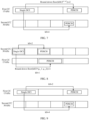
- a base station In a design, if a base station expects to schedule UE on a plurality of carriers to simultaneously perform PDSCH or PUSCH transmission, the base station needs to send a plurality of pieces of DCI for scheduling, and each carrier needs one piece of DCI for scheduling.
- a carrier on which DCI is sent there are two manners: self-carrier scheduling and cross-carrier scheduling.
- self-carrier scheduling DCI for scheduling a PDSCH or a PUSCH on the carrier is also sent on the carrier.
- self-carrier scheduling DCI and a PDSCH or a PUSCH scheduled by using the DCI are sent on a same CC. For example, as shown in FIG.
- DCI and a PDSCH or a PUSCH scheduled by using the DCI on the CC 1 are sent on a CC 1.
- DCI and a PDSCH or a PUSCH scheduled by using the DCI are sent on a CC 2.
- DCI for scheduling PDSCH or PUSCH transmission on the carrier is sent on another carrier, so that an effect that the DCI is sent on only one carrier is achieved.
- DCI and a PDSCH or a PUSCH scheduled by using the DCI may be sent on different CCs. For example, as shown in FIG. 3 , DCI is sent on a CC 1, and a PDSCH or a PUSCH is scheduled on a CC 2 by using the DCI.
- each piece of DCI is generally for scheduling one PDSCH or PUSCH.
- a solution of single DCI is proposed, and a plurality of PDSCHs or PUSCHs may all be scheduled by using the single DCI.
- the plurality of PDSCHs or PUSCHs may be on a same CC or different CCs. For example, a plurality of PDSCHs on a same CC may be scheduled by using the single DCI, or a plurality of PDSCHs on different CCs may be scheduled by using the single DCI.
- a plurality of PUSCHs on a same CC may be scheduled by using the single DCI, or a plurality of PUSCHs on different CCs may be scheduled by using the single DCI.
- a PDSCH and a PUSCH on a same CC, a PDSCH and a PUSCH on different CCs, or the like may be scheduled by using the single DCI.
- a PDSCH, a PUSCH, or the like scheduled by using the single DCI is used as an example, and is not intended to limit this application.
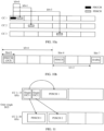
- another resource for example, a sidelink resource may be scheduled by using the single DCI. As shown in FIG.
- single DCI is sent on a CC 1, and both a PDSCH 1 on the CC 1 and a PDSCH 2 on a CC 2 may be scheduled by using the single DCI.
- a basic principle of a single DCI technology is that PDSCHs or PUSCHs on a plurality of carriers or CCs are scheduled by using single DCI.
- a PDSCH or a PUSCH on one carrier or CC is scheduled by using each piece of DCI, so that a quantity of pieces of DCI can be reduced, and overheads of a control channel can be reduced.
- single DCI includes a plurality of fields.
- a PDSCH or a PUSCH may be described as a PDSCH/PUSCH, and "/" represents an "or" relationship.
- This application provides a communication method.
- a plurality of PDSCHs or PUSCHs scheduled by using single DCI may share field information, to reduce payload overheads of the single DCI.
- a procedure of a communication method is provided, and includes at least the following steps.
- Step 501 A base station sends first DCI to UE, where the first DCI supports multi-carrier co-scheduling, and the first DCI is for scheduling transmission on a plurality of CCs.
- the first DCI may be referred to as single DCI.
- step 502 The UE receives PDSCHs or sends PUSCHs on the plurality of CCs based on scheduling of the first DCI.
- the first DCI includes a first field, and information carried in the first field is shared by the plurality of CCs.
- the first field is a general term for fields shared by the plurality of CCs, and the first field may be specifically one or more fields.
- a time domain resource assignment field and a PDSCH-to-hybrid automatic repeat request (hybrid automatic repeat request, HARQ) feedback timing indicator field each may be referred to as the first field.
- HARQ hybrid automatic repeat request
- the first field includes a plurality of fields, and each of the plurality of fields is shared by the plurality of CCs.
- the information carried in the first field may be information carried in any one of the fields shared by the plurality of CCs.
- information k0 carried in the first field may refer to information k0 carried in the time domain resource assignment field, and information k1 carried in the first field may be information k1 carried in the PDSCH-to-HARQ feedback timing indicator field.
- the first DCI further includes a second field, and information carried in the second field is independently configured for each of the plurality of CCs.
- a field in DCI may also be referred to as a DCI field, and information carried in the field in the DCI may be referred to as a field value.
- configuration states of a field in the first DCI include common, sub-group common, flexible, independent, and the like.
- a configuration state of each field may be specified in a protocol or predefined. This is not limited.
- the base station may determine, based on a configuration state of each field in the first DCI, corresponding information carried in the field in the first DCI.
- the field For a specific field in the first DCI, the field may be referred to as a target field, and information carried in the target field may be referred to as target information.
- the information carried in the target field is shared by the plurality of CCs scheduled by using the first DCI.
- the first DCI schedules PDSCHs or PUSCHs on a first CC and a second CC.
- the first DCI may determine the target information based on the PDSCH or the PUSCH on the first CC, or determine the target information based on the PDSCH or the PUSCH on the second CC, or determine the target information based on both the PDSCH or the PUSCH on the first CC and the PDSCH or the PUSCH on the second CC.
- the target field in the first DCI carries the target information, and the target information is shared by the first CC and the second CC.
- the target information carried in the target field is shared by a plurality of CCs included in one sub-group scheduled by using the first DCI, where the sub-group may include some of the plurality of CCs scheduled by using the first DCI.
- the target information carried in the target field is shared by the plurality of CCs scheduled by using the first DCI, or the target information carried in the target field is shared by a plurality of CCs included in one sub-group, or the information carried in the target field includes information independently configured for each CC. This is not limited.
- the target information carried in the target field includes information independently configured for each CC.
- a PDSCH 1 on the first CC and a PDSCH 2 on the second CC are scheduled by using the first DCI, and the target field in the first DCI carries target information 1 and target information 2.
- the UE may receive the PDSCH 1 based on the target information 1, receive the PDSCH 2 based on the target information 2.
- a field whose configuration state is common includes at least one of the following: an identifier for DCI formats, a carrier indicator, a downlink assignment index, a transmission power control (transmission power control, TPC) command for scheduled PUCCH, a PUCCH resource indicator, a transmission configuration indicator, a second TPC command for scheduled PUCCH, a one-shot HARQ-ACK request, a HARQ-ACK retransmission indicator, a priority indicator, a channel access indicator, a PUCCH cell indicator, or CRC.
- TPC transmission power control
- a field whose configuration state is flexible includes at least one of the following: a bandwidth part (bandwidth part, BWP) indicator, frequency domain resource assignment, time domain resource assignment, virtual resource block (virtual resource block, VRB)-to-physical resource block (physical resource block, PRB) mapping, a PRB bundling size indicator, a rate matching indicator, a zero power (zero power, ZP) channel state information-reference signal (channel state information-reference signal, CSI-RS) trigger, a HARQ process number, a PDSCH-to-HARQ feedback timing indicator, an antenna port and a number of layers, a sounding reference signal (sounding reference signal, SRS) request, code block group (code block group, CBG) transmission information, CBG flushing out information, demodulation reference signal (demodulation reference signal, DMRS) sequence initialization, an enhanced codebook indicator, a PDSCH group, a new feedback indicator, a number of requested PDSCH groups, a minimum scheduling available value, a secondary cell dor
- a field whose configuration state is independent includes at least one of the following: a modulation and coding scheme (modulation and coding scheme, MCS) of a transport block (transport block, TB) 1, a new data indicator of a TB 1, a redundancy version (redundancy version, RV) of a TB 1, an MCS of a TB 2, a new data indicator of a TB 2, or an RV of a TB 2.
- MCS modulation and coding scheme
- a field whose configuration state is sub-group common includes at least one of the following: frequency domain resource assignment, time domain resource assignment, an MCS, an MCS of a TB 1, an RV of a TB 1, an MCS of a TB 2, an RV of a TB 2, a TPC command for scheduled PUCCH, a transmission configuration indicator, a second TPC command for scheduled PUCCH, a one-shot HARQ-ACK request, a HARQ-ACK retransmission indicator, a priority indicator, a channel access indicator, or the like.
- Downlink data transmission for example, a PDSCH may be scheduled by using the first DCI.
- An example in which the first DCI, for scheduling downlink data transmission, is referred to as DL single DCI is used to describe a configuration of each field. Refer to Table 1.
- uplink data transmission for example, a PUSCH is scheduled by using the first DCI.
- the first DCI is referred to as single DCI.
- a plurality of CCs are co-scheduled by using the single DCI, and each CC corresponds to one cell.
- Cells co-scheduled by using the single DCI may be grouped, and cells in a group may further share more fields.
- specific sub-group division may be configured by the base station by using the RRC signaling.
- An optional division manner is to divide cells with close frequency bands (bands) into a same sub-group. For example, when frequency bands corresponding to the four cells co-scheduled by using the single DCI are respectively: 700 M, 800 M, 1.8 G, and 2.1 G, considering that frequency bands, that is, 700 M and 800 M, of two cells are close, the two cells of 700 M and 800 M may be configured as one sub-group. Similarly, two cells of 1.8 G and 2.1 G are configured as another sub-group.
- a configuration state of each field in the single DCI may be designed as follows:
- each co-scheduled cell needs a piece of corresponding indication information in the DCI.
- the field For a field configured as "sub-group common", that is, for a cell in a sub-group, an indication value of the field is shared by cells in the sub-group, and for cells in different subgroups, the field is still independently configured.
- the field carries only one piece of indication information, and the indication information is shared by a plurality of cells included in the sub-group.
- the indication information may be determined based on a state of one cell included in the sub-group, or may be jointly determined based on states of the plurality of cells included in the sub-group. This is not limited.
- an MCS field may be configured as "sub-group common".
- the cell 1 and the cell 2 belong to one sub-group, the sub-group may share one piece of MCS indication information, the MCS indication information may be determined based on a configuration of the cell 1 or the cell 2, and the MCS indication information may be denoted as A.
- the cell 3 and the cell 4 belong to another sub-group, the sub-group may share one piece of MAC indication information, the MSC indication information may be determined based on a configuration of the cell 3 or the cell 4, and the MCS indication information may be denoted as B.
- a and B perform independent indication.
- the MCS field may include two pieces of indication information: A and B.
- a frequency domain resource assignment field is configured as that cells in a same sub-group may be jointly indicated by using a field value.
- frequency domain resource assignment may be indicated in an indication manner, namely, Type 0, in which frequency domain resources are not allocated contiguously.
- assignment is performed at an RBG granularity, and indication is performed in a bitmap manner.
- a bitmap length is a quantity of RBGs in a BWP.
- the base station may flexibly configure a state by using RRC signaling, and optional configuration states include: “common”, “independent”, or "sub-group common”.
- a design in which a plurality of CCs are scheduled by using the first DCI can significantly reduce overheads of a control channel, release more downlink resources for PDSCH transmission, and improve a downlink capacity.
- a sharing design for a specific field in the first DCI reduces overheads of a size of the DCI, and ensures system coverage performance.
- configuration states of the time domain resource assignment field and the PDSCH-to-HARQ feedback timing indicator field in the first DCI are flexible.
- the time domain resource assignment field is specifically configured to be shared by a plurality of CCs
- information k0 carried in the time domain resource assignment field may be shared by the plurality of CCs.
- the PDSCH-to-HARQ feedback timing indicator field is configured to be shared by the plurality of CCs
- the information k1 carried in the PDSCH-to-HARQ feedback timing indicator field may be shared by the plurality of CCs.
- k0 refers to a time interval between receiving a PDCCH and sending a PDSCH.
- the PDCCH carries DCI for scheduling the PDSCH.
- a unit of the time interval is a time unit for transmitting or scheduling information, such as a symbol, a slot, a frame, or a subframe.
- k0 is described by using a slot as a unit.
- a PDCCH is received in a slot 0, and the PDCCH carries DCI.
- the UE may receive, in a slot 4, a PDSCH scheduled by using the DCI.
- the time domain resource assignment field in the first DCI may be set to be common, sub-group common, or independent.
- each offset value k0 corresponds to a PDSCH on one CC scheduled by using the DCI, in other words, k0 is separately configured for a PDSCH on each CC scheduled by using the DCI. No additional constraint rule is required, but a specific quantity of bits are added. The following describes a design of k0 when the time domain resource assignment field is set to be common.
- k0 when the information k0 carried in the time domain resource assignment field in the first DCI is configured to be shared by the plurality of CCs, k0 indicates an offset value between a first reference location and a time unit corresponding to a PDSCH on one of the plurality of CCs scheduled by using the first DCI, and the first reference location is determined based on a time unit corresponding to the first DCI.
- a unit of the time unit may be a unit such as a radio frame (radio frame), a subframe (subframe), a slot (slot), a mini-slot (mini-slot), or a symbol (symbol).
- one time unit may include two slots.
- One radio frame may include one or more subframes, and one subframe may include one or more slots. There may be different slot lengths for different subcarrier spacings. For example, one slot may be 1 millisecond (ms) when a subcarrier spacing is 15 kHz; or one slot may be 0.5 ms when a subcarrier spacing is 30 kHz.
- One slot may include one or more symbols. For example, one slot with a normal cyclic prefix (cyclic prefix, CP) may include 14 time domain symbols, and one slot with an extended CP may include 12 time domain symbols. The time domain symbol may be referred to as a symbol for short.
- cyclic prefix cyclic prefix
- the time domain symbol may be an orthogonal frequency division multiplexing (orthogonal frequency division multiplexing, OFDM) symbol, or may be a discrete Fourier transform spread orthogonal frequency division multiplexing (discrete Fourier transform spread orthogonal frequency division multiplexing, DFT-s-OFDM) symbol.
- a mini-slot may be a smaller unit than a slot, and one mini-slot may include one or more symbols.
- one mini-slot may include two symbols, four symbols, or seven symbols.
- One slot may include one or more mini-slots.
- an example in which the unit of the time unit is a slot is mainly used for description.
- the plurality of CCs scheduled by using the first DCI include the first CC and the second CC
- numerologies (numerologies) of the first CC and the second CC are the same
- subcarrier spacings (subcarrier spacings, SCSs) corresponding to the first CC and the second CC are the same
- slot lengths corresponding to the first CC and the second CC are the same
- corresponding slot locations for transmitting DCI on the first CC and the second CC are also the same.
- the first reference location may be the slot location for transmitting the DCI on the first CC or on the second CC.
- k0 may refer to a time interval between a slot location for transmitting a PDCCH and a slot location for transmitting a PDSCH, and the PDCCH carries the first DCI.
- the numerology is described as follows:
- the numerology includes an SCS, a symbol length, a slot length, a cyclic prefix (cyclic prefix, CP) length, and the like.
- a new feature in a new radio (new radio, NR) system is that a plurality of numerologies may be used mixedly and simultaneously.
- the following numerologies may be currently supported in NR: Table 3 Frame structure configuration in NR SCS (kHz) Numerology ( ⁇ ) Quantity of slots included in each subframe Quantity of slots included in each frame Slot length (ms) 15 0 1 10 1 30 1 2 20 1/2 60 2 4 40 1/4 120 3 8 80 1/8 240 4 16 160 1/16
- an index of the numerology is represented by ⁇ , and a value of ⁇ ranges from 0 to 4.
- a value of ⁇ ranges from 0 to 4.
- an SCS corresponding to ⁇ is 15 kHz
- a slot length is 1 ms
- each subframe includes one slot
- each frame includes 10 slots.
- each subframe includes two slots
- each frame includes 20 slots.
- the plurality of CCs scheduled by using the first DCI include the first CC and the second CC, and numerologies of the first CC and the second CC are different.
- an SCS of the first CC is different from an SCS of the second CC
- a slot length of the first CC is different from a slot length of the second CC.
- the first reference location may refer to a time unit corresponding to the first DCI on the second CC, and k0 indicates an offset value between the time unit corresponding to the first DCI on the second CC and the time unit corresponding to the PDSCH (which is also referred to as a slot interval between the time unit corresponding to the first DCI on the second CC and the time unit corresponding to the PDSCH).
- the method further includes: The UE determines, based on the SCS of the first CC, the SCS of the second CC, and k0, an offset value between a time unit corresponding to the first DCI and a time unit corresponding to a PDSCH on the first CC.
- the UE determines, based on the SCS of the first CC, the SCS of the second CC, and k0, the offset value between the time unit corresponding to the first DCI and the time unit corresponding to the PDSCH on the first CC satisfies the following condition: floor k 0 / 2 ⁇ 1 ⁇ ⁇ 2 floor represents a round-down operation, k0 represents the offset value between the time unit corresponding to the first DCI and the time unit on the second CC corresponding to the PDSCH, ⁇ 1 represents an index of the SCS corresponding to the second CC, and ⁇ 2 represents an index of the SCS corresponding to the first CC.
- the first DCI is single DCI
- the SCS of the first CC is 15 kHz
- the SCS of the second CC is 30 kHz is used.
- the base station sends the single DCI on the first CC, where the PDSCH on the first CC and the PDSCH on the second CC are scheduled by using the single DCI.
- k0 carried in the first DCI may indicate a time interval between a slot corresponding to the single DCI on the second CC and a slot corresponding to the PDSCH on the second CC.
- a value of k0 is set to be equal to 4.
- the UE receives the PDSCH at a location obtained by offsetting the slot corresponding to the single DCI on the second CC by four slots in a direction in which a slot number increases.
- a slot location for receiving the PDSCH on the first CC may be further calculated based on the foregoing formula 1.
- a specific calculation process is as follows:
- the CP may be referred to as a CP length or a CP type, which is referred to a CP for short.
- the CP type may be an extended CP (extended CP, ECP) or a normal (normal) CP (normal, NCP).
- ECP extended CP
- normal normal CP
- One slot at an extended CP may include 12 time domain symbols.
- One slot at a normal CP may include 14 time domain symbols.
- the first DCI is single DCI
- the SCS of the first CC is 15 kHz
- the SCS of the second CC is 30 kHz is used.
- the base station sends the single DCI on the second CC, where the PDSCH on the first CC and the PDSCH on the second CC are scheduled by using the single DCI.
- k0 carried in the first DCI may indicate a time interval between a slot corresponding to the single DCI on the second CC and a slot corresponding to the PDSCH on the second CC.
- a value of k0 is set to be equal to 2.
- the UE receives the PDSCH at a location obtained by offsetting a slot location corresponding to the single DCI on the second CC by two slots in a direction in which a slot number increases.
- a slot location for receiving the PDSCH on the first CC may be further calculated based on the foregoing formula 1. It can be found from Table 4 that, when the SCS of the first CC is 30 kHz, the value of ⁇ 1 is 1; and when the SCS of the first CC is 15 kHz, the value of ⁇ 2 is 0. In addition, the value of k0 is equal to 2. The values of ⁇ 1 , ⁇ 2 , and k0 are substituted into the foregoing formula 1, and a calculation result is equal to 1. In this case, the offset value between the slot corresponding to the single DCI of the UE on the first CC and the slot corresponding to the PDSCH is equal to 1. Subsequently, the UE receives the PDSCH on the first CC at a location obtained by offsetting by one slot relative to the single DCI.
- k0 carried in the time domain resource assignment field in the first DCI indicates an offset between a time unit corresponding to the first DCI and a time unit corresponding to a PDSCH on the first CC.
- the first reference location is the time unit corresponding to the first DCI on the first CC.
- the method further includes: The UE determines, based on the time unit corresponding to the PDSCH on the first CC, a time unit corresponding to a PDSCH on the second CC.
- the UE receives indication information from the base station, where the indication information indicates an offset value between a time unit corresponding to the first DCI on the second CC and the time unit corresponding to the PDSCH.
- the UE determines, based on a third field in the first DCI, a time unit corresponding to a PDSCH on the second CC, where the third field indicates an offset value between the time unit corresponding to the PDSCH on the first CC and the time unit corresponding to the PDSCH on the second CC.
- the first DCI is single DCI
- the SCS of the first CC is 15 kHz
- the SCS of the second CC is 30 kHz is used.
- the base station sends the single DCI on the first CC, where the PDSCH on the first CC and the PDSCH on the second CC are scheduled by using the single DCI.
- k0 carried in the first DCI may indicate a time interval between a slot corresponding to the single DCI on the first CC and a slot corresponding to the PDSCH on the second CC.
- a value of k0 is set to be equal to 2.
- the UE offsets, in a first slot corresponding to the single DCI on the first CC, by a location of two slots in a direction in which a slot number increases, to receive the PDSCH.
- the UE determines, based on a slot corresponding to the PDSCH on the first CC, the slot corresponding to the PDSCH on the second CC. Because the SCS of the first CC is different from the SCS of the second CC, a slot length of the first CC is equal to twice a slot length of the second CC. A slot location of the PDSCH on the first CC is equivalent to two slots on the second CC, and the PDSCH may be received in the first slot in the foregoing two slots. Certainly, the PDSCH may alternatively be received in the second slot in the foregoing two slots. This is not limited.
- the base station may send another piece of indication information to the UE, where the indication information may indicate another offset value k0, and k0 indicates an offset between the slot corresponding to the single DCI and a slot for transmitting the PDSCH on the second CC.
- the indication information may be RRC signaling, and the RRC signaling is for semi-statically configuring the another offset value k0.
- the indication information may be DCI, and the another offset value k0 and the like are dynamically configured by using the DCI.
- a field is newly added to the single DCI, and the field may be referred to as a third field, and may indicate an offset of the slot corresponding to the PDSCH on the second CC relative to the slot corresponding to the PDSCH on the first CC.
- a time domain resource assignment (time domain resource assignment, TDRA) field in downlink DCI indicates an index (index) value in a time domain resource assignment table, and the time domain resource assignment table may also be referred to as a time domain resource assignment list.
- the time domain resource assignment table may be predefined in a protocol, or may be configured by the base station for a terminal by using RRC signaling. This is not limited.
- each row in the time domain resource assignment table includes DCI, a slot offset k0 of a scheduled data channel, a start symbol and length (start symbol and length, SLIV) of the data channel, and a mapping type (mappingType).
- An index in the time domain resource assignment table indicates a combination of k0, a start symbol of a data channel, a length of the data channel, and a mapping type.
- the time domain resource assignment table may be predefined, specified in a protocol, or configured by the base station for the terminal by using RRC signaling. This is not limited.
- the base station may configure the time domain resource table by using the RRC signaling, and each row in the time domain resource table may be indicated by using an information element IE PDSCH-TimeDomainResourceAllocation in the RRC signaling.
- the information element is defined as follows:
- k0 may not be directly carried in the downlink DCI, but the index in the time domain resource assignment table shown in the following Table 5 is carried in the DCI, and the index may implicitly indicate k0.
- the single DCI when a configuration state of the time domain resource assignment TDRA field in the DCI is independent, when PDSCHs are scheduled on a plurality of CCs by using the single DCI, the single DCI carries an index value corresponding to each CC, and the index value is also referred to as a TDRA value.
- the time domain resource assignment TDRA field in the single DCI may indicate three values, which are respectively TDRA 1, TDRA 2, and TDRA 3, corresponding to the CC 1, the CC 2, and the CC 3.
- values of TDRA 1, TDRA 2, and TDRA 3 may be respectively 1, 2, and 4. It can be found from the following Table 5 that, when indexes are respectively 1, 2, and 4, corresponding values of k0 are respectively 0, 0, and 1.
- a slot offset between a PDSCH scheduled on the CC 1 by using the single DCI and the single DCI is 0, a slot offset between a PDSCH scheduled on the CC 2 and the single DCI is 0, and a slot offset between a PDSCH scheduled on the CC 3 and the single DCI is 1.
- Table 5 Time domain resource assignment table TDRA Index k0 SLIV Mapping type 1 0 SLIV 1 Type A 2 0 SLIV 2 Type A 3 0 SLIV 1 Type B 4 1 SLIV 3 Type A 5 ... ... ... 6 ... ... ...
- a value of k0 is an integer ranging from 0 to 32; a value of the SLIV ranges from 0 to 127, and a start symbol of PDSCH transmission and a quantity of consecutive symbols may be calculated by using the SLIV; and the mapping type may be Type A or Type B.
- a time domain resource assignment TDRA field in the single DCI may carry one index or TDRA value, to indicate the locations for receiving the PDSCHs on the plurality of CCs. For example, refer to Table 6.
- the scheduling offset to k0 (scheduling offset to k0) field may be newly added to the time domain resource assignment table to indicate an offset relative to k0 on a CC, to determine locations for receiving PDSCHs on different CCs.
- three carriers namely, a CC 1, a CC 2, and a CC 3
- a time domain resource assignment TDRA field in the single DCI is configured to be common.
- the single DCI may carry one index, where the index is also referred to as a TDRA value, and locations for receiving corresponding PDSCHs on the three CCs may be determined based on the TDRA value.
- the TDRA value carried in the single DCI may be determined based on the CC 1, and the TDRA value may also indicate an offset between a slot corresponding to the DCI on the CC 1 and a slot corresponding to a PDSCH scheduled on the CC 1.
- values of the offset 1, the offset 2, and an offset 3 are respectively 0, 1, and 3, which each represent an offset between a PDSCH scheduled on each CC and a PDSCH scheduled on the CC 1 in the foregoing three CCs.
- an offset value corresponding to the CC 1 is 0.
- offsets between the PDSCHs corresponding to the CC 2 and the CC 3 and the PDSCH scheduled on the CC 1 are respectively 1 and 3.
- a location of the PDSCH scheduled on the CC 1 is respectively offset by one slot and two slots in a time domain increase direction, and obtained locations are a location of a PDSCH scheduled on the CC 2 and a location of a PDSCH scheduled on the CC 3.
- the SLIV 1, the SLIV 2, and an SLIV 3 may be any three values in 0 to 127, and a mapping type may be Type A.
- k0 indicated by the index carried in the single DCI is a slot offset between a PDCCH corresponding to a CC with a smallest index and the PDSCH scheduled on the CC 1 is used for description.
- the CC 1, the CC 2, and the CC 3 are co-scheduled by using the single DCI, and the CC 1 is used as a CC with a smallest index.
- k0 indicates that a slot offset between a PDCCH corresponding to the CC 1 and the PDSCH on the CC 1 is 0, in other words, the PDCCH and the PDSCH are transmitted in a same slot.
- the values of the offset 1, the offset 2, and the offset 3 in the time domain resource assignment table shown in Table 6 are respectively 0, 1, and 3, and each indicate an offset between each PDSCH in the three CCs and the PDSCH on the CC 1.
- a slot offset between the PDSCH on the CC 2 and the PDSCH on the CC 1 is 1, and a slot offset between the PDSCH on the CC 3 and the PDSCH on the CC 1 is 3.
- an offset may not be indicated anymore.
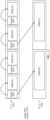
- k0 is determined based on a time unit in which a PDSCH is sent earliest on each CC. For example, as shown in FIG.
- the CC 1, the CC 2, and the CC 3 are co-scheduled by using the single DCI.
- the PDSCH scheduled on the CC 1 in the three CCs is sent earliest.
- the PDSCH on the CC 1 is determined based on an indication of k0, and indications of other CCs relative to k0 are offset values. If time units in which PDSCHs are sent on the CC 1 and the CC 2 are both earliest, a CC with a smaller index on the CC 1 and the CC 2 may be selected for determining.
- An advantage of determining k0 by using this method is that an offset is a value greater than or equal to 0.
- the base station may specify a CC, and determine the value of k0 based on the CC.
- a possibility that the offset has a negative value needs to be considered herein.
- a direction in which time increases may be a positive direction.
- the value of k0 may be determined based on the CC 2 in FIG. 10a .
- the indication of k0 is 1, and scheduling offset indications may respectively be -1, 0, and 2. This method is more flexible, but a case in which the offset may be less than 0 needs to be considered.
- the time domain resource assignment table shown in Table 6 may be configured by the base station for the terminal by using RRC signaling.
- the RRC signaling includes an information element PDSCH-TimeDomainResourceAllocation.
- the information element may be defined as follows:
- the time domain resource assignment table shown in Table 6 is applicable to both an indication of a downlink PDSCH and an indication of an uplink PUSCH.
- a difference lies in that in uplink DCI, an index value carried in a time domain resource assignment indication field is associated with k2, an SLIV, a mapping type, and a scheduling offset to k2.
- the base station may configure the time domain resource assignment table for the terminal by using an RRC configuration, and subsequently, in DCI, a specific configuration in the table may be selected by indicating an index value.
- the base station may configure the time domain resource assignment table by using an information element PUSCH-TimeDomainResourceAllocation in the RRC signaling.
- the information element PUSCH-TimeDomainResourceAllocation is defined as follows:
- the plurality of CCs scheduled by using the first DCI may share the time domain resource assignment field, so that bit overheads of the first DCI are reduced, and coverage performance is improved.
- k1 is a slot interval between receiving PDSCH data and feeding back a HARQ in a downlink, and a unit may be a time unit such as a slot.
- a slot An example in which a slot is used as the unit.
- a PDCCH carrying DCI is received in a slot 0.
- k0 indicated in a time domain resource assignment field in the DCI is equal to 4
- a PDSCH is received in a slot 4.
- information k1 carried in a PDSCH-to-HARQ feedback timing indicator field in the DCI is equal to 3
- a HARQ feedback is sent in a slot 7.
- the HARQ feedback may be carried in a PUCCH, and the HARQ feedback may be specifically an acknowledgment (acknowledgment, ACK), a negative acknowledgment (negative acknowledgment, NACK), or the like.
- k1 carried in the PDSCH-to-HARQ feedback timing indicator field in the first DCI when k1 carried in the PDSCH-to-HARQ feedback timing indicator field in the first DCI is configured to be shared by the plurality of CCs, k1 may indicate an offset value between a second reference location and a time unit corresponding to a HARQ, and the second reference location is determined based on a time unit corresponding to at least one of the plurality of CCs scheduled by using the first DCI.
- the method further includes: The UE determines, based on the second reference location and k1, a time unit corresponding to a HARQ in the plurality of CCs scheduled by using the first DCI.
- the second reference location may be a time unit corresponding to the first PDSCH in time domain of the PDSCHs on the plurality of CCs scheduled by using the first DCI, or a time unit corresponding to the last PDSCH in time domain of the PDSCHs on the plurality of CCs scheduled by using the first DCI.
- Any one of the plurality of CCs is offset relative to the second reference location by k1 time units, and the UE sends the HARQ at a same location in the plurality of CCs.
- the base station may send the first DCI on either of the two CCs.
- the base station may further send second DCI on the first CC.
- the first DCI is DCI that supports multi-carrier co-scheduling.
- the first DCI is single DCI.
- the second DCI is DCI that supports single-carrier scheduling.
- the second DCI is single DCI or legacy DCI.
- the legacy DCI may be DCI 1_1, DCI 0_1, DCI 1_0, DCI 0_0, or the like.
- the first DCI and the second DCI are sent in a same time unit.
- sending is performed by using a time unit N as a periodicity.
- the second DCI is sent in time units in intervals between different periodicities, and a value of N is determined based on the SCS of the first CC and the SCS of the second CC.
- the first DCI is single DCI.
- the UE needs to define a DCI processing capability.
- a CC 1 is referred to as a scheduling carrier
- an SCS of the CC 1 is 15 kHz
- a CC 2 is referred to as a scheduled carrier
- an SCS of the CC 2 is 30 kHz.
- the base station sends single DCI 1 and single DCI 2 on the CC 1, where PDSCHs 1 on the two CCs are co-scheduled by using the single DCI 1, and a PDSCH 2 on the CC 2 is scheduled by using the single DCI 2.
- the UE supports processing of the single DCI on the scheduling carrier.
- a capability of the UE to process a total quantity N of DCI on the scheduling carrier (namely, the CC 1) is related to an SCS. For example, if ⁇ scheduling carrier, scheduled carrier ⁇ corresponds to a combination of ⁇ 15 kHz, 30 kHz ⁇ or ⁇ 30 kHz, 60 kHz ⁇ , a value of N is 2.
- one PDSCH can be scheduled by using one piece of single DCI on the scheduling carrier.
- the single DCI 2 schedules one PDSCH on the single carrier.
- the legacy DCI is the foregoing second DCI.
- a CC 1 is referred to as a scheduling carrier
- a CC 2 is referred to as a scheduled carrier.
- a PDSCH 1 on the CC 1 and a PDSCH 1 on the CC 2 are scheduled by using single DCI 1 sent on the CC 1
- a PDSCH 2 on the CC2 is scheduled by using legacy DCI sent on the CC 1.
- the UE supports processing of two types of DCI on the scheduling carrier: the single DCI and the legacy DCI.
- a capability of the UE to process a total quantity N of DCI on the scheduling carrier (namely, the CC 1) is related to an SCS.
- scheduled carrier ⁇ corresponds to a combination of ⁇ 15 kHz, 30 kHz ⁇ or ⁇ 30 kHz, 60 kHz ⁇
- a value of N is 2.
- scheduled carrier ⁇ corresponds to a combination of ⁇ 15 kHz, 60 kHz ⁇
- a value of N is 4.
- the legacy DCI is the foregoing second DCI.
- a CC 1 is referred to as a scheduling carrier
- an SCS corresponding to the CC 1 is 30 kHz
- a CC 2 is referred to as a scheduled carrier
- an SCS corresponding to the CC 2 is 15 kHz.
- the base station sends single DCI on the CC 1, where a PDSCH 1 on the CC 1 and a PDSCH 1 on the CC 2 are scheduled by using the single DCI.
- the base station sends legacy DCI on the CC 1, where a PDSCH 2 on the CC 1 is scheduled by using the legacy DCI.
- the UE processes one piece of single DCI every N slots on the scheduling carrier, and only processing of the legacy DCI is supported in remaining slots.
- a periodicity of the single DCI may be referred to as N slots, and processing of the legacy DCI is supported in slots between different periodicities of the single DCI.
- a value of N may be related to an SCS configuration. For example, if ⁇ scheduling carrier, scheduled carrier ⁇ corresponds to a combination of ⁇ 30 kHz, 15 kHz ⁇ or ⁇ 60 kHz, 30 kHz ⁇ , the value of N is 2. If ⁇ scheduling carrier, scheduled carrier ⁇ corresponds to a combination of ⁇ 60 kHz, 15 kHz ⁇ , the value of N is 4.
- scheduling may be performed by using single DCI.
- a CC 1 is referred to as a scheduling carrier
- an SCS corresponding to the CC 1 is 30 kHz
- a CC 2 is referred to as a scheduled carrier
- an SCS corresponding to the CC 2 is 15 kHz.
- the base station sends single DCI 1 on the CC 1, where a PDSCH 1 on the CC 1 and a PDSCH 1 on the CC 2 are separately scheduled by using the single DCI 1.
- the base station sends single DCI 2 on the CC 1, where a PDSCH 2 on the CC1 is scheduled by using the single DCI 2.
- the single DCI 1 is the foregoing first DCI
- the single DCI 2 is the foregoing second DCI.
- the UE supports processing of N pieces of single DCI every N slots on the scheduling carrier.
- a value of N is mainly related to an SCS configuration. For example, if ⁇ scheduling carrier, scheduled carrier ⁇ corresponds to a combination of ⁇ 30 kHz, 15 kHz ⁇ or ⁇ 60 kHz, 30 kHz ⁇ , the value of N is 2. If ⁇ scheduling carrier, scheduled carrier ⁇ corresponds to a combination of ⁇ 60 kHz, 15 kHz ⁇ , the value of N is 4.
- N-1 pieces of single DCI support only a function of single-carrier scheduling.
- the foregoing mainly defines a capability of the UE to process DCI on a scheduling carrier or a scheduled carrier in different numerology configuration scenarios.
- the following focuses on a problem of how to design each field in single DCI to further reduce a DCI payload when a plurality of PDSCHs/PUSCHs on each carrier or CC can be co-scheduled by using the single DCI.
- the plurality of scheduled PDSCHs or PUSCHs may share some field information, to further reduce a payload size of the first DCI.
- information carried in any one of the following fields included in the first DCI may be shared by the plurality of data transmissions of the CC: frequency domain resource assignment, an MCS of a TB, a new data indicator of a TB, or an RV of a TB.
- the TB may include a TB 1, a TB 2, and/or the like.
- the information k0 indicated by the time domain resource assignment field may be a group of offset values k0, and the group of offset values k0 include a plurality of offset values k0.
- the group of offset values k0 are shared by the plurality of CCs, and the plurality of offset values k0 included in the group of offset values k0 are independently configured for a plurality of data transmissions scheduled on one CC by using the single DCI.
- the following uses an example in which the first DCI is single DCI for description.
- a quantity of PDSCHs/PUSCHs that can all be scheduled on one carrier by using the single DCI is no longer limited, and PDSCHs/PUSCHs on all carriers are scheduled and indicated by using the single DCI.
- This design may cause a size of the single DCI to increase exponentially, and affect a transmission coverage area.
- a plurality of PDSCHs/PUSCHs on a same CC scheduled by using the single DCI may further share some fields, to further reduce size overheads of the DCI. For example, a CC 1 and a CC 2 are scheduled by using the single DCI.
- Some fields in the single DCI may be shared by the CC 1 and the CC 2, or corresponding information is independently configured for the two CCs.
- An MCS field in the single DCI is used as an example. If the two CCs share the MCS field, information A carried in the MCS field may be shared by the CC 1 and the CC 2. If information carried in the MCS field is independently configured for the two CCs, an MCS field may separately carry information B1 and B2, where B1 corresponds to an MCS configuration on the CC 1, and B2 corresponds to an MCS configuration on the CC 2. Further, if the base station schedules a plurality of PDSCHs/PUSCHs on the CC 1, theoretically, each PDSCH/PUSCH corresponds to one MCS configuration. In this application, based on the following analysis and design, it is considered that some fields in single DCI are designed to be shared by a plurality of CCs, to reduce size overheads of the single DCI. Specific analysis is as follows:
- a CC 1 and a CC 2 are co-scheduled by using single DCI
- a numerology of the CC 1 is the same as a numerology of the CC 2
- SCSs of the CC 1 and the CC 2 are both 15 kHz.
- sizes of slots in all carriers are the same
- PDSCHs on different carriers are scheduled in a same transmission time interval (transmission time interval, TTI)
- TTI transmission time interval
- TTI transmission time interval
- HARQ information may be jointly fed back on two carriers, and DCI fields related to a PUCCH, for example, fields such as a PUCCH resource indicator, a HARQ timing indicator, and a TPC command, may also be shared.
- a value of k1 refers to a time interval between a PDSCH and a PUCCH
- a time unit corresponding to the first PDSCH in a cell for joint scheduling which is also referred to as a scheduling CC
- a scheduling CC may be used as a reference point
- a time unit corresponding to the last PDSCH in a cell for joint scheduling which is also referred to as a scheduling CC
- An example in which the time unit is a slot is used.
- a slot for transmitting a HARQ may be determined based on the reference point by offsetting k1 slots in a direction in which a slot number increases.
- adjacent slots are usually related. Therefore, fields such as frequency domain resource assignment, an MCS, a new data indicator, and an RV may be shared.
- a manner of scheduling a plurality of PDSCHs/PUSCHs on a plurality of carriers or CCs refer to FIG. 16 . Due to different time lengths on different carriers, if a larger quantity of PDSCHs are co-scheduled in a same TTI by using single DCI, a corresponding DCI size also increases exponentially, and a coverage capability is affected. Therefore, a co-scheduling mode in which a plurality of PDSCHs are scheduled in a plurality of TTIs in scenarios of different numerologies needs to be limited.
- a specific design is as follows: If a quantity of to-be-transmitted PDSCHs/PUSCHs is greater than a quantity of carriers or CCs, there are the following several implementations for a time-frequency domain assignment status of a quantity of PDSCHs/PUSCHs to be sent by the base station on a carrier co-scheduled by using the single DCI:
- a maximum quantity of PDSCHs/PUSCHs scheduled by using the single DCI is predefined.
- a maximum quantity of CCs that can be scheduled in frequency domain by using the single DCI is predefined, and a quantity of CCs that can all be scheduled in frequency domain is limited.
- a maximum quantity of slots that can be scheduled in time domain by using the single DCI is predefined, and a quantity of slots that can all be scheduled on one CC in time domain is limited.
- a time domain resource assignment field in a DCI field may be shared.
- a specific method for sharing a unified indication includes: It is agreed that a value of k0 is subject to a CC of a large subcarrier spacing, and a value of k0 of a small subcarrier spacing may be obtained based on a subcarrier spacing multiple relationship. Refer to the foregoing formula 1. Alternatively, it is agreed that a value of k0 is subject to a CC of a small subcarrier spacing, a new third field is designed in the DCI to indicate an offset relative to a location of k0 of the small subcarrier spacing, and a newly added field for transmitting each PDSCH is independently indicated.
- on different CCs means that a field in the single DCI is common, flexible, or independent on different CCs.
- "On a same CC” means that for a field in the single DCI, a plurality of PDSCHs/PUSCHs scheduled on a same CC by using the single DCI are common, flexible, independent, or the like.
- the field is independently configured on different CCs, but is shared on a same CC.
- PDSCH transmission on a CC 1 and a CC 2 is scheduled by using the single DCI.
- the MSC field includes information A and information B, where the information A corresponds to the CC 1, and the information B corresponds to the CC 2. Further, if a plurality of PDSCHs are scheduled on the CC 2 by using the single DCI, the plurality of PDSCHs on the CC 2 share the information B.
- scheduling of a plurality of PDSCHs/PUSCHs on a plurality of carriers or CCs is implemented by using the single DCI, and DCI fields are designed for sharing when a plurality of PDSCHs/PUSCHs are sent on a same carrier or CC and different carriers or CCs, so that payload overheads of the single DCI are reduced.
- the base station and the terminal include corresponding hardware structures and/or software modules for performing the functions.
- a person skilled in the art should be easily aware that, with reference with units and method steps in the examples described in this application, this application can be implemented by hardware or a combination of hardware and computer software. Whether a function is performed by hardware or hardware driven by computer software depends on particular application scenarios and design constraint conditions of the technical solutions.
- FIG. 17 and FIG. 18 are diagrams of structures of possible communication apparatuses according to this application. These communication apparatuses may be configured to implement functions of the terminal or the base station in the foregoing methods, and therefore can also implement beneficial effect of the foregoing methods.
- the communication apparatus may be one of the terminals 120a to 120j shown in FIG. 1 , or may be the base station 110a or 110b shown in FIG. 1 , or may be a module (for example, a chip) used in the terminal or the base station.
- a communication apparatus 1700 includes a processing unit 1710 and a transceiver unit 1720.
- the communication apparatus 1700 is configured to implement the functions of the base station in the foregoing method embodiments.
- the transceiver unit 1720 is configured to send first downlink control information DCI to a terminal.
- the first DCI is for scheduling transmission of a plurality of component carriers CCs, the first DCI includes a first field, and information carried in the first field is shared by the plurality of CCs.
- information k0 carried in the first field is configured to be shared by the plurality of CCs, k0 indicates an offset value between a first reference location and a time unit corresponding to a physical downlink shared channel PDSCH, and the first reference location is determined based on a time unit corresponding to the first DCI.
- the processing unit 1710 is configured to determine the first DCI.
- the transceiver unit 1720 is configured to receive first downlink control information DCI from a network device.
- the first DCI is for scheduling transmission of a plurality of component carriers CCs, the first DCI includes a first field, and information carried in the first field is shared by the plurality of CCs.
- information k0 carried in the first field is configured to be shared by the plurality of CCs, k0 indicates an offset value between a first reference location and a time unit corresponding to a physical downlink shared channel PDSCH, and the first reference location is determined based on a time unit corresponding to the first DCI.
- the processing unit 1710 is configured to process the first DCI.
- processing unit 1710 and the transceiver unit 1720 directly refer to related descriptions in the foregoing method embodiments. Details are not described herein.
- a communication apparatus 1800 includes a processor 1810 and an interface circuit 1820.
- the processor 1810 and the interface circuit 1820 are coupled to each other.
- the interface circuit 1820 may be a transceiver or an input/output interface.
- the communication apparatus 1800 may further include a memory 1830, configured to store instructions executed by the processor 1810, or input data required by the processor 1810 to run the instructions, or data generated after the processor 1810 runs the instructions.
- the processor 1810 is configured to implement the functions of the processing unit 1710
- the interface circuit 1820 is configured to implement the functions of the transceiver unit 1720.
- the module in the base station implements the functions of the base station in the foregoing method.
- the module in the base station receives information from another module (for example, a radio frequency module or an antenna) in the base station, where the information is sent by a terminal device to the base station; or the module in the base station sends information to another module (for example, a radio frequency module or an antenna) in the base station, where the information is sent by the base station to a terminal device.
- the module in the base station herein may be a baseband chip in the base station, or may be a DU or another module.
- the DU herein may be a DU in an open radio access network (open radio access network, O-RAN) architecture.
- the terminal chip implements a function of the terminal in the foregoing method embodiments.
- the chip in the terminal receives information from another module (for example, a radio frequency module or an antenna) in the terminal, where the information is sent by a base station to the terminal; or the chip in the terminal sends information to another module (for example, a radio frequency module or an antenna) in the terminal, where the information is sent by the terminal to a base station.
- another module for example, a radio frequency module or an antenna
- the processor in this application may be a central processing unit (central processing unit, CPU), or may be another general-purpose processor, a digital signal processor (digital signal processor, DSP), or an application-specific integrated circuit (application-specific integrated circuit, ASIC), a field programmable gate array (field programmable gate array, FPGA) or another programmable logic device, a transistor logic device, a hardware component, or any combination thereof.
- the general purpose processor may be a microprocessor or any regular processor or the like.
- the memory in this application may be a random access memory, a flash memory, a read-only memory, a programmable read-only memory, an erasable programmable read-only memory, an electrically erasable programmable read-only memory, a register, a hard disk, a removable hard disk, a CD-ROM, or a storage medium of any other form well-known in the art.
- a storage medium is coupled to a processor, so that the processor can read information from the storage medium and write information into the storage medium.
- the storage medium may alternatively be a component of the processor.
- the processor and the storage medium may be disposed in an ASIC.
- the ASIC may be located in a base station or a terminal device.
- the processor and the storage medium may alternatively exist in a base station or a terminal device as discrete components.
- Methods in this application may be wholly or partially implemented by software, hardware, firmware, or any combination thereof.
- software When software is used to implement embodiments, all or a part of embodiments may be implemented in a form of a computer program product.
- the computer program product includes one or more computer programs or instructions. When the computer programs or instructions are loaded and executed on the computer, the procedure or functions according to this application are completely or partially generated.
- the computer may be a general-purpose computer, a dedicated computer, a computer network, a network device, user equipment, a core network device, OAM, or another programmable apparatus.
- the computer program or instructions may be stored in a computer-readable storage medium, or may be transmitted from a computer-readable storage medium to another computer-readable storage medium.
- the computer program or instructions may be transmitted from a website, computer, server, or data center to another website, computer, server, or data center in a wired or wireless manner.
- the computer-readable storage medium may be any usable medium that can be accessed by the computer, or a data storage device, for example, a server or a data center, integrating one or more usable media.
- the usable medium may be a magnetic medium, for example, a floppy disk, a hard disk, or a magnetic tape; or may be an optical medium, for example, a digital video disc; or may be a semiconductor medium, for example, a solid-state drive.
- the computer-readable storage medium may be a volatile or non-volatile storage medium, or may include two types of storage media: a volatile storage medium and a non-volatile storage medium.
- At least one means one or more, and a plurality of means two or more.
- “And/or” describes an association relationship between associated objects, and represents that three relationships may exist.
- a and/or B may represent the following cases: A exists alone, both A and B exist, and B exists alone, where A and B may be singular or plural.
- the character “/” indicates an "or” relationship between the associated objects.
- the character “/” indicates a "division” relationship between the associated objects.
- “Including at least one of A, B, or C” may indicate: including A; including B; including C; including A and B; including A and C; including B and C; and including A, B, and C.
Landscapes
- Engineering & Computer Science (AREA)
- Signal Processing (AREA)
- Computer Networks & Wireless Communication (AREA)
- Mobile Radio Communication Systems (AREA)
Applications Claiming Priority (3)
| Application Number | Priority Date | Filing Date | Title |
|---|---|---|---|
| CN202210342432.5A CN114885431A (zh) | 2022-03-31 | 2022-03-31 | 一种通信方法及装置 |
| CN202210964130.1A CN116939850A (zh) | 2022-03-31 | 2022-08-11 | 一种通信方法及装置 |
| PCT/CN2023/085053 WO2023186005A1 (zh) | 2022-03-31 | 2023-03-30 | 一种通信方法及装置 |
Publications (2)
| Publication Number | Publication Date |
|---|---|
| EP4492900A1 true EP4492900A1 (de) | 2025-01-15 |
| EP4492900A4 EP4492900A4 (de) | 2025-07-16 |
Family
ID=88199381
Family Applications (1)
| Application Number | Title | Priority Date | Filing Date |
|---|---|---|---|
| EP23778370.9A Pending EP4492900A4 (de) | 2022-03-31 | 2023-03-30 | Kommunikationsverfahren und -vorrichtung |
Country Status (3)
| Country | Link |
|---|---|
| US (1) | US20250039899A1 (de) |
| EP (1) | EP4492900A4 (de) |
| WO (1) | WO2023186005A1 (de) |
Families Citing this family (4)
| Publication number | Priority date | Publication date | Assignee | Title |
|---|---|---|---|---|
| US20230345502A1 (en) * | 2022-04-21 | 2023-10-26 | Qualcomm Incorporated | Carrier indicator field mapping |
| US20240057096A1 (en) * | 2022-08-10 | 2024-02-15 | Qualcomm Incorporated | Techniques for communicating multi-cell downlink control information |
| CN120050013A (zh) * | 2023-11-27 | 2025-05-27 | 上海华为技术有限公司 | Rrc信令传输的方法和通信装置 |
| CN120935720A (zh) * | 2024-05-10 | 2025-11-11 | 大唐移动通信设备有限公司 | 信息处理、传输方法、装置及设备 |
Family Cites Families (5)
| Publication number | Priority date | Publication date | Assignee | Title |
|---|---|---|---|---|
| CN120166548A (zh) * | 2019-03-29 | 2025-06-17 | 中兴通讯股份有限公司 | 下行控制信息传输方法及装置 |
| WO2020204561A1 (ko) * | 2019-03-29 | 2020-10-08 | 엘지전자 주식회사 | 무선 통신 시스템에서 무선 신호 송수신 방법 및 장치 |
| CN113473635B (zh) * | 2020-03-31 | 2026-04-21 | 英特尔公司 | 用于nr操作的两小区调度 |
| WO2021224965A1 (ja) * | 2020-05-07 | 2021-11-11 | 株式会社Nttドコモ | 端末、無線通信方法及び基地局 |
| CN114885431A (zh) * | 2022-03-31 | 2022-08-09 | 华为技术有限公司 | 一种通信方法及装置 |
-
2023
- 2023-03-30 WO PCT/CN2023/085053 patent/WO2023186005A1/zh not_active Ceased
- 2023-03-30 EP EP23778370.9A patent/EP4492900A4/de active Pending
-
2024
- 2024-09-27 US US18/899,415 patent/US20250039899A1/en active Pending
Also Published As
| Publication number | Publication date |
|---|---|
| US20250039899A1 (en) | 2025-01-30 |
| WO2023186005A1 (zh) | 2023-10-05 |
| EP4492900A4 (de) | 2025-07-16 |
Similar Documents
| Publication | Publication Date | Title |
|---|---|---|
| US12308900B2 (en) | State information for network cooperative communication | |
| US11818778B2 (en) | Method and apparatus for transmitting or receiving data and control information in wireless communication system | |
| US11582004B2 (en) | Method and apparatus for reporting channel state information in wireless communication systems | |
| US12058718B2 (en) | Method and apparatus for reporting channel state information for network cooperative communication | |
| US20220086894A1 (en) | Multi-cell scheduling with reduced control overhead | |
| KR102935690B1 (ko) | 무선 통신 시스템에서 제어 및 데이터 채널 송수신 방법 및 장치 | |
| EP4072057A1 (de) | Verfahren und gerät zum senden oder empfangen eines referenzsignals in einem drahtlosen kommunikationssystem | |
| US20210314100A1 (en) | Method and device for transmitting or receiving harq-ack feedback in wireless communication system | |
| WO2022022286A2 (en) | Method and apparatus for transmitting csi report | |
| EP4492900A1 (de) | Kommunikationsverfahren und -vorrichtung | |
| US20210250944A1 (en) | Method and apparatus for transmitting control information for network cooperative communication | |
| KR102456001B1 (ko) | 무선 통신 시스템에서 상향링크 캐리어를 통해 데이터를 송수신하기 위한 방법 및 장치 | |
| EP4072055A1 (de) | Verfahren und vorrichtung zum senden oder empfangen eines uplink-steuer- und datenkanals in einem drahtlosen kommunikationssystem | |
| EP4498614A1 (de) | Verfahren und vorrichtung zum senden oder empfangen von kanalstatusinformationen in einem kommunikationssystem | |
| US11665677B2 (en) | Method and apparatus for operating bandwidth part in wireless communication system | |
| US20230239117A1 (en) | Method and apparatus for determining channel access procedure in wireless communication system | |
| US20230318761A1 (en) | Method and device for transmitting/receiving control information in wireless cooperative communication system | |
| US11647553B2 (en) | Method and apparatus for performing dual connectivity for UEs in wireless communication system | |
| US12368537B2 (en) | Method and apparatus for transmitting/receiving HARQ-ACK feedback for network cooperative communication | |
| US20230224824A1 (en) | Control information transmission method and device for network cooperative communication of wireless communication system | |
| US11805525B2 (en) | Method and apparatus for determining of transmission resources for uplink channels of use for dual connectivity in wireless communication system | |
| US20220116158A1 (en) | Method and apparatus for transmission of harq-ack in wireless communication system | |
| US20220029737A1 (en) | Method and apparatus for repetition-based data transmission for network cooperative communication | |
| CN116939850A (zh) | 一种通信方法及装置 | |
| US11818081B2 (en) | Method and device for transmitting uplink channel, by terminal, for dual connectivity in wireless communication system |
Legal Events
| Date | Code | Title | Description |
|---|---|---|---|
| STAA | Information on the status of an ep patent application or granted ep patent |
Free format text: STATUS: THE INTERNATIONAL PUBLICATION HAS BEEN MADE |
|
| PUAI | Public reference made under article 153(3) epc to a published international application that has entered the european phase |
Free format text: ORIGINAL CODE: 0009012 |
|
| STAA | Information on the status of an ep patent application or granted ep patent |
Free format text: STATUS: REQUEST FOR EXAMINATION WAS MADE |
|
| 17P | Request for examination filed |
Effective date: 20241008 |
|
| AK | Designated contracting states |
Kind code of ref document: A1 Designated state(s): AL AT BE BG CH CY CZ DE DK EE ES FI FR GB GR HR HU IE IS IT LI LT LU LV MC ME MK MT NL NO PL PT RO RS SE SI SK SM TR |
|
| DAV | Request for validation of the european patent (deleted) | ||
| DAX | Request for extension of the european patent (deleted) | ||
| A4 | Supplementary search report drawn up and despatched |
Effective date: 20250617 |
|
| RIC1 | Information provided on ipc code assigned before grant |
Ipc: H04W 72/12 20230101AFI20250611BHEP Ipc: H04L 5/00 20060101ALI20250611BHEP |