EP4493437B1 - Systèmes et méthodes d'évaluation des remorques - Google Patents
Systèmes et méthodes d'évaluation des remorques Download PDFInfo
- Publication number
- EP4493437B1 EP4493437B1 EP24713830.8A EP24713830A EP4493437B1 EP 4493437 B1 EP4493437 B1 EP 4493437B1 EP 24713830 A EP24713830 A EP 24713830A EP 4493437 B1 EP4493437 B1 EP 4493437B1
- Authority
- EP
- European Patent Office
- Prior art keywords
- trailer
- vehicle
- control system
- air brakes
- measured
- Prior art date
- Legal status (The legal status is an assumption and is not a legal conclusion. Google has not performed a legal analysis and makes no representation as to the accuracy of the status listed.)
- Active
Links
Images


Classifications
-
- B—PERFORMING OPERATIONS; TRANSPORTING
- B60—VEHICLES IN GENERAL
- B60T—VEHICLE BRAKE CONTROL SYSTEMS OR PARTS THEREOF; BRAKE CONTROL SYSTEMS OR PARTS THEREOF, IN GENERAL; ARRANGEMENT OF BRAKING ELEMENTS ON VEHICLES IN GENERAL; PORTABLE DEVICES FOR PREVENTING UNWANTED MOVEMENT OF VEHICLES; VEHICLE MODIFICATIONS TO FACILITATE COOLING OF BRAKES
- B60T7/00—Brake-action initiating means
- B60T7/12—Brake-action initiating means for automatic initiation; for initiation not subject to will of driver or passenger
- B60T7/20—Brake-action initiating means for automatic initiation; for initiation not subject to will of driver or passenger specially for trailers, e.g. in case of uncoupling of or overrunning by trailer
-
- B—PERFORMING OPERATIONS; TRANSPORTING
- B60—VEHICLES IN GENERAL
- B60T—VEHICLE BRAKE CONTROL SYSTEMS OR PARTS THEREOF; BRAKE CONTROL SYSTEMS OR PARTS THEREOF, IN GENERAL; ARRANGEMENT OF BRAKING ELEMENTS ON VEHICLES IN GENERAL; PORTABLE DEVICES FOR PREVENTING UNWANTED MOVEMENT OF VEHICLES; VEHICLE MODIFICATIONS TO FACILITATE COOLING OF BRAKES
- B60T8/00—Arrangements for adjusting wheel-braking force to meet varying vehicular or ground-surface conditions, e.g. limiting or varying distribution of braking force
- B60T8/17—Using electrical or electronic regulation means to control braking
- B60T8/1701—Braking or traction control means specially adapted for particular types of vehicles
- B60T8/1708—Braking or traction control means specially adapted for particular types of vehicles for lorries or tractor-trailer combinations
-
- B—PERFORMING OPERATIONS; TRANSPORTING
- B60—VEHICLES IN GENERAL
- B60T—VEHICLE BRAKE CONTROL SYSTEMS OR PARTS THEREOF; BRAKE CONTROL SYSTEMS OR PARTS THEREOF, IN GENERAL; ARRANGEMENT OF BRAKING ELEMENTS ON VEHICLES IN GENERAL; PORTABLE DEVICES FOR PREVENTING UNWANTED MOVEMENT OF VEHICLES; VEHICLE MODIFICATIONS TO FACILITATE COOLING OF BRAKES
- B60T8/00—Arrangements for adjusting wheel-braking force to meet varying vehicular or ground-surface conditions, e.g. limiting or varying distribution of braking force
- B60T8/17—Using electrical or electronic regulation means to control braking
- B60T8/171—Detecting parameters used in the regulation; Measuring values used in the regulation
-
- B—PERFORMING OPERATIONS; TRANSPORTING
- B60—VEHICLES IN GENERAL
- B60W—CONJOINT CONTROL OF VEHICLE SUB-UNITS OF DIFFERENT TYPE OR DIFFERENT FUNCTION; CONTROL SYSTEMS SPECIALLY ADAPTED FOR HYBRID VEHICLES; ROAD VEHICLE DRIVE CONTROL SYSTEMS FOR PURPOSES NOT RELATED TO THE CONTROL OF A PARTICULAR SUB-UNIT
- B60W40/00—Estimation or calculation of non-directly measurable driving parameters for road vehicle drive control systems not related to the control of a particular sub unit, e.g. by using mathematical models
- B60W40/10—Estimation or calculation of non-directly measurable driving parameters for road vehicle drive control systems not related to the control of a particular sub unit, e.g. by using mathematical models related to vehicle motion
- B60W40/1005—Driving resistance
-
- B—PERFORMING OPERATIONS; TRANSPORTING
- B60—VEHICLES IN GENERAL
- B60T—VEHICLE BRAKE CONTROL SYSTEMS OR PARTS THEREOF; BRAKE CONTROL SYSTEMS OR PARTS THEREOF, IN GENERAL; ARRANGEMENT OF BRAKING ELEMENTS ON VEHICLES IN GENERAL; PORTABLE DEVICES FOR PREVENTING UNWANTED MOVEMENT OF VEHICLES; VEHICLE MODIFICATIONS TO FACILITATE COOLING OF BRAKES
- B60T2210/00—Detection or estimation of road or environment conditions; Detection or estimation of road shapes
- B60T2210/30—Environment conditions or position therewithin
-
- B—PERFORMING OPERATIONS; TRANSPORTING
- B60—VEHICLES IN GENERAL
- B60W—CONJOINT CONTROL OF VEHICLE SUB-UNITS OF DIFFERENT TYPE OR DIFFERENT FUNCTION; CONTROL SYSTEMS SPECIALLY ADAPTED FOR HYBRID VEHICLES; ROAD VEHICLE DRIVE CONTROL SYSTEMS FOR PURPOSES NOT RELATED TO THE CONTROL OF A PARTICULAR SUB-UNIT
- B60W2300/00—Indexing codes relating to the type of vehicle
- B60W2300/12—Trucks; Load vehicles
Definitions
- the present disclosure relates generally to tractor-trailer systems, and more particularly, to assessing the condition of one or more features of a semi-trailer system, for example, condition and/or operation of the pneumatic brakes of the trailer.
- An 18-wheeler or tractor-trailer truck includes a semi-trailer (also referred to herein as “trailer”) releasably coupled to a tractor (also referred to herein as "truck”).
- a semi-trailer also referred to herein as "trailer”
- tractor also referred to herein as "truck”
- the trailer is often disconnected from the truck, for example, for cargo loading, cargo unloading, storage, or changing between trucks.
- the trailer may sit idle for an extended period of time (e.g., days or weeks) until it is connected to another truck for transport from a parked location (e.g., within a yard or lot) or to a local vehicle (e.g., hostler) for transport around a yard or lot.
- a parked location e.g., within a yard or lot
- a local vehicle e.g., hostler
- US 2021/0370922 A1 proposes a system and method to address jackknifing in autonomous vehicles.
- US 2016/0257341 A1 proposes a trailer backup assist system.
- the invention provides a control system as set out in claim 1, an autonomous vehicle as set out in claim 7, and a method as set out in claim 9.
- Embodiments of the disclosed subject matter provide systems and methods of assessing a trailer prior to or during movement by a towing vehicle (e.g., a prime mover vehicle, such as a tractor or hostler).
- the assessment of the trailer includes determining brake actuation levels (e.g., air pressure) from the towing vehicle to the trailer to provide a desired braking force.
- brake actuation levels can include building a model based at least in part on measured data and/or compiling a table based at least in part on measured data that is used as input to a feed forward control algorithm.
- the assessment of the trailer can include determining the health or integrity of emergency brakes of the trailer.
- the assessment of the trailer can include evaluating features (e.g., collectively) that impact kinematics of the trailer, for example, wear condition of wheel bearings, tire inflation, trailer drag, etc.
- the data measured for assessing the trailer can include (i) static resistance of the trailer, (ii) rolling resistance of the trailer, (iii) acceleration (e.g., deceleration) rate of the trailer, (iv) forces applied between the trailer and the towing vehicle, (v) weight of the trailer, (vi) power applied, torque applied, and/or energy used by motor(s) of the towing vehicle, or (vii) any combination of (i)-(vi).
- a control system can comprise one or more processors and one or more non-transitory computer-readable media storing computer-readable instructions.
- the computer-readable instructions can cause the one or more processors to (a) measure static resistance and rolling resistance of a trailer without application of any braking force by service air brakes and emergency air brakes of the trailer; (b) apply an actuation level to the service air brakes of the trailer while releasing the emergency air brakes of the trailer; (c) measure static resistance, rolling resistance, and/or acceleration rate of the trailer during (b); and (d) determine an operational model for actuation of the service air brakes of the trailer based at least in part on the measured static resistances, rolling resistances, and/or acceleration rate.
- an autonomous vehicle can comprise a fifth-wheel coupling, a drive-by-wire kit, one or more motors, one or more sensors, and a vehicle control system.
- the fifth-wheel coupling can be configured to be coupled to a trailer.
- the one or more sensors can be configured to detect features in an environment surrounding the vehicle, forces applied to the vehicle, and/or forces applied to the trailer.
- the vehicle control system can be operatively coupled to the drive-by-wire kit, the one or more motors, and the one or more sensors.
- the vehicle control system can comprise one or more processors and one or more non-transitory computer-readable media storing computer-readable instructions.
- the computer-readable instructions can cause the one or more processors to (a) apply an actuation level to the service air brakes of the trailer while releasing the emergency air brakes of the trailer; (b) measure static resistance, rolling resistance, and/or acceleration rate of the trailer during (a); and (c) determine an operational model for actuation of the service air brakes of the trailer based at least in part on the static resistances, rolling resistances, and/or acceleration rate measured in (b).
- a method can comprise (a) applying an actuation level to service air brakes of a trailer while releasing emergency air brakes of the trailer.
- the method can further comprise (b) measuring static resistance, rolling resistance, and/or acceleration rate of the trailer during (a).
- the method can also comprise (c) repeating (a) and (b) one or more times at different actuation levels.
- the method can further comprise (d) determining an operational model for actuation of the service air brakes of the trailer based at least in part on the measured static resistances, rolling resistances, and/or acceleration rates.
- the towing vehicle is an autonomous truck or vehicle, for example, a yard hostler, such as but not limited to those vehicles disclosed in International Publication No. WO 2023/212044, published November 2, 2023 , and entitled "Autonomous Gladhands Coupling Systems, Devices, and Methods,".
- the assessment of the trailer can be in situ, for example, during movement and/or attempted movement of the trailer by the towing vehicle.
- FIG. 1A illustrates a tractor-trailer system 100 that includes a towing vehicle 102 (an autonomous or semi-autonomous vehicle) connected to a trailer 112 via fifth-wheel coupling 108.
- a towing vehicle 102 an autonomous or semi-autonomous vehicle
- the vehicle 102 can have one or more gladhand couplers or connectors 106 that connect, mate, and/or interface with a corresponding gladhand receptacle 116 of the trailer 112, for example, to allow pressurized air from the vehicle 102 to pressurize the pneumatic supply lines of the trailer braking system and/or to control engagement of the trailer service brakes (or disengagement of the trailer emergency brakes).
- operation of the vehicle 102 and/or operation of the brakes of the trailer 112 can be controlled by a control system 104 of the vehicle 102.
- the control system 104 can be configured to perform an assessment of the trailer 112.
- motive features e.g., operability of the trailer brakes, regulation of the service brakes, condition of ball bearings 118, inflation of tires 114, etc.
- the control system 104 is mounted on or located within the vehicle 102.
- control system 104 can be located outside of vehicle 102, for example, one or more control modules remote from the vehicle 102 (e.g., a centralized control system for a yard in which the vehicle 102 operates).
- the vehicle 102 (or the control system thereof) can communicate with other vehicles and/or a centralized control system, for example, using antenna 120.
- FIG. 1B illustrates another tractor-trailer system 150 that employs a remote control unit 152 for controlling operation of the brakes of the trailer 112.
- the remote control unit 152 can have one or more gladhand couplers or connectors 156 that connect, mate, and/or interface with a corresponding gladhand receptacle116 of the trailer 112.
- control system 104 can control operation of the remote control unit 152, for example, via wireless signal (e.g., via radio, ultra-wideband (UWB), Bluetooth, Wi-Fi, cellular, optical, or any other wireless communication protocol) from antenna 120 to antenna 154 (e.g., receiver or transceiver) of the remote control unit 152.
- wireless signal e.g., via radio, ultra-wideband (UWB), Bluetooth, Wi-Fi, cellular, optical, or any other wireless communication protocol
- antenna 154 e.g., receiver or transceiver
- the remote control until 152 and the control system 104 can be capable of two-way communication, for example, such that the control system 104 can receive status information (e.g., parking brake engaged versus disengaged, braking system pressure, charge status or power level of the remote unit 152, location of the remote unit 152, trailer braking system type, etc.) from the remote unit 152.
- the remote control unit 152 can include multiple connections to pressurize the trailer braking system to disengage the parking brake, thereby allowing the trailer 112 to be moved, and to control application of the service brakes.
- the connection to the service braking line can be used by the control system 104 to provide supplemental braking via the trailer 112 during movement by vehicle 102.
- the assessment of the trailer can include testing operation of the brakes of the trailer, for example, the service brakes, the emergency brakes, or both.
- the vehicle coupled to the trailer can independently control the brakes of the trailer (separate from or in addition to the brakes of the vehicle) as the vehicle is towing (or attempting to tow) the trailer in order to determine if the brakes are operational.
- the assessment of the trailer can include determining regulation of the brakes for the trailer, for example, the service brakes, the emergency brakes, or both.
- the vehicle coupled to the trailer can control the brakes of the trailer to apply a predetermined or desired braking force, and the vehicle can measure the resulting braking force.
- the assessment of the trailer can include evaluating another motive feature of the trailer, for example, a wear condition of one or more ball bearings, an inflation level of one or more tires, and/or any other feature that would affect drivability of the trailer.
- the assessment of the trailer can be based on a weight of the trailer.
- the weight of the trailer can be calculated or at least estimated, for example, based on imaging (e.g., visual imagery, LIDAR, etc.), mechanics calculations (e.g., based on measured acceleration using Newton's second law of motion), or any other methodology.
- the weight of the trailer can be measured, for example, via a truck scale.
- the weight of the trailer may be known (e.g., from a previous measurement or calculation), for example, stored in a database accessible for use in the assessment.
- the assessment of the trailer can be based on a measured force between the trailer and the coupled vehicle.
- the assessment can include comparing a tractive effort of the vehicle with different actuation levels (e.g., applied pressured) the trailer service brakes.
- one or more sensors can be used to measure the force applied by the vehicle to the trailer.
- the measured force can be determined based on motor operation of the vehicle (e.g., power or current input to the motor, revolutions per minute (RPM) of the motor, power or torque output by the motor, energy consumed by the motor, etc.) during towing or attempted towing of the trailer by the vehicle.
- motor operation of the vehicle e.g., power or current input to the motor, revolutions per minute (RPM) of the motor, power or torque output by the motor, energy consumed by the motor, etc.
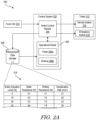
- FIG. 2A shows a simplified configuration 200 of components for assessment of a trailer.
- the configuration 200 includes a control system 202 and a trailer 212 (e.g., a trailer undergoing assessment and/or towing).
- the control system 202 is part of (e.g., integrated or communicating with a vehicle control system) or at least mounted on or in a towing vehicle (e.g., a prime mover vehicle, such as a truck or hosteler).
- the control system 202 is remote from and in communication with (e.g., wireless communication ) the towing vehicle, for example, a yard control system, a central fleet control system, or any other type of remote station.
- control system 202 is in communication (e.g., wired or wireless) with a data storage device 208 (e.g., database).
- a data storage device 208 e.g., database
- the data storage device 208 can be part of or at least mounted on or in the towing vehicle.
- the data storage device 208 can be remote from the control system 202 and/or the towing vehicle.
- the data storage device 208 stores information obtained during assessment of the trailer 212.
- the data storage device 208 can store other information, such as but not limited to rules or protocols for performing an assessment of the trailer, other information regarding trailer 212 (e.g., not otherwise obtained by the assessment, such as trailer weight, contents, identifier, etc.), information regarding other trailers (e.g., obtained by control system 202 or other control systems by a prior assessment), rules of the road (e.g., when data storage device 208 is shared with the vehicle control system), docking locations, road or travel path network information, etc.
- other information regarding trailer 212 e.g., not otherwise obtained by the assessment, such as trailer weight, contents, identifier, etc.
- information regarding other trailers e.g., obtained by control system 202 or other control systems by a prior assessment
- rules of the road e.g., when data storage device 208 is shared with the vehicle control system
- docking locations e.g., when data storage device 208 is shared with the vehicle control system
- road or travel path network information etc.
- the control system 202 is in communication (e.g., wired or wireless) with a source of force information 210.
- the force information source 210 can be part of or at least mounted on or in the towing vehicle.
- the force information source 210 can be a force sensor 222 mounted on or integrated with the fifth-wheel coupling 108 that measures the force between the towing vehicle 102 and the trailer 112, as shown by the sensor configuration 220 of FIG. 2B .
- FIG. 2B In the illustrated example of FIG.
- the force sensor 222 can be a strain gauge; however, other force measurement sensors (and corresponding configurations) are also possible according to one or more contemplated embodiments, such as but not limited to load cells, accelerometers, pressure sensors, torque sensors, etc.
- the force information source 210 can be part of the existing vehicle infrastructure, for example, the vehicle control system or other component providing information regarding motor performance (e.g., power or torque applied by the motor, revolutions per minute of the motor, energy used by the motor, power or current applied to an electric motor, etc.) that can be used as a proxy for forces between the towing vehicle and the trailer.
- the force information source 210 can be remote from the towing vehicle, for example, a force sensor that is mounted on or integrated with the trailer (e.g., the kingpin of the trailer).
- the force information source 210 can be used to estimate or determine other characteristics of the trailer 212, for example, a weight of the trailer.
- the control system 202 includes a brake control module 204 that controls actuation of the service air brakes 214 and the emergency air brakes 216 of the trailer, for example, by applying air pressure to the respective trailer brake lines.
- air pressure is supplied from the towing vehicle via pneumatic lines connected to respective gladhand receptacles on the trailer by gladhand couplings, and the brake control module 204 (whether located on or remote from the towing vehicle) can control application of the air pressure to provide desired trailer braking (e.g., a particular braking force for the service air brakes, complete release of the emergency air brakes, etc.).
- air pressure is supplied via one or more remote control units connected to the trailer gladhand receptacles, and the brake control module 204 (whether located on or remote from the towing vehicle) can send command signals to the remote control unit(s) to generate and/or apply air pressure to provide desired trailer braking.
- the control system 202 further includes an operational model 206, which can include a model of or information on trailer kinematics 206a and a model of or information on trailer braking 206b.
- the trailer kinematic model/information 206a can capture or be based on trailer wheel bearing conditions, trailer tire inflation, trailer drag, and/or any other trailer feature that may affect its movement.
- the trailer braking model/information 206b can capture or be based on trailer braking at different actuation levels (e.g., air pressure applied).
- the operational model 206 can be a control algorithm (e.g., a feed forward control algorithm) that takes in previously determined trailer assessment data (e.g., via data storage device 208) and outputs an actuation level (e.g., to brake control module 204, for use in controlling trailer brakes 214, 216) to achieve a desired braking performance.
- a control algorithm e.g., a feed forward control algorithm
- the control system 202 can determine that a desired braking performance is needed for the trailer 212 (e.g., to stop within a certain distance, to reduce to a particular speed, etc.), and brake control module 204 can interface with the operational model 206 to select an appropriate brake actuation level to achieve the desired performance.
- the selected brake actuation level can then be commanded (e.g., sent or applied) to the service brakes 214 of the trailer 212 via the brake control module 204.
- the determination of desired braking performance and selection/command of brake actuation level can be repeated on a continuous or periodic basis, for example, to account for dynamic or changing operating conditions (e.g., a new obstacle requiring greater braking, changes in road conditions, changes in motor performance, etc.).
- the previously determined trailer assessment data can be in the form of data structure, such as data table 218.
- the data table 218 can include data measured (e.g., by the force information source 210, by the control system 202, by sensors of the towing vehicle or trailer, or by any other system) during movement or attempted movement of the trailer 212 at different brake actuation levels (e.g., as a percentage of maximum pressure available in the air braking system, for example, 100-120 psi).
- the static resistance of the trailer e.g., the amount of force needed to initiate movement of the trailer when at rest
- the rolling resistance of the trailer e.g., the amount of force needed to maintain movement of the trailer
- the acceleration rate e.g., either positive (increasing speed) or negative (decreasing speed
- other data can be measured (simultaneously or at a different time) and included in data table 218 as well.
- the other data can include but is not limited to measured force between the trailer and the towing vehicle (e.g., during acceleration rate measurements), force or power applied by the towing vehicle (e.g., during static and/or rolling resistance measurements), etc.
- the static resistance can be measured by slowly increasing the speed or power of the towing vehicle until the trailer begins to move, and/or the rolling resistance of the trailer can be measured while the trailer is moved along a straight, flat roadway at constant speed.
- the difference between the rolling resistance and the static resistance e.g., at zero brake actuation level
- trailer kinematics e.g., trailer wheel bearing conditions, trailer tire inflation, trailer drag, and/or any other trailer feature that may affect its movement
- the acceleration rate can be measured by moving the trailer 212 at a constant speed, applying a brake actuation level to the trailer brakes, and measuring a time and/or distance until the trailer 212 stops (or reaches a predetermined slower speed).
- the acceleration rate can provide information regarding trailer braking, which can serve as a basis for trailer braking model/information 206b.
- assessments can be performed at one or more different brake actuation levels (e.g., 0%, 50%, and 100%), and the results extrapolated (e.g., interpolated) for other brake actuation levels.
- data table 218 shows measurements for each different variable (e.g., static resistance, rolling resistance, and acceleration rate) at each brake actuation level, embodiments of the disclosed subject matter are not limited thereto.
- less than all of the variables can be measured at a particular brake actuation level.
- only the static resistance and rolling resistance e.g., without assessing acceleration rate
- only the acceleration rate e.g., without assessing static and rolling resistance
- the acceleration rate measured for a particular brake actuation level can be correlated with trailer braking force using Newton's second law of motion and a weight of the trailer.
- the system performing the correlation can account for other factors affecting the acceleration, such as but not limited to the trailer rolling resistance, the braking force (if any) applied by the towing vehicle, the towing vehicle rolling resistance, the weight of the towing vehicle, etc.
- the weight of the trailer can be known (e.g., stored in a database, based on cargo, etc.) and/or previously measured (e.g., via a weigh station or scale).
- the weight of the trailer can be estimated based on interactions between the towing vehicle and the trailer.
- the towing vehicle can include one or more sensors that measure a vertical force applied to the fifth-wheel coupling by the trailer (e.g., when the fifth-wheel coupling is brought into contact with the trailer at the time of first coupling to the towing vehicle).
- the vertical force measured when lifting the front end of the trailer during the coupling can provide an estimate of the weight of the trailer, for example, by using the characteristics of the trailer (e.g., the distance between the kingpin and the rear tires) and classical mechanics (e.g., summation of moments).
- FIG. 3A shows a sensor configuration 300 employing a force sensor 304 (e.g., pressure sensor) on the hydraulic lift 302 of fifth-wheel coupling 108.
- a force sensor 304 e.g., pressure sensor
- the force sensor 304 can measure the amount of pressure applied by hydraulic lift 302, which measurement can be used to estimate the weight of the trailer.
- a pressure plate 312 disposed between a top surface of the fifth-wheel coupling 108 and a facing surface of the trailer 112 can be used to measure the amount of pressure as the fifth-wheel coupling 108 is raised into contact with and lifts the front end of trailer 112, as shown by sensor configuration 310 in FIG. 3B .
- Other sensors and/or sensor configurations for measuring the vertical force between the trailer and towing vehicle are also possible according to one or more contemplated embodiments.
- the movement of the trailer by the towing vehicle along one or more known or predetermined routes can be used to estimate trailer weight.
- the trailer 112 can be moved by towing vehicle 102 along a particular path 322, for example, as shown by the scenario 320 of FIG. 3C .
- the path 322 includes a turn 324 and a straightaway 326; however, other path configurations are also possible according to one or more contemplated embodiments.
- the forces between the towing vehicle 102 and the trailer 112 can be measured during the movement, for example, using a sensor on the kingpin or fifth-wheel coupling (e.g., using the sensor configuration of FIG. 2B ).
- the measured forces can be used to estimate the mass of the trailer, for example, using Newton's second law of motion.
- the trailer 112 can be moved by towing vehicle 102 to a different height (H), for example, from an initial lower level 332 up a hill, ramp, or other inclined feature 334 to a higher level, as shown by the scenario 330 of FIG. 3D .
- the energy expended by the towing vehicle 102 in moving the trailer 112 to the raised height can be used to estimate the weight of the trailer 112 based on the change in potential energy (e.g., using conservation of energy principles, and accounting for energy loss due to rolling resistance).
- FIG. 4 shows a method 400 for assessing and moving a trailer.
- the method 400 can begin at process block 402, where a towing vehicle (e.g., an autonomous tractor or trucks, such as a yard hostler) can be coupled to the trailer, for example, by engaging and locking the fifth-wheel coupling of the vehicle with the kingpin of the trailer.
- the coupling of process block 402 can include connecting one or more gladhand couplers of the vehicle to the respective gladhand receptacles of the trailer.
- the coupling of process block 402 can include connecting a remote control unit to the respective gladhand receptacle of the trailer.
- the method 400 can optionally proceed to process block 404, where a weight of the trailer can be determined.
- the weight determination of process block 404 can include calculating or at least estimating a weight of the trailer based at least in part on data or signals from one or more sensors (e.g., force sensor, visual imaging, LIDAR, etc.).
- the weight determination of process block 404 can include measuring the weight of the trailer, for example, via a truck scale.
- the weight determination of process block 404 can include accessing, downloading, or otherwise obtaining a weight of the trailer from a database (e.g., previously determined or previously measured for the respective trailer).
- the weight determination of process block 404 can include measuring a weight of the trailer based at least in part on towing the trailer along a known or predetermined route, for example, to a different elevation.
- the weight determination of process block 404 can include measuring a weight of the trailer based at least in part on towing the trailer with or without brakes applied, for example, by measuring an acceleration of the trailer in response to an applied force by the vehicle.
- the method 400 can proceed to decision block 406, where it is determined which motive feature of the trailer is to be assessed. For example, if the brakes of the trailer are to be assessed, the method 400 can proceed from decision block 406 to process block 408, where the trailer brakes (e.g., service brakes, emergency brakes, or both) are engaged. In some embodiments, vehicle may control operation of the trailer brakes to engage, for example, via the respective gladhand couplers and/or the remote control unit.
- the engagement of the trailer brakes in process block 408 can be to any level from complete disengagement (e.g., 0% actuation level) to partial engagement to full engagement (e.g., 100% actuation level), inclusive. After engaging the brakes, the method 400 can proceed to process block 410.
- the method 400 can proceed from decision block 406 directly to process block 410 (e.g., without any trailer brake actuation).
- the method 400 can proceed to decision block 412, where it is determined if the measurements, should be repeated, for example, to evaluate operation of the trailer brakes at a different brake actuation levels, to evaluate operation of the emergency brakes independent of the service brakes, or for any other reason. If the measurement is to be repeated, the method 400 can return to decision block 406 via optional process block 414, where the trailer brake actuation level can be changed.
- the method 400 can proceed to process block 416, where the measured data can be correlated to assessment of one or more motive features of the trailer.
- the tractive effort of the vehicle applied to tow the tractor at different applied braking forces can be compared to provide an assessment of regulation and/or operation of the service brakes of the trailer.
- the tractive effort of the vehicle can be correlated to a wear condition of the ball bearings of the trailer (e.g., with more worn ball bearings requiring a greater tractive effort), an inflation condition of the tires of the trailer (e.g., with more deflated tires requiring a greater tractive effort), and/or drag of the trailer (e.g., with more drag requiring a greater tractive effort).
- the correlation of process block 416 can include compiling the measured data in a data structure (e.g., a table of some or all of the measured data versus trailer brake actuation level) and/or building a trailer brake model.
- the measured data can be used as input to a feed forward control algorithm, for example, which outputs an actuation level for the trailer brakes to achieve a desired braking performance.
- the method 400 can proceed to process block 418, where the vehicle can tow the trailer.
- the vehicle in process block 418, can tow the trailer as per normal, for example, where the assessment suggests that the trailer is in good working order.
- the vehicle in process block 418, can tow the trailer with enhanced safety precautions (e.g., reduced speed, enhanced braking, limited travel area, etc.), for example, where the assessment suggests that the brakes of the trailer may be defective or other repairs are required.
- the towing of process block 418 can use actuation levels for the trailer brakes determined by or based on the measurement correlation of process block 416.
- blocks 402-418 of method 400 have been described as being performed once, in some embodiments, multiple repetitions of a particular process block may be employed before proceeding to the next decision block or process block.
- blocks 402-418 of method 400 have been separately illustrated and described, in some embodiments, process blocks may be combined and performed together (simultaneously or sequentially).
- FIG. 4 illustrates a particular order for blocks 402-418, embodiments of the disclosed subject matter are not limited thereto. Indeed, in certain embodiments, the blocks may occur in a different order than illustrated or simultaneously with other blocks.
- method 400 can include steps or other aspects not specifically illustrated in FIG. 4 .
- method 400 may comprise only some of blocks 402-418 of FIG. 4 .
- FIG. 5A illustrates an exemplary configuration of an autonomous vehicle system 500 for towing a trailer.
- the system 500 can include a vehicle control system 506, one or more vehicle sensors 502, a drive-by-wire system 512, and a communication unit 514.
- the drive-by-wire system 512 can include, for example, electrical and/or electro-mechanical components for performing one or more vehicle functions traditionally provided by mechanical linkages, e.g., braking, gearing, acceleration, and/or steering.
- system 500 can further include one or more memories or databases.
- system 500 can include one or more databases 508 that store driving rules (e.g., "rules of the road") and/or a road or terrain map of an area in which the vehicle operates.
- driving rules e.g., "rules of the road”
- one or more databases 508 can store details regarding one or more trailers to which the vehicle may be coupled, for example, measured or approximated weights of the trailers, previously performed assessments (e.g., braking tables) of
- the vehicle sensors 502 can include a navigation sensor 502a, an inertial measurement unit (IMU) 502b, an odometry sensor 502c, a radio detection and ranging (RADAR) system 502d, an infrared (IR) imager 502e, a visual camera 502f, a light detection and ranging (LIDAR) system 502g, one or more force sensors 502h, or any combination thereof.
- IMU inertial measurement unit
- RADAR radio detection and ranging
- IR infrared
- LIDAR light detection and ranging
- Other sensors are also possible according to one or more contemplated embodiments.
- sensors 502 can further include an ultrasonic or acoustic sensor for detecting distance or proximity to objects, a compass to measure heading, inclinometer to measure an inclination of a path traveled by the vehicle (e.g., to assess if the vehicle may be subject to slippage), ranging radios (e.g., as disclosed in U.S. Patent No. 11,234,201 ), or any combination of the foregoing.
- an ultrasonic or acoustic sensor for detecting distance or proximity to objects
- a compass to measure heading
- inclinometer to measure an inclination of a path traveled by the vehicle (e.g., to assess if the vehicle may be subject to slippage)
- ranging radios e.g., as disclosed in U.S. Patent No. 11,234,201
- the navigation sensor 502a can be used to determine relative or absolute position of the vehicle.
- the navigation sensor 502a can comprise one or more global navigation satellite systems (GNSS), such as a global positioning system (GPS) device.
- GNSS global navigation satellite systems
- GPS global positioning system
- IMU 502b can be used to determine orientation or position of the vehicle.
- the IMU 502b can comprise one or more gyroscopes or accelerometers, such as a microelectromechanical system (MEMS) gyroscope or MEMS accelerometer.
- MEMS microelectromechanical system
- the odometry sensor 502c can detect a change in position of the vehicle over time (e.g., distance).
- odometry sensors 502c can be provided for one, some, or all of wheels of the vehicle, for example, to measure corresponding wheel speed, rotation, and/or revolutions per unit time, which measurements can then be correlated to change in position of the vehicle.
- the odometry sensor 502c can include an encoder, a Hall effect sensor measuring speed, or any combination thereof.
- the RADAR system 502d can use irradiation with radio frequency waves to detect obstacles or features within an environment surrounding the vehicle.
- the RADAR system 502d can be configured to detect a distance, position, and/or movement vector of a feature (e.g., obstacle) within the environment.
- the RADAR system 502d can include a transmitter that generates electromagnetic waves (e.g., radio frequency or microwaves), and a receiver that detects electromagnetic waves reflected back from the environment.
- the IR sensor 502e can detect infrared radiation from an environment surrounding the vehicle.
- the IR sensor 502e can detect obstacles or features in low-light level or dark conditions, for example, by including an IR light source (e.g., IR light-emitting diode (LED)) for illuminating the surrounding environment.
- an IR light source e.g., IR light-emitting diode (LED)
- the IR sensor 502e can be configured to measure temperature based on detected IR radiation, for example, to assist in classifying a detected feature or obstacle as a person or vehicle.
- the camera sensor 502f can detect visible light radiation from the environment, for example, to determine features (e.g., obstacles) within the environment. Alternatively or additionally, the camera sensor 502f can be used to identify the trailer and/or measure features thereof (e.g., a size and/or estimated weight of the trailer).
- the camera sensor 502f can include an imaging sensor array (e.g., a charge-coupled device (CCD) or complementary metal-oxide semiconductor (CMOS) sensor) and associated optical assembly for directing light onto a detection surface of the sensor array (e.g., lenses, filters, mirrors, etc.).
- CCD charge-coupled device
- CMOS complementary metal-oxide semiconductor
- multiple camera sensors 502f can be provided in a stereo configuration, for example, to provide depth measurements.
- the LIDAR sensor system 502g can include an illumination light source (e.g., laser or laser diode), an optical assembly for directing light to/from the system (e.g., one or more static or moving mirrors (such as a rotating mirror), phased arrays, lens, filters, etc.), and a photodetector (e.g., a solid-state photodiode or photomultiplier).
- an illumination light source e.g., laser or laser diode
- an optical assembly for directing light to/from the system e.g., one or more static or moving mirrors (such as a rotating mirror), phased arrays, lens, filters, etc.
- a photodetector e.g., a solid-state photodiode or photomultiplier
- the LIDAR sensor system 502g can use laser illumination to measure distances to obstacles or features within an environment surrounding the trailer.
- the LIDAR sensor system 502g can be configured with a field-of-view primarily directed
- the LIDAR sensor system 502g can be used to identify the trailer and/or measure features thereof (e.g., a size and/or estimated weight of the trailer).
- the LIDAR sensor system 502g can be configured to provide three-dimensional imaging data of the environment, and the imaging data can be processed (e.g., by the LIDAR system itself or by a module of control system 506) to generate a view of the environment (e.g., at least a 180-degree view, a 270-degree view, or a 360-degree view).
- the force sensor 502h can detect a force between the towing vehicle and the trailer.
- the force sensor 502h e.g., a pressure sensor or pressure plate
- the force sensor 502h can detect a substantially vertical force between the vehicle and trailer, for example, to be used to determine or estimate a weight of the trailer.
- the force sensor 502h e.g., a strain gauge
- the force sensor 502h can detect a substantially horizontal force between the vehicle and the trailer, for example, to measure a towing force to be used to determine or estimate static resistance, rolling resistance, braking force, and/or weight of the trailer.
- the force sensor 502h can measure a proxy for force applied by the towing vehicle, such as but not limited to acceleration (e.g., deceleration) and/or motor parameters (e.g., power and/or current input, power and/or torque output, RPM, etc.).
- acceleration e.g., deceleration
- motor parameters e.g., power and/or current input, power and/or torque output, RPM, etc.
- the vehicle sensors 502 can be operatively coupled to the control system 506, such that the control system 506 can receive data signals from the sensors 502 and control operation of the vehicle (e.g., vehicle 102) or components thereof (e.g., drive-by-wire system 512 and/or communication unit 04) and/or trailer (e.g., trailer 112) or components thereof (e.g., trailer braking system 518), responsively thereto.
- FIG. 5A shows a configuration of a control system 506 that includes, in accordance with some embodiments, one or more modules, programs, software engines or processor instructions for performing at least some of the functionalities described herein.
- control system 506 may comprise one or more software module(s) or engine(s) for directing one or more processors of system 500 to perform certain functions.
- modules or engines software components, applications, routines or sub-routines, or sets of instructions for causing one or more processors to perform certain functions may be referred to as "modules" or "engines.”
- modules or engines, or any software or computer program referred to herein may be written in any computer language and may be a portion of a monolithic code base, or may be developed in more discrete code portions, such as is typical in object-oriented computer languages.
- the modules or engines, or any software or computer program referred to herein may in some embodiments be distributed across a plurality of computer platforms, servers, terminals, and the like. For example, a given module or engine may be implemented such that the described functions are performed by separate processors and/or computing hardware platforms.
- functionality described herein as being performed by a particular module or engine may instead (or additionally) be performed by a different module, engine, program, sub-routine or computing device.
- any of the software modules, engines, or computer programs illustrated herein may be part of a single program or integrated into various programs for controlling one or more processors of a computing device or system. Further, any of the software modules, engines, or computer programs illustrated herein may be stored in a compressed, uncompiled, and/or encrypted format and include instructions which, when performed by one or more processors, cause the one or more processors to operate in accordance with at least some of the methods described herein.
- additional and/or different software modules, engines, or computer programs may be included, and it should be understood that the examples illustrated and described with respect to FIG. 5A are not necessary in any embodiments.
- module or “software engine” is not intended to imply that the functionality described with reference thereto is embodied as a stand-alone or independently functioning program or application. While in some embodiments functionality described with respect to a particular module or engine may be independently functioning, in other embodiments such functionality is described with reference to a particular module or engine for ease or convenience of description only and such functionality may in fact be a part of, or integrated into, another module, engine, program, application, or set of instructions for directing a processor of a computing device.
- the instructions of any or all of the software modules, engines or programs described above may be read into a main memory from another computer-readable medium, such from a read-only memory (ROM) to random access memory (RAM).
- ROM read-only memory
- RAM random access memory
- Execution of sequences of instructions in the software module(s) or program(s) can cause one or more processors to perform at least some of the processes or functionalities described herein.
- hard-wired circuitry may be used in place of, or in combination with, software instructions for implementation of the processes or functionalities described herein.
- the embodiments described herein are not limited to any specific combination of hardware and software.
- the control system 506 includes an obstacle detection module 506a, a route planning module 506b, a drive control module 506c, and/or a trailer assessment module 506d.
- the drive control module 506c may have a steering control submodule 516a (e.g., for controlling steering of the vehicle via the drive-by-wire system 512), an acceleration control submodule 516b (e.g., for controlling a speed or acceleration of the vehicle via the drive-by-wire system 512, for example, by controlling a power and/or RPM of one or more motors of the vehicle), and/or a braking control submodule 516c (e.g., for actuating brakes of the vehicle via the drive-by-wire system 512 and/or trailer braking system 518).
- Other modules or components are also possible according to one or more contemplated embodiments.
- the route planning module 506b can be configured to plan a route for the vehicle to follow.
- the route planning module 506b can employ data stored in database 508 regarding rules of the road and/or the road network or area to plan a route while avoiding known or detected obstacles in the environment.
- the control system 506 can use signals from the sensors 502 to identify traversable paths through the area, for example, using vehicle position and/or features identified in the surrounding environment by one or more of sensors 502.
- drive control module 506c can then control the drive-by-wire system 512 (e.g., an electrical or electro-mechanical system that controls steering, gearing, velocity, acceleration, and/or braking) and/or trailer braking system 518 to have the vehicle (e.g., with trailer coupled thereto) follow the planned route.
- the control system 506 can control the drive-by-wire system 512 and/or trailer braking system 518 based one or more signals received via communication unit 514 (e.g., transceiver for wireless communication), for example, to follow another vehicle (e.g., autonomous or manually-operated leader vehicle).
- the obstacle detection module 506a can be configured to detect obstacles (e.g., impassable road features, other vehicles, pedestrians, etc.) as the vehicle moves.
- Control system 506 can be further configured to avoid the detected obstacles, for example, by instructing the vehicle to follow an alternative path.
- the vehicle can communicate with other vehicles and/or a communication infrastructure (e.g., cellular network) via communication unit 514.
- the communication unit 514 can communicate instructions to and/or receive signals from a remote control unit coupled to the trailer, for example, to control braking operation thereof.
- the communication unit employs a wireless communication modality, such as radio, ultra-wideband (UWB), Bluetooth, Wi-Fi, cellular, optical, or any other wireless communication modality.
- the trailer assessment module 506d can control actuation of the vehicle (e.g., via drive-by-wire system 512) and/or trailer braking system 518 (e.g., via connected gladhand couplers and/or a remote control unit) to perform an assessment of the trailer.
- the trailer assessment module 506d can instruct partial or full engagement of the brakes of the trailer while the vehicle tows (or attempts to tow) the trailer.
- the force applied by the vehicle to the trailer e.g., as measured by force sensor 502h
- the force applied by the vehicle to the trailer can be correlated by the trailer assessment module 506d to conditions of other features of the trailer, such as a wear condition of wheel ball bearings, inflation of the trailer tires, and/or drag.
- system 500 can optionally include a user interface 510, which can be configured to receive input from a human operator and/or provide feedback (e.g., tactile, visual, auditory, etc.) to a human operator regarding operation of the vehicle.
- the input can comprise motion (e.g., rotation of a steering wheel, manipulation of a joystick, toggle of switch, etc.), audio (e.g., voice commands), or both.
- the user interface 510 can be used to control operation of the vehicle or components thereof, for example, via respective modules of control system 506 and/or overriding commands issued by modules of control system 506.
- the user interface 510 can be configured as a remote work station for teleoperation of the vehicle.
- user interface 510 can accept input from a human operator for assessment of a trailer.
- FIG. 5B illustrates an exemplary yard configuration 520 for moving of a plurality of trailers 532 using a plurality of vehicles 528, 530 (e.g., autonomous vehicles).
- the yard configuration 520 includes a remote station 524 (e.g., central control) that can communicate with the plurality of vehicles 528, 530 via a communication network 522 (e.g., cellular, radio, UWB, Wi-Fi, etc.).
- the vehicles 528, 530 can also communicate with each other and/or the remote station 524 via communication network 522.
- trailers 532 can also communicate with the vehicles 528, 530 and/or the remote station 524 via communication network 522.
- the yard configuration 520 also includes a data storage device 526 (e.g., database).
- the remote station 524 can communicate with the data storage device 526 via the communication network 522.
- the data storage device 526 can be co-located with the remote station 524 or otherwise configured to communicate with the remote station 524 without using communication network 522.
- the remote station 524 can control or instruct vehicles 528, 530, for example, to travel to and connect with a particular trailer 532, to move a particular trailer 532 to a desired location, to follow a particular path or proceed to a particular location (e.g., for recharge or repair of the vehicle, to measure or estimate trailer weight, to measure static resistance, rolling resistance, and/or acceleration of the trailer), or for any other purpose.
- the remote station 524 can control or instruct vehicle 528 (or another vehicle 530 after coupling to one of the trailers 532) to perform an assessment of the trailer, for example, as described above with respect to any of FIGS. 1A-4 .
- the remote station 524 can at least communicate with the vehicles to obtain information or data therefrom, for example, to receive data from an assessment of a trailer by vehicle 528 and/or an operational model (e.g., a trailer model and/or a trailer braking model).
- an operational model e.g., a trailer model and/or a trailer braking model.
- the assessment data and/or operational model can be stored by the remote station (e.g., in data storage device 526) for later use, for example, by another vehicle 530 that is subsequently connected to the trailer (e.g., when the time since the assessment has been relatively short and/or cargo loading or other conditions of the trailer have not changed, such that the previously performed assessment can be assumed still valid).
- FIG. 5C depicts a generalized example of a suitable computing environment 430 in which the described innovations may be implemented, such as aspects of autonomous vehicle 102, control system 104, remote control unit 152, control system 202, method 400, and/or control system 506, etc.
- the computing environment 430 is not intended to suggest any limitation as to scope of use or functionality, as innovations may be implemented in diverse general-purpose or special-purpose computing systems.
- computing environment 430 can be any of a variety of computing devices (e.g., desktop computer, laptop computer, server computer, tablet computer, etc.).
- the computing environment 430 includes one or more processing units 434, 436 and one or more memories 438, 440, with this base configuration 450 included within a dashed line.
- the processing units 434, 436 execute computer-executable instructions.
- a processing unit can be a general-purpose central processing unit (CPU), processor in an application-specific integrated circuit (ASIC) or any other type of processor.
- ASIC application-specific integrated circuit
- FIG. 5C shows a central processing unit 434 as well as a graphics processing unit or co-processing unit 436.
- the tangible memory 438, 440 may be volatile memory (e.g., registers, cache, RAM), non-volatile memory (e.g., ROM, EEPROM, flash memory, etc.), or some combination of the two, accessible by the processing unit(s).
- volatile memory e.g., registers, cache, RAM
- non-volatile memory e.g., ROM, EEPROM, flash memory, etc.
- the memory 438, 440 stores software 432 implementing one or more innovations described herein, in the form of computer-executable instructions suitable for execution by the processing unit(s).
- a computing system may have additional features.
- the computing environment 430 includes one or more storage 460, one or more input devices 470, one or more output devices 480, and one or more communication connections 490.
- An interconnection mechanism such as a bus, controller, or network interconnects the components of the computing environment 430.
- an operating system software (not shown) can provide an operating environment for other software executing in the computing environment 430 and can coordinate activities of the components of the computing environment 430.
- the tangible storage 460 may be removable or non-removable, and includes magnetic disks, magnetic tapes or cassettes, CD-ROMs, DVDs, or any other medium which can be used to store information in a non-transitory way, and which can be accessed within the computing environment 430.
- the storage 460 can store instructions for the software 432 implementing one or more innovations described herein.
- the input device(s) 470 may be a touch input device such as a keyboard, mouse, pen, or trackball, a voice input device, a scanning device, or another device that provides input to the computing environment 430.
- the output device(s) 470 may be a display, printer, speaker, CD-writer, or another device that provides output from computing environment 430.
- the communication connection(s) 490 enable communication over a communication medium to another computing entity.
- the communication medium conveys information such as computer-executable instructions, audio or video input or output, or other data in a modulated data signal.
- a modulated data signal is a signal that has one or more of its characteristics set or changed in such a manner as to encode information in the signal.
- communication media can use an electrical, optical, radio-frequency (RF), or another carrier.
- Any of the disclosed methods can be implemented as computer-executable instructions stored on one or more computer-readable storage media (e.g., one or more optical media discs, volatile memory components (such as DRAM or SRAM), or non-volatile memory components (such as flash memory or hard drives)) and executed on a computer (e.g., any commercially available computer, including smart phones or other mobile devices that include computing hardware).
- a computer e.g., any commercially available computer, including smart phones or other mobile devices that include computing hardware.
- the term computer-readable storage media does not include communication connections, such as signals and carrier waves.
- Any of the computer-executable instructions for implementing the disclosed techniques as well as any data created and used during implementation of the disclosed embodiments can be stored on one or more computer-readable storage media.
- the computer-executable instructions can be part of, for example, a dedicated software application or a software application that is accessed or downloaded via a web browser or other software application (such as a remote computing application).
- Such software can be executed, for example, on a single local computer (e.g., any suitable commercially available computer) or in a network environment (e.g., via the Internet, a wide-area network, a local-area network, a client-server network (such as a cloud computing network), or other such network) using one or more network computers.
- any functionality described herein can be performed, at least in part, by one or more hardware logic components, instead of software.
- illustrative types of hardware logic components include Field-programmable Gate Arrays (FPGAs), Program-specific Integrated Circuits (ASICs), Program-specific Standard Products (ASSPs), System-on-a-chip systems (SOCs), Complex Programmable Logic Devices (CPLDs), etc.
- FPGAs Field-programmable Gate Arrays
- ASICs Program-specific Integrated Circuits
- ASSPs Program-specific Standard Products
- SOCs System-on-a-chip systems
- CPLDs Complex Programmable Logic Devices
- Such suitable communication means include, for example, the Internet, the World Wide Web, an intranet, software applications, cable (including fiber optic cable), magnetic communications, electromagnetic communications (including RF, microwave, and infrared communications), electronic communications, or other such communication means.
- provision of a request e.g., data request
- indication e.g., data signal
- instruction e.g., control signal
- any other communication between systems, components, devices, etc. can be by generation and transmission of an appropriate electrical signal by wired or wireless connections.
- a “user device” or a “network device” may be used interchangeably and may generally refer to any device that can communicate via a network.
- user or network devices include a PC, a workstation, a server, a printer, a scanner, a facsimile machine, a copier, a Personal Digital Assistant (PDA), a storage device (e.g., a disk drive), a hub, a router, a switch, and a modem, a video game console, or a wireless phone.
- PDA Personal Digital Assistant
- User and network devices may comprise one or more communication or network components.
- a "user” may generally refer to any individual and/or entity that operates a user device.
- network component may refer to a user or network device, or a component, piece, portion, or combination of user or network devices.
- network components may include a Static Random Access Memory (SRAM) device or module, a network processor, and a network communication path, connection, port, or cable.
- SRAM Static Random Access Memory
- network or a “communication network”.
- network and “communication network” may be used interchangeably and may refer to any object, entity, component, device, and/or any combination thereof that permits, facilitates, and/or otherwise contributes to or is associated with the transmission of messages, packets, signals, and/or other forms of information between and/or within one or more network devices.
- Networks may be or include a plurality of interconnected network devices.
- networks may be hard-wired, wireless, virtual, neural, and/or any other configuration of type that is or becomes known.
- Communication networks may include, for example, one or more networks configured to operate in accordance with the Fast Ethernet LAN transmission standard 802.3-2002 ® published by the Institute of Electrical and Electronics Engineers (IEEE).
- a network may include one or more wired and/or wireless networks operated in accordance with any communication standard or protocol that is or becomes known or practicable.
- information and “data” may be used interchangeably and may refer to any data, text, voice, video, image, message, bit, packet, pulse, tone, waveform, and/or other type or configuration of signal and/or information.
- Information may comprise information packets transmitted, for example, in accordance with the Internet Protocol Version 6 (IPv6) standard as defined by " Internet Protocol Version 6 (IPv6) Specification” RFC 1883, published by the Internet Engineering Task Force (IETF), Network Working Group, S. Deering et al. (December 1995 ).
- IPv6 Internet Protocol Version 6
- IETF Internet Engineering Task Force
- Information may, according to some embodiments, be compressed, encoded, encrypted, and/or otherwise packaged or manipulated in accordance with any method that is or becomes known or practicable.
- an "indication” may be used to refer to any indicia and/or other information indicative of or associated with a subject, item, entity, and/or other object and/or idea.
- the phrases "information indicative of” and “indicia” may be used to refer to any information that represents, describes, and/or is otherwise associated with a related entity, subject, or object.
- Indicia of information may include, for example, a code, a reference, a link, a signal, an identifier, and/or any combination thereof and/or any other informative representation associated with the information.
- indicia of information may be or include the information itself and/or any portion or component of the information.
- an indication may include a request, a solicitation, a broadcast, and/or any other form of information gathering and/or dissemination.
- an embodiment means “one or more (but not all) disclosed embodiments", unless expressly specified otherwise.
- Reference throughout this specification to “one embodiment” or “an embodiment” means that a particular feature, structure, or characteristic described in connection with the embodiment is included in at least one embodiment.
- appearances of the phrases “in one embodiment” or “in an embodiment” in various places throughout this specification are not necessarily all referring to the same embodiment.
- the particular features, structures, or characteristics may be combined in any suitable manner in one or more embodiments.
- the phrase "at least one of”, when such phrase modifies a plurality of things means any combination of one or more of those things, unless expressly specified otherwise.
- the phrase at least one of a widget, a car and a wheel means either (i) a widget, (ii) a car, (iii) a wheel, (iv) a widget and a car, (v) a widget and a wheel, (vi) a car and a wheel, or (vii) a widget, a car and a wheel.
- a limitation of a first claim would cover one of a feature as well as more than one of a feature (e.g., a limitation such as "at least one widget” covers one widget as well as more than one widget), and where in a second claim that depends on the first claim, the second claim uses a definite article “the” to refer to the limitation (e.g., "the widget"), this does not imply that the first claim covers only one of the feature, and this does not imply that the second claim covers only one of the feature (e.g., "the widget” can cover both one widget and more than one widget).
- ordinal number such as “first”, “second”, “third” and so on
- that ordinal number is used (unless expressly specified otherwise) merely to indicate a particular feature, such as to distinguish that particular feature from another feature that is described by the same term or by a similar term.
- a "first widget” may be so named merely to distinguish it from, e.g., a "second widget”.
- the mere usage of the ordinal numbers “first” and “second” before the term “widget” does not indicate any other relationship between the two widgets, and likewise does not indicate any other characteristics of either or both widgets.
- the mere usage of the ordinal numbers “first” and “second” before the term “widget” (1) does not indicate that either widget comes before or after any other in order or location; (2) does not indicate that either widget occurs or acts before or after any other in time; and (3) does not indicate that either widget ranks above or below any other, as in importance or quality.
- the mere usage of ordinal numbers does not define a numerical limit to the features identified with the ordinal numbers.
- the mere usage of the ordinal numbers "first” and “second” before the term “widget” does not indicate that there must be no more than two widgets.
- An enumerated list of items does not imply that any or all of the items are mutually exclusive, unless expressly specified otherwise.
- an enumerated list of items does not imply that any or all of the items are comprehensive of any category, unless expressly specified otherwise.
- the enumerated list "a computer, a laptop, a PDA" does not imply that any or all of the three items of that list are mutually exclusive and does not imply that any or all of the three items of that list are comprehensive of any category.
- a single device or article When a single device or article is described herein, more than one device or article (whether or not they cooperate) may alternatively be used in place of the single device or article that is described. Accordingly, the functionality that is described as being possessed by a device may alternatively be possessed by more than one device or article (whether or not they cooperate).
- a single device or article may alternatively be used in place of the more than one device or article that is described.
- a plurality of computer-based devices may be substituted with a single computer-based device.
- the various functionality that is described as being possessed by more than one device or article may alternatively be possessed by a single device or article.
- Devices that are in communication with each other need not be in continuous communication with each other, unless expressly specified otherwise. On the contrary, such devices need only transmit to each other as necessary or desirable, and may actually refrain from exchanging data most of the time. For example, a machine in communication with another machine via the Internet may not transmit data to the other machine for weeks at a time.
- devices that are in communication with each other may communicate directly or indirectly through one or more intermediaries.
- Determining something can be performed in a variety of manners and therefore the term “determining” (and like terms) includes calculating, computing, deriving, looking up (e.g., in a table, database or data structure), ascertaining and the like.
- the term “computing” as utilized herein may generally refer to any number, sequence, and/or type of electronic processing activities performed by an electronic device, such as, but not limited to looking up (e.g., accessing a lookup table or array), calculating (e.g., utilizing multiple numeric values in accordance with a mathematic formula), deriving, and/or defining.
- a processor e.g., one or more microprocessors
- programs that implement such methods and algorithms may be stored and transmitted using a variety of media (e.g., computer readable media) in a number of manners.
- hard-wired circuitry or custom hardware may be used in place of, or in combination with, software instructions for implementation of the processes of various embodiments.
- embodiments are not limited to any specific combination of hardware and software.
- a “processor” generally means any one or more microprocessors, CPU devices, computing devices, microcontrollers, digital signal processors, or like devices, as further described herein.
- Non-volatile media include, for example, optical or magnetic disks and other persistent memory.
- Volatile media include DRAM, which typically constitutes the main memory.
- Transmission media include coaxial cables, copper wire and fiber optics, including the wires that comprise a system bus coupled to the processor. Transmission media may include or convey acoustic waves, light waves and electromagnetic emissions, such as those generated during RF and IR data communications.
- Computer-readable media include, for example, a floppy disk, a flexible disk, hard disk, magnetic tape, any other magnetic medium, a CD-ROM, DVD, any other optical medium, punch cards, paper tape, any other physical medium with patterns of holes, a RAM, a PROM, an EPROM, a FLASH-EEPROM, any other memory chip or cartridge, a carrier wave, or any other medium from which a computer can read.
- Computer-readable memory may generally refer to a subset and/or class of computer-readable medium that does not include transmission media, such as waveforms, carrier waves, electromagnetic emissions, etc.
- Computer-readable memory may typically include physical media upon which data (e.g., instructions or other information) are stored, such as optical or magnetic disks and other persistent memory, DRAM, a floppy disk, a flexible disk, hard disk, magnetic tape, any other magnetic medium, a CD-ROM, DVD, any other optical medium, punch cards, paper tape, any other physical medium with patterns of holes, a RAM, a PROM, an EPROM, a FLASH-EEPROM, any other memory chip or cartridge, computer hard drives, backup tapes, Universal Serial Bus (USB) memory devices, and the like.
- data e.g., instructions or other information
- sequences of instruction may be delivered from RAM to a processor, (ii) may be carried over a wireless transmission medium, and/or (iii) may be formatted according to numerous formats, standards or protocols, such as ultra-wideband (UWB) radio, Bluetooth TM , Wi-Fi, TDMA, CDMA, 3G, 4G, 4G LTE, 5G, etc.
- UWB ultra-wideband
- databases are described, it will be understood by one of ordinary skill in the art that (i) alternative database structures to those described may be readily employed, and (ii) other memory structures besides databases may be readily employed. Any illustrations or descriptions of any sample databases presented herein are illustrative arrangements for stored representations of information. Any number of other arrangements may be employed besides those suggested by, e.g., tables illustrated in drawings or elsewhere. Similarly, any illustrated entries of the databases represent exemplary information only; one of ordinary skill in the art will understand that the number and content of the entries can be different from those described herein. Further, despite any depiction of the databases as tables, other formats (including relational databases, object-based models and/or distributed databases) could be used to store and manipulate the data types described herein. Likewise, object methods or behaviors of a database can be used to implement various processes, such as the described herein. In addition, the databases may, in a known manner, be stored locally or remotely from a device that accesses data in such a database.
- Embodiments of the disclosed subject matter can be configured to work in a network environment including a computer that is in communication, via a communications network, with one or more devices.
- the computer may communicate with the devices directly or indirectly, via a wired or wireless medium, such as the Internet, LAN, WAN or Ethernet, Token Ring, or via any appropriate communications means or combination of communications means.
- Each of the devices may comprise computers, such as those based on the Intel ® Pentium ® or Centrino TM processor, that are adapted to communicate with the computer. Any number and type of machines may be in communication with the computer.
- embodiments of the disclosed subject matter are not limited thereto. Indeed, one of ordinary skill in the art will readily appreciate that different vehicles (e.g., any vehicle where gladhand connections are used), trailers (e.g., tanker trailers, flat-bed trailer, reefer trailer, box trailer, etc.), sensors, components, or configurations can be selected and/or components added to provide the same effect. In practical implementations, embodiments may include additional components or other variations beyond those illustrated. Accordingly, embodiments of the disclosed subject matter are not limited to the particular vehicles, trailers, sensors, components, and configurations specifically illustrated and described herein.
Landscapes
- Engineering & Computer Science (AREA)
- Transportation (AREA)
- Mechanical Engineering (AREA)
- Physics & Mathematics (AREA)
- Automation & Control Theory (AREA)
- Mathematical Physics (AREA)
- Regulating Braking Force (AREA)
Claims (15)
- Système de commande (104, 202, 506), comprenant :un ou plusieurs processeurs ; etun ou plusieurs supports non transitoires lisibles par ordinateur stockant des instructions lisibles par ordinateur qui, lorsqu'elles sont exécutées par les un ou plusieurs processeurs, amènent les un ou plusieurs processeurs à :(a) mesurer la résistance statique et la résistance au roulement d'une remorque (112, 212) sans application d'une quelconque force de freinage par les freins à air de service (214) et les freins à air de secours (216) de la remorque ;(b) appliquer un niveau d'actionnement aux freins à air de service de la remorque tout en relâchant, s'ils sont appliqués, les freins à air de secours de la remorque ;(c) pendant (b), mesurer la résistance statique, la résistance au roulement et/ou le taux d'accélération de la remorque ; et(d) déterminer un modèle opérationnel (206) pour l'actionnement des freins à air de service de la remorque sur la base au moins en partie des résistances statiques mesurées en (a) et (c), des résistances au roulement mesurées en (a) et (c), et/ou du taux d'accélération mesuré en (c).
- Système de commande selon la revendication 1, dans lequel les un ou plusieurs supports lisibles par ordinateur non transitoires stockent des instructions supplémentaires qui, lorsqu'elles sont exécutées par les un ou plusieurs processeurs, amènent les un ou plusieurs processeurs à :
appliquer un niveau d'actionnement aux freins à air de service de la remorque conformément au modèle opérationnel de manière à provoquer un freinage souhaité de la remorque. - Système de commande selon l'une quelconque des revendications 1 à 2, dans lequel :les un ou plusieurs supports non transitoires lisibles par ordinateur stockent des instructions supplémentaires qui, lorsqu'elles sont exécutées par les un ou plusieurs processeurs, amènent les un ou plusieurs processeurs à répéter (b) et (c) une ou plusieurs fois à des niveaux d'actionnement différents ; etle modèle opérationnel déterminé est en outre basé sur les résistances statiques, les résistances au roulement et/ou les taux d'accélération mesurés aux différents niveaux d'actionnement.
- Système de commande selon l'une quelconque des revendications 1 à 3, dans lequel le système de commande est configuré pour :recevoir un ou plusieurs signaux provenant d'un capteur de force (222, 304, 312) sur ou à proximité d'une sellette d'attelage (108) d'un véhicule moteur (102) couplé à la remorque, les un ou plusieurs signaux indiquant la résistance statique et/ou la résistance au roulement mesurées en (a) ;recevoir un ou plusieurs signaux en provenance du capteur de force indiquant la résistance statique et/ou la résistance au roulement mesurée en (c) ; oules deux ci-dessus.
- Système de commande selon l'une quelconque des revendications 1 à 4, dans lequel le système de commande est configuré pour :recevoir un ou plusieurs signaux en provenance d'un moteur d'un véhicule moteur (102) couplé à la remorque, les un ou plusieurs signaux indiquant une puissance d'entrée, une puissance de sortie, un couple de sortie, un courant d'entrée ou des tours par minute du moteur correspondant à la résistance statique et/ou à la résistance au roulement mesurées en (a) ;recevoir un ou plusieurs signaux du moteur indiquant une puissance d'entrée, une puissance de sortie, un couple de sortie, un courant d'entrée ou des tours par minute du moteur correspondant à la résistance statique et/ou à la résistance au roulement mesurées en (c) ; oules deux ci-dessus.
- Système de commande selon l'une quelconque des revendications 1 à 5,dans lequel les un ou plusieurs supports non transitoires lisibles par ordinateur stockent des instructions supplémentaires qui, lorsqu'elles sont exécutées par les un ou plusieurs processeurs, amènent les un ou plusieurs processeurs à déterminer ou à estimer un poids de la remorque ; et le modèle opérationnel déterminé en (d) est également basé sur le poids déterminé ou estimé ; etdans lequel :le système de commande est configuré pour estimer le poids de la remorque sur la base d'un ou plusieurs signaux reçus en provenance d'un capteur sur ou à proximité d'une sellette d'attelage (108) d'un véhicule moteur (102) couplé à la remorque, les un ou plusieurs signaux étant indicatifs d'une force ou d'une pression appliquée par la remorque à la sellette d'attelage ; oule système de commande est configuré pour estimer le poids de la remorque sur la base de l'énergie utilisée par le véhicule moteur pour déplacer la remorque le long d'une trajectoire prédéterminée avec un changement d'élévation connu ; oule système de commande est configuré pour déterminer le poids de la remorque en récupérant une valeur précédemment mesurée du poids à partir d'une base de données (208).
- Véhicule autonome (100, 150), comprenant :une sellette d'attelage (108) configurée pour être couplée à une remorque (112, 212) ;un kit de conduite par fil (512) ;un ou plusieurs moteurs ;un ou plusieurs capteurs (502) configurés pour détecter des caractéristiques dans un environnement entourant le véhicule, des forces appliquées au véhicule et/ou des forces appliquées à la remorque ; etle système de commande (104, 202, 506) selon l'une quelconque des revendications 1 à 6, le système de commande étant couplé de manière opérationnelle au kit de conduite par fil, aux un ou plusieurs moteurs et aux un ou plusieurs capteurs.
- Véhicule autonome selon la revendication 7, dans lequel les un ou plusieurs supports non transitoires lisibles par ordinateur stockent des instructions supplémentaires qui, lorsqu'elles sont exécutées par les un ou plusieurs processeurs, amènent les un ou plusieurs processeurs à déplacer de manière autonome le véhicule et la remorque via le kit de conduite par fil et les un ou plusieurs moteurs.
- Procédé, comprenant les étapes consistant à :(a) appliquer un niveau d'actionnement aux freins à air de service (214) d'une remorque (112, 212) tout en relâchant, en cas d'application, les freins à air de secours (216) de la remorque ;(b) pendant (a), mesurer la résistance statique, la résistance au roulement et/ou le taux d'accélération de la remorque ;(c) répéter (a) et (b) une ou plusieurs fois à différents niveaux d'actionnement ; et(d) déterminer un modèle opérationnel pour l'actionnement des freins à air de service de la remorque sur la base au moins en partie des résistances statiques, des résistances au roulement et/ou des taux d'accélération mesurés.
- Procédé selon la revendication 9, comprenant en outre l'étape consistant à :
appliquer un niveau d'actionnement aux freins à air de service de la remorque conformément au modèle opérationnel de manière à provoquer un freinage souhaité de la remorque. - Procédé selon l'une quelconque des revendications 9 à 10, comprenant en outre les étapes consistant à :mesurer la résistance statique et la résistance au roulement de la remorque sans appliquer d'effort de freinage par l'intermédiaire des freins à air de service et des freins à air de secours de la remorque,dans lequel le modèle opérationnel déterminé est en outre basé sur la résistance statique et la résistance au roulement mesurées sans application d'une quelconque force de freinage par les freins à air de service et les freins à air de secours de la remorque.
- Procédé selon la revendication 11, comprenant en outre l'étape consistant à déterminer un état d'usure des roulements à billes (118) de la remorque et/ou des niveaux de gonflage des pneus (114) de la remorque sur la base au moins en partie de la résistance statique et de la résistance au roulement mesurées sans application d'une quelconque force de freinage par les freins à air de service et les freins à air de secours de la remorque.
- Procédé selon l'une quelconque des revendications 9 à 12, comprenant en outre les étapes consistant à :(e) activer les freins à air d'urgence de la remorque ;(f) pendant (e), mesurer la résistance statique de la remorque ; et(g) déterminer un état opérationnel des freins à air d'urgence de la remorque sur la base au moins en partie de la résistance statique mesurée en (f).
- Procédé selon l'une quelconque des revendications 9 à 13, dans lequel la mesure de la résistance statique et/ou de la résistance au roulement de (b) comprend l'étape consistant à :
mesurer une force appliquée entre un véhicule moteur (102) et la remorque via un capteur de force (222, 304, 312) sur ou à proximité d'une sellette d'attelage (108) du véhicule moteur ; ou recevoir un ou plusieurs signaux indiquant une puissance d'entrée, une puissance de sortie, un couple de sortie, un courant d'entrée ou des tours par minute d'un moteur d'un véhicule moteur couplé à la remorque. - Procédé selon l'une quelconque des revendications 9 à 14, comprenant en outre l'étape consistant à :déterminer ou estimer un poids de la remorque,dans lequel le modèle opérationnel déterminé en (d) est également basé sur le poids déterminé ou estimé.
Applications Claiming Priority (2)
| Application Number | Priority Date | Filing Date | Title |
|---|---|---|---|
| US202363446654P | 2023-02-17 | 2023-02-17 | |
| PCT/US2024/016221 WO2024173837A1 (fr) | 2023-02-17 | 2024-02-16 | Systèmes et procédés d'évaluation de remorque |
Publications (3)
| Publication Number | Publication Date |
|---|---|
| EP4493437A1 EP4493437A1 (fr) | 2025-01-22 |
| EP4493437C0 EP4493437C0 (fr) | 2025-06-04 |
| EP4493437B1 true EP4493437B1 (fr) | 2025-06-04 |
Family
ID=90457951
Family Applications (1)
| Application Number | Title | Priority Date | Filing Date |
|---|---|---|---|
| EP24713830.8A Active EP4493437B1 (fr) | 2023-02-17 | 2024-02-16 | Systèmes et méthodes d'évaluation des remorques |
Country Status (3)
| Country | Link |
|---|---|
| US (1) | US12319259B2 (fr) |
| EP (1) | EP4493437B1 (fr) |
| WO (1) | WO2024173837A1 (fr) |
Families Citing this family (2)
| Publication number | Priority date | Publication date | Assignee | Title |
|---|---|---|---|---|
| DE102022100305A1 (de) * | 2022-01-07 | 2023-07-13 | Zf Cv Systems Europe Bv | Verfahren zum Steuern eines elektropneumatischen ABS-Bremssystems in einem Zugfahrzeug, Funktions-Steuereinrichtung und Zugfahrzeug |
| US20260042430A1 (en) * | 2024-08-11 | 2026-02-12 | Volvo Truck Corporation | Apparatus and method for controlling a trailer parking brake indicator in a tractor, and method for modifying a tractor |
Family Cites Families (10)
| Publication number | Priority date | Publication date | Assignee | Title |
|---|---|---|---|---|
| DE102005024335A1 (de) | 2005-05-27 | 2007-04-05 | Man Nutzfahrzeuge Ag | Verfahren und Vorrichtung zur Durchführung von Bremsenprüfungen bei Kraftfahrzeugen mit Druckluftbremsanlage |
| SE530440C2 (sv) | 2006-10-13 | 2008-06-10 | Volvo Lastvagnar Ab | Metod och inrättning för mätning och uppskattning av en bromsfaktor i ett fordons bromssystem |
| DE102010026411A1 (de) | 2010-07-07 | 2012-01-12 | Man Truck & Bus Ag | Verfahren und Vorrichtung zur Durchführung einer Bremsenprüfung an Anhänger- und/oder Aufliegerfahrzeugen |
| EP2570314B1 (fr) * | 2011-09-16 | 2013-12-25 | Haldex Brake Products Aktiebolag | Système de freinage pour un tracteur |
| US9162612B2 (en) | 2012-07-13 | 2015-10-20 | Dean David Hanson | Brake testing device |
| US9616923B2 (en) * | 2015-03-03 | 2017-04-11 | Ford Global Technologies, Llc | Topographical integration for trailer backup assist system |
| US11234201B2 (en) | 2019-06-10 | 2022-01-25 | Robotic Research Opco, Llc | Broadcast ranging radios for localization and timing |
| US11225235B2 (en) | 2019-11-08 | 2022-01-18 | GM Global Technology Operations LLC | Trailer brake gain determination |
| US11623638B2 (en) | 2020-06-01 | 2023-04-11 | Waymo Llc | Systems and methods to address jackknifing in autonomous vehicles |
| US11999206B2 (en) | 2022-04-26 | 2024-06-04 | Robotic Research Opco, Llc | Autonomous gladhands coupling systems, devices, and methods |
-
2024
- 2024-02-16 EP EP24713830.8A patent/EP4493437B1/fr active Active
- 2024-02-16 US US18/850,733 patent/US12319259B2/en active Active
- 2024-02-16 WO PCT/US2024/016221 patent/WO2024173837A1/fr not_active Ceased
Also Published As
| Publication number | Publication date |
|---|---|
| US12319259B2 (en) | 2025-06-03 |
| US20250108782A1 (en) | 2025-04-03 |
| WO2024173837A1 (fr) | 2024-08-22 |
| EP4493437C0 (fr) | 2025-06-04 |
| EP4493437A1 (fr) | 2025-01-22 |
Similar Documents
| Publication | Publication Date | Title |
|---|---|---|
| EP4493437B1 (fr) | Systèmes et méthodes d'évaluation des remorques | |
| US20250085707A1 (en) | Use of a Reference Image to Detect a Road Obstacle | |
| JP7506876B2 (ja) | 自律車両における運動挙動推定および動的挙動推定のための技術 | |
| US11420695B2 (en) | Semi-autonomous trailer hauler | |
| EP4294687B1 (fr) | Système acouplement autonome pour gladhands | |
| CA3076834C (fr) | Detection du mouvement d'un vehicule autonome a l'aide d'une technologie radar | |
| US20240274015A1 (en) | Systems and methods for an autonomous convoy with leader vehicle | |
| US10829901B2 (en) | System for determining compaction of a terrain based on rolling resistance | |
| US9684836B1 (en) | Combining multiple estimates of an environment into a consolidated estimate for an autonomous vehicle | |
| US11594037B1 (en) | Vehicle sensor calibration and verification | |
| CN114902305A (zh) | 用于载具队伍的代理校准目标的识别 | |
| GB2563262A (en) | Improvements in the stability of work machines | |
| EP4177127A1 (fr) | Qualification automatique de charge utile pour véhicules autonomes | |
| US11959774B1 (en) | Extrinsic calibration of sensors mounted on a vehicle | |
| US12187314B2 (en) | Operational response model based on operational parameters | |
| CN111936375A (zh) | 用于确定挂车的取向的方法和控制器 | |
| CN112638668B (zh) | 用于使用车辆相机校准运动估计算法的系统和方法 | |
| CN108928350B (zh) | 行驶装置、行驶控制方法、行驶系统以及动作装置 | |
| US20250162160A1 (en) | Autonomous gladhand with light assist gladhand positioning | |
| KR102902808B1 (ko) | 이중 편광 수신 광학 안테나를 구비한 lidar 픽셀 | |
| Qiao et al. | AV4EV: Open-source modular autonomous electric vehicle platform for making mobility research accessible | |
| US20250135648A1 (en) | Autonomous gladhand coupling systems, devices, and methods | |
| US12330720B1 (en) | Rear trailer hostler | |
| US20250162364A1 (en) | Gladhand coupling with pressure sensing module | |
| CN113049846B (zh) | 用于测量拖车车轮转速的系统和方法 |
Legal Events
| Date | Code | Title | Description |
|---|---|---|---|
| STAA | Information on the status of an ep patent application or granted ep patent |
Free format text: STATUS: UNKNOWN |
|
| STAA | Information on the status of an ep patent application or granted ep patent |
Free format text: STATUS: THE INTERNATIONAL PUBLICATION HAS BEEN MADE |
|
| PUAI | Public reference made under article 153(3) epc to a published international application that has entered the european phase |
Free format text: ORIGINAL CODE: 0009012 |
|
| STAA | Information on the status of an ep patent application or granted ep patent |
Free format text: STATUS: REQUEST FOR EXAMINATION WAS MADE |
|
| 17P | Request for examination filed |
Effective date: 20241018 |
|
| AK | Designated contracting states |
Kind code of ref document: A1 Designated state(s): AL AT BE BG CH CY CZ DE DK EE ES FI FR GB GR HR HU IE IS IT LI LT LU LV MC ME MK MT NL NO PL PT RO RS SE SI SK SM TR |
|
| GRAP | Despatch of communication of intention to grant a patent |
Free format text: ORIGINAL CODE: EPIDOSNIGR1 |
|
| STAA | Information on the status of an ep patent application or granted ep patent |
Free format text: STATUS: GRANT OF PATENT IS INTENDED |
|
| INTG | Intention to grant announced |
Effective date: 20250304 |
|
| GRAS | Grant fee paid |
Free format text: ORIGINAL CODE: EPIDOSNIGR3 |
|
| GRAA | (expected) grant |
Free format text: ORIGINAL CODE: 0009210 |
|
| STAA | Information on the status of an ep patent application or granted ep patent |
Free format text: STATUS: THE PATENT HAS BEEN GRANTED |
|
| AK | Designated contracting states |
Kind code of ref document: B1 Designated state(s): AL AT BE BG CH CY CZ DE DK EE ES FI FR GB GR HR HU IE IS IT LI LT LU LV MC ME MK MT NL NO PL PT RO RS SE SI SK SM TR |
|
| DAV | Request for validation of the european patent (deleted) | ||
| DAX | Request for extension of the european patent (deleted) | ||
| REG | Reference to a national code |
Ref country code: GB Ref legal event code: FG4D |
|
| REG | Reference to a national code |
Ref country code: CH Ref legal event code: EP |
|
| REG | Reference to a national code |
Ref country code: DE Ref legal event code: R096 Ref document number: 602024000180 Country of ref document: DE |
|
| REG | Reference to a national code |
Ref country code: IE Ref legal event code: FG4D |
|
| U01 | Request for unitary effect filed |
Effective date: 20250613 |
|
| U07 | Unitary effect registered |
Designated state(s): AT BE BG DE DK EE FI FR IT LT LU LV MT NL PT RO SE SI Effective date: 20250625 |
|
| PG25 | Lapsed in a contracting state [announced via postgrant information from national office to epo] |
Ref country code: ES Free format text: LAPSE BECAUSE OF FAILURE TO SUBMIT A TRANSLATION OF THE DESCRIPTION OR TO PAY THE FEE WITHIN THE PRESCRIBED TIME-LIMIT Effective date: 20250604 |
|
| PG25 | Lapsed in a contracting state [announced via postgrant information from national office to epo] |
Ref country code: NO Free format text: LAPSE BECAUSE OF FAILURE TO SUBMIT A TRANSLATION OF THE DESCRIPTION OR TO PAY THE FEE WITHIN THE PRESCRIBED TIME-LIMIT Effective date: 20250904 Ref country code: GR Free format text: LAPSE BECAUSE OF FAILURE TO SUBMIT A TRANSLATION OF THE DESCRIPTION OR TO PAY THE FEE WITHIN THE PRESCRIBED TIME-LIMIT Effective date: 20250905 |
|
| PG25 | Lapsed in a contracting state [announced via postgrant information from national office to epo] |
Ref country code: PL Free format text: LAPSE BECAUSE OF FAILURE TO SUBMIT A TRANSLATION OF THE DESCRIPTION OR TO PAY THE FEE WITHIN THE PRESCRIBED TIME-LIMIT Effective date: 20250604 |
|
| PG25 | Lapsed in a contracting state [announced via postgrant information from national office to epo] |
Ref country code: HR Free format text: LAPSE BECAUSE OF FAILURE TO SUBMIT A TRANSLATION OF THE DESCRIPTION OR TO PAY THE FEE WITHIN THE PRESCRIBED TIME-LIMIT Effective date: 20250604 |
|
| PG25 | Lapsed in a contracting state [announced via postgrant information from national office to epo] |
Ref country code: RS Free format text: LAPSE BECAUSE OF FAILURE TO SUBMIT A TRANSLATION OF THE DESCRIPTION OR TO PAY THE FEE WITHIN THE PRESCRIBED TIME-LIMIT Effective date: 20250904 |
|
| PG25 | Lapsed in a contracting state [announced via postgrant information from national office to epo] |
Ref country code: IS Free format text: LAPSE BECAUSE OF FAILURE TO SUBMIT A TRANSLATION OF THE DESCRIPTION OR TO PAY THE FEE WITHIN THE PRESCRIBED TIME-LIMIT Effective date: 20251004 |
|
| PG25 | Lapsed in a contracting state [announced via postgrant information from national office to epo] |
Ref country code: SM Free format text: LAPSE BECAUSE OF FAILURE TO SUBMIT A TRANSLATION OF THE DESCRIPTION OR TO PAY THE FEE WITHIN THE PRESCRIBED TIME-LIMIT Effective date: 20250604 |
|
| PG25 | Lapsed in a contracting state [announced via postgrant information from national office to epo] |
Ref country code: CZ Free format text: LAPSE BECAUSE OF FAILURE TO SUBMIT A TRANSLATION OF THE DESCRIPTION OR TO PAY THE FEE WITHIN THE PRESCRIBED TIME-LIMIT Effective date: 20250604 |
|
| PG25 | Lapsed in a contracting state [announced via postgrant information from national office to epo] |
Ref country code: SK Free format text: LAPSE BECAUSE OF FAILURE TO SUBMIT A TRANSLATION OF THE DESCRIPTION OR TO PAY THE FEE WITHIN THE PRESCRIBED TIME-LIMIT Effective date: 20250604 |
|
| U20 | Renewal fee for the european patent with unitary effect paid |
Year of fee payment: 3 Effective date: 20260209 |
|
| PLBE | No opposition filed within time limit |
Free format text: ORIGINAL CODE: 0009261 |
|
| STAA | Information on the status of an ep patent application or granted ep patent |
Free format text: STATUS: NO OPPOSITION FILED WITHIN TIME LIMIT |
|
| REG | Reference to a national code |
Ref country code: CH Ref legal event code: L10 Free format text: ST27 STATUS EVENT CODE: U-0-0-L10-L00 (AS PROVIDED BY THE NATIONAL OFFICE) Effective date: 20260416 |