EP4494575A1 - Hämostaseinstrument - Google Patents
Hämostaseinstrument Download PDFInfo
- Publication number
- EP4494575A1 EP4494575A1 EP23770623.9A EP23770623A EP4494575A1 EP 4494575 A1 EP4494575 A1 EP 4494575A1 EP 23770623 A EP23770623 A EP 23770623A EP 4494575 A1 EP4494575 A1 EP 4494575A1
- Authority
- EP
- European Patent Office
- Prior art keywords
- support member
- end portion
- body portion
- band body
- hemostatic device
- Prior art date
- Legal status (The legal status is an assumption and is not a legal conclusion. Google has not performed a legal analysis and makes no representation as to the accuracy of the status listed.)
- Pending
Links
Images


Classifications
-
- A—HUMAN NECESSITIES
- A61—MEDICAL OR VETERINARY SCIENCE; HYGIENE
- A61B—DIAGNOSIS; SURGERY; IDENTIFICATION
- A61B17/00—Surgical instruments, devices or methods
- A61B17/12—Surgical instruments, devices or methods for ligaturing or otherwise compressing tubular parts of the body, e.g. blood vessels or umbilical cord
- A61B17/132—Tourniquets
- A61B17/135—Tourniquets inflatable
-
- A—HUMAN NECESSITIES
- A61—MEDICAL OR VETERINARY SCIENCE; HYGIENE
- A61B—DIAGNOSIS; SURGERY; IDENTIFICATION
- A61B17/00—Surgical instruments, devices or methods
- A61B17/12—Surgical instruments, devices or methods for ligaturing or otherwise compressing tubular parts of the body, e.g. blood vessels or umbilical cord
- A61B17/132—Tourniquets
- A61B17/1322—Tourniquets comprising a flexible encircling member
- A61B17/1325—Tourniquets comprising a flexible encircling member with means for applying local pressure
-
- A—HUMAN NECESSITIES
- A61—MEDICAL OR VETERINARY SCIENCE; HYGIENE
- A61B—DIAGNOSIS; SURGERY; IDENTIFICATION
- A61B17/00—Surgical instruments, devices or methods
- A61B2017/00535—Surgical instruments, devices or methods pneumatically or hydraulically operated
- A61B2017/00544—Surgical instruments, devices or methods pneumatically or hydraulically operated pneumatically
-
- A—HUMAN NECESSITIES
- A61—MEDICAL OR VETERINARY SCIENCE; HYGIENE
- A61B—DIAGNOSIS; SURGERY; IDENTIFICATION
- A61B17/00—Surgical instruments, devices or methods
- A61B2017/00535—Surgical instruments, devices or methods pneumatically or hydraulically operated
- A61B2017/00557—Surgical instruments, devices or methods pneumatically or hydraulically operated inflatable
-
- A—HUMAN NECESSITIES
- A61—MEDICAL OR VETERINARY SCIENCE; HYGIENE
- A61B—DIAGNOSIS; SURGERY; IDENTIFICATION
- A61B17/00—Surgical instruments, devices or methods
- A61B2017/00831—Material properties
- A61B2017/00862—Material properties elastic or resilient
-
- A—HUMAN NECESSITIES
- A61—MEDICAL OR VETERINARY SCIENCE; HYGIENE
- A61B—DIAGNOSIS; SURGERY; IDENTIFICATION
- A61B17/00—Surgical instruments, devices or methods
- A61B2017/00831—Material properties
- A61B2017/00902—Material properties transparent or translucent
- A61B2017/00907—Material properties transparent or translucent for light
-
- A—HUMAN NECESSITIES
- A61—MEDICAL OR VETERINARY SCIENCE; HYGIENE
- A61B—DIAGNOSIS; SURGERY; IDENTIFICATION
- A61B90/00—Instruments, implements or accessories specially adapted for surgery or diagnosis and not covered by any of the groups A61B1/00 - A61B50/00, e.g. for luxation treatment or for protecting wound edges
- A61B90/08—Accessories or related features not otherwise provided for
- A61B2090/0807—Indication means
Definitions
- the present invention relates to a hemostatic device.
- Patent Literature 1 discloses a hemostatic device for hemostasis at a puncture site formed to enable access to a blood vessel (including a distal radial artery) running in a hand.
- the hemostatic device of Patent Literature 1 includes: a pressing member that applies a compressive force to a puncture site (hereinafter, also simply referred to as a "puncture site") formed on a hand of a patient, a plurality of band body portions for securing the pressing member to the hand of the patient, and a support member that presses the pressing member to the hand of the patient.
- the plurality of band body portions includes a first band body portion disposed at an inter-finger portion between fingers of the patient and a second band body portion and a third band body portion wrapped at a predetermined position on a forearm portion side of the hand of the patient.
- Patent Literature 1 US 2019/0133602 A
- An operator such as a medical doctor (hereinafter referred to as an "operator") may set the puncture site at a predetermined position avoiding a metacarpal bone of an index finger of the hand and a metacarpal bone of a thumb of the hand when forming the puncture site on the hand.
- an operator By setting the puncture site at such a predetermined position, the operator can prevent a puncture device such as an indwelling needle from interfering with the metacarpal bone of each finger when forming the puncture site.
- the support member may be placed on the metacarpal bone of the index finger and the metacarpal bone of the thumb.
- the hemostatic device of Patent Literature 1 when the second band body portion and the third band body portion are wrapped around the hand of the patient in a state where the support member is disposed on the hand of the patient as described above, a gap is formed between the pressing member and the hand, and the second band body portion and the third band body portion do not fit along an outer periphery of the hand of the patient.
- the pressing member and the support member can be firmly secured to the hand of the patient when the operator by strongly tightens the first band body portion to the inter-finger portion.
- the patient may feel pain. Therefore, in a case where the hemostatic device of Patent Literature 1 is used, when the first band body portion cannot be strongly tightened due to pain or the like of the patient, the support member is disposed in a state of being inclined in a direction of approaching a body surface of the hand from a fingertip side of the hand toward the forearm portion side.
- the inventors of the invention of the present application have studied to devise a shape of a support member included in a hemostatic device.
- the support member can be disposed along the metacarpal bone of the index finger and the metacarpal bone of the thumb by configuring the support member such that the width of the support member decreases from an upper end portion of the support member disposed on the finger side toward a lower end portion of the support member disposed on the forearm portion side. Since the hemostatic device includes the support member formed in the shape as described above, the support member can be disposed on the hand in a stable state.
- the support member when the support member is configured such that the thickness decreases from the upper end portion of the support member toward the lower end portion of the support member, the support member can be disposed substantially parallel to the body surface of the hand by tightening the first band body portion extending from the upper end portion side of the support member to the inter-finger portion between the fingers with an appropriate tightening force. Since the hemostatic device includes the support member formed in the shape described above, the pressing member can apply a compressive force along a direction substantially perpendicular to the puncture site. Therefore, the hemostatic device enables the pressing member to effectively apply a compressive force to the puncture site.
- the inventors have found that by further devising the shape of the support member, the pressing member can more effectively apply the compressive force to the puncture site while more effectively reducing a burden on the patient while the pressing member applies the compressive force to the puncture site.
- An object of the present invention is to provide a hemostatic device capable of effectively applying a compressive force to a puncture site while reducing a burden on a patient even in the case of hemostasis at the puncture site formed at a predetermined position avoiding the metacarpal bone of the index finger of the hand and the metacarpal bone of the thumb of the hand.
- a hemostatic device includes: a cover member configured to cover a puncture site formed on a patient; and a pressing member connected to the cover member and configured to compress the puncture site, in which the cover member includes a main body portion where the pressing member is located, a first band body portion configured to be disposed between fingers of the patient and extending from the main body portion in a first direction, a second band body portion extending from the main body portion in a second direction different from the first direction, and a third band body portion facing the second band body portion across the pressing member and extending from the main body portion in a third direction different from the first direction and the second direction, the main body portion includes a support member formed of a material harder than the pressing member and configured to overlap the pressing member, the support member includes an upper end portion located on a first band body portion side and forming an end portion of the support member, a lower end portion forming an end portion opposite to the upper end portion, and a side surface portion connecting the upper end portion and the lower end portion, the support member is configured such
- the hemostatic device described above includes the support member made of a material harder than the pressing member.
- the support member is disposed so as to cover the puncture site together with the pressing member when hemostasis is performed on the puncture site formed at a predetermined position avoiding the metacarpal bone of the index finger of the hand of the patient and the metacarpal bone of the thumb of the hand of the patient.
- the support member can prevent the pressing member from lifting from the hand of the patient by pressing the pressing member to the hand of the patient.
- the width of the support member becomes shorter from the upper end portion toward the lower end portion. Therefore, when the support member is disposed on the hand of the patient, the support member can be disposed along the metacarpal bone of the index finger and the metacarpal bone of the thumb.
- the second band body portion and the third band body portion can be firmly wrapped along an outer periphery of the hand of the patient.
- the thickness of a side surface portion becomes thinner from the upper end portion toward the lower end portion.
- the first band body portion configured to be disposed between fingers of the patient is configured to extend from the upper end portion side of the support member and press the upper end portion side of the support member to the hand of the patient. Therefore, the pressing member can appropriately apply a force to the upper end portion side of the support member when hemostasis starts in a state where the hemostatic device is attached to the hand of the patient.
- the support member lifts the upper end portion side of the support member using the force applied by the pressing member.
- the hemostatic device can dispose the support member such that an inner surface of the support member is substantially parallel to the body surface of the hand of the patient. Therefore, in the hemostatic device, the compressive force of the pressing member can be directed in a direction perpendicular to the puncture site by securing each band body portion to the hand of the patient in a state where the pressing member and the support member are disposed at the puncture site. Accordingly, the hemostatic device can effectively apply the compressive force to the puncture site.
- the lower end portion of the support member has a flat portion having a linear shape in plan view.
- the flat portion having a linear shape located at the lower end portion of the support member prevents the lower end portion of the support member from biting into the body surface such as the wrist or the forearm portion of the patient when the patient performs a movement such as twisting the wrist toward the dorsal side of the hand in a state where the hemostatic device is attached to the hand of the patient. Therefore, the hemostatic device described above can suppress the patient from feeling pain even when the patient moves the wrist or the like while the pressing member applies the compressive force to the puncture site.
- the outer surface of the support member is curved toward the second band body portion side and the third band body portion side. Therefore, in the hemostatic device described above, when the operator wraps the second band body portion and the third band body portion connected to the main body portion of the cover member along the outer periphery of the hand of the patient, the second band body portion and the third band body portion are wrapped along the curved outer surface of the support member. Accordingly, the hemostatic device can increase the securing force of the support member and the pressing member to the hand of the patient.
- Figs. 1 to 15 are views for describing a hemostatic device 10 according to an embodiment.
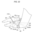
- Figs. 16 to 22 are views for describing usage examples of the hemostatic device 10 according to the embodiment.
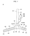
- the hemostatic device 10 can be used for hemostasis of a first puncture site p1 formed on a hand H located on a distal side (fingertip side) with respect to a forearm portion Ar of a patient when a sheath tube 610 of an introducer 600 indwelled in the first puncture site p1 is removed.
- a specific position of the puncture site, which is a hemostasis target of the hemostatic device 10, is not particularly limited, but in the present embodiment, the first puncture site p1 and a second puncture site p2 are exemplified.
- the first puncture site p1 is a puncture site formed in a distal radial artery (hereinafter, also referred to as a "blood vessel V1") located on a distal side of a snuff box Sb of a palmar artery running on a dorsal side of a right hand H1 located on the distal side with respect to the forearm portion Ar of the patient.
- a blood vessel V1 located on a distal radial artery located on a distal side of a snuff box Sb of a palmar artery running on a dorsal side of a right hand H1 located on the distal side with respect to the forearm portion Ar of the patient.
- the first puncture site p1 is located at a predetermined position, which is a position between a metacarpal bone B1 of an index finger and a metacarpal bone B2 of a thumb and avoiding the metacarpal bone B1 of the index finger and the metacarpal bone B2 of the thumb.
- the snuff box Sb is a cavity in the hand located in the vicinity of the radius when the patient spreads the thumb of the hand H.
- the second puncture site p2 is a puncture site formed in an artery V2 located in the snuff box Sb of the palmar artery running on the dorsal side of the right hand H1.
- the second puncture site p2 is located on the forearm portion Ar side (proximal side) of the patient with respect to the first puncture site p1, and is located between an extensor pollicis longus muscle tendon T1 and an extensor pollicis brevis muscle tendon T2 located at the dorsal side of the right hand H1 of the patient.
- the second puncture site p2 is located at a predetermined position avoiding the position of the metacarpal bone B1 of the index finger and the position of the metacarpal bone B2 of the thumb.
- the hemostatic device 10 can also be applied to hemostasis of a puncture site on the left hand of the patient formed at a position corresponding to the first puncture site p1 exemplified in the right hand H1 of the patient or a puncture site on the left hand of the patient formed at a position corresponding to the second puncture site p2 exemplified in the right hand H1 of the patient.
- hemostatic device 10 will be described in detail.
- the hemostatic device 10 includes a cover member 100 configured to cover the first puncture site p1 and a pressing member 200 connected to the cover member 100 and configured to compress the first puncture site p1.
- the pressing member 200 can include an inflatable member 210 that is inflatable by injection of a fluid.
- the pressing member 200 includes the inflatable member 210 will be described.
- the inflatable member 210 includes an inner cavity 210a into which a fluid can be injected.
- the inflatable member 210 is configured to inflate as a result of the injection of the fluid into the inner cavity 210a and deflate as a result of the discharge of the fluid injected into the inner cavity 210a.
- the fluid used to inflate the inflatable member 210 is, for example, a gas such as air.
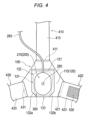
- Figs. 6 and 7 illustrate cross-sectional views of the inflatable member 210 in an inflated state.
- a tube 283 (see Figs. 1 and 2 ) to be described below is coupled to the inner cavity 210a of the inflatable member 210.
- the inflatable member 210 can include, for example, a film-like member (sheet material) connected to a sheet material 120 constituting a main body portion 110 of the cover member 100.
- the inflatable member 210 may be disposed to form the inner cavity 210a with respect to a lower surface region 132 of a holding portion 130 formed by the sheet material 120.
- An outer peripheral edge of the film-like member constitutes an edge portion 211 of the inflatable member 210.
- the edge portion 211 of the inflatable member 210 can be connected to the sheet material 120 by, for example, fusing, bonding, or the like.
- the film-like member constituting the inflatable member 210 can be made of, for example, a resin material having a predetermined thickness.
- a material for the film-like member constituting the inflatable member 210 is not particularly limited, and examples thereof include polyvinyl chloride, polyethylene, polypropylene, polybutadiene, polyolefin such as ethylenevinyl acetate copolymer (EVA), polyester such as polyethylene terephthalate (PET) or polybutylene terephthalate (PBT), various thermoplastic elastomers such as polyvinylidene chloride, silicone, polyurethane, polyamide elastomer, polyurethane elastomer or polyester elastomer, nylon, nylon elastomer, or any combination thereof (e.g., blended resin, polymer alloy, laminate, or the like).
- EVA ethylenevinyl acetate copolymer
- PET polyethylene terephthalate
- PBT polybutylene terephthalate
- various thermoplastic elastomers such as polyvinylidene chloride, silicone, polyurethane, polyamide elastomer,
- the specific configuration of the inflatable member 210 included in the hemostatic device 10 is not particularly limited.
- the inflatable member 210 may be formed by joining an edge portion of one sheet-like member to another sheet-like member in a state where the inner cavity 210a is formed between the two sheet-like members.
- the inflatable member 210 connects the surface of the one sheet-like member to the sheet material 120 constituting the main body portion 110 of the cover member 100.
- the inflatable member 210 can also include, for example, one bag-shaped member shaped to include the inner cavity 210a inside. In such a case, the inflatable member 210 connects a part of the surface of the bag-shaped member to the sheet material 120 constituting the main body portion 110 of the cover member 100.
- the inflatable member 210 is disposed on an inner surface 110a side of the main body portion 110 of the cover member 100.
- the inner surface 110a of the main body portion 110 includes a surface disposed on the body surface side of the hand H in the lower surface region 132 of the holding portion 130 when the hemostatic device 10 is attached on the hand H of the patient (see Figs. 21 and 22 ).
- An outer surface 110b of the main body portion 110 includes a surface on a side disposed facing the outside in an upper surface region 131 of the holding portion 130.
- Fig. 8 illustrates a positional relationship between the inflatable member 210 in a deflated state and a support member 300 in plan view.
- the inflatable member 210 is indicated by the two-dot chain line.
- the inflatable member 210 has a longitudinal width wa passing through a center c1 of the inflatable member 210 and a lateral width wb orthogonal to the longitudinal width wa and passing through the center c1 of the inflatable member 210 in a state where the inflatable member 210 is deflated.
- the longitudinal width wa and the lateral width wb described above are dimensions that do not include the edge portion 211 located on the outer periphery of the inflatable member 210, and mean the longitudinal width wa and the lateral width wb in the outer shape of the inflatable member 210 illustrated in plan view illustrated in Fig. 8 .
- the center c1 of the inflatable member 210 is located at the center of the outer shape illustrated in plan view of Fig. 8 .
- the center c1 is located at a position where a center position of an axis (long axis) along the longitudinal width wa and a center position of an axis (short axis) along the lateral width wb intersect.
- the center position of the axis (long axis) along the longitudinal width wa is a line segment passing through a point where distances from both ends of the axis along the longitudinal width wa are equal on the axis along the longitudinal width wa.
- the center position of the axis (short axis) along the lateral width wb is a line segment passing through a point where distances from both ends of the axis along the lateral width wb are equal on the axis along the lateral width wb.
- the lateral width wb of the inflatable member 210 is shorter than the longitudinal width wa.
- the inflatable member 210 has a substantially oval shape that is rotationally symmetric relative to the center c1 in plan view illustrated in Fig. 8 .
- the planar shape of the inflatable member 210 is not particularly limited.
- the inflatable member 210 may be configured to have a planar shape such as a circular shape, an elliptical shape, or a rectangular shape. Even when the inflatable member 210 is configured to have a planar shape such as a circular shape, an elliptical shape, or a rectangular shape, the center of the inflatable member 210 can be defined by the center position of the outer shape in plan view.
- the inflatable member 210 includes a marker portion 260 for aligning the inflatable member 210 with the first puncture site p1.
- the marker portion 260 can include a transparent central portion surrounding the center c1 and a colored circular frame portion surrounding the central portion.
- the marker portion 260 is disposed on the outer surface of the inflatable member 210. Note that the marker portion 260 may be disposed on the inner surface facing the inner cavity 210a of the inflatable member 210.
- the marker portion 260 can also include, for example, a circular marker configured entirely to be colored, a marker including a transparent central portion and a rectangular frame portion, a rectangular marker configured entirely to be colored, or the like.
- the cover member 100 includes the main body portion 110 where the inflatable member 210 is located, a first band body portion 410 configured to be disposed between fingers of the patient and extending from the main body portion 110 in a first direction, a second band body portion 420 extending from the main body portion 110 in a second direction different from the first direction, and a third band body portion 430 facing the second band body portion 420 across the inflatable member 210 and extending from the main body portion 110 in a third direction different from the first direction and the second direction.
- a region of the cover member 100 where the inflatable member 210 is disposed (a region overlapping the inflatable member 210 in plan view illustrated in Fig. 5 ) constitutes the main body portion 110.
- the main body portion 110 includes the holding portion 130 that holds the support member 300.
- the holding portion 130 can include a part of the sheet material 120 constituting the cover member 100.
- a part of the sheet material 120 is folded back from the proximal side (the side disposed on the forearm portion Ar) to the distal side (the side disposed on the fingertip) such that a space portion g is formed at a position overlapping the main body portion 110 in plan view illustrated in Fig. 5 .
- An end portion 121 located on the distal side of the folded-back portion of the sheet material 120 is connected to the main body portion 110.
- the space portion g is closed between the end portion 121 and the proximal portion 122 in the longitudinal width wa direction (see the cross section illustrated in Fig. 6 ).
- a second band body portion 420 side and a third band body portion 430 side communicate with the outside in the lateral width wb direction (see the cross section illustrated in Fig. 7 ).
- constricted portions 132a and 132b in which the width of the lower surface region 132 gradually decreases toward the curved region 133 are formed in the vicinity of the curved region 133 of the holding portion 130 (in the vicinity of the proximal portion 122 of the main body portion 110).
- the first band body portion 410 includes one end portion 411 connected to the main body portion 110 of the cover member 100, an other end portion 412 located on the opposite side of the one end portion 411, and a main body portion 413 extending between the one end portion 411 and the other end portion 412.
- the second band body portion 420 includes one end portion 421 connected to the main body portion 110 of the cover member 100, an other end portion 422 located on the opposite side of the one end portion 421, and a main body portion 423 extending between the one end portion 421 and the other end portion 422.
- the second direction in which the second band body portion 420 extends is not particularly limited as long as it is a direction different from the first direction in which the first band body portion 410 extends.
- the third band body portion 430 includes one end portion 431 connected to the main body portion 110 of the cover member 100, an other end portion 432 located on the opposite side of the one end portion 431, and a main body portion 433 extending between the one end portion 431 and the other end portion 432.
- the third direction in which the third band body portion 430 extends is not particularly limited as long as it is a direction different from the first direction in which the first band body portion 410 extends and the second direction in which the second band body portion 420 extends.
- the second band body portion 420 and the third band body portion 430 can be disposed so as to be wrapped along the outer periphery of the right hand H1 when the hemostatic device 10 is attached to the right hand H1 of the patient.
- the second band body portion 420 and the third band body portion 430 are located at positions facing each other across the inflatable member 210. Therefore, when the second band body portion 420 and the third band body portion 430 are wrapped around the right hand H1, a tensile force in a direction in which the second band body portion 420 and the third band body portion 430 move away from each other is applied to the second band body portion 420 and the third band body portion 430, and a tensile force in the same direction is also applied to the main body portion 110.
- each of the band body portions 410, 420, and 430 is not particularly limited, and each of the band body portions 410, 420, and 430 can be made of, for example, a vinyl chloride resin, a polyurethane resin, a polyester resin, or the like.
- the shape, length, thickness, and the like of each of the band body portions 410, 420, and 430 are not particularly limited.
- securing sites including a first securing site 510, a second securing site 520, a third securing site 530, and a fourth securing site 540 capable of securing the cover member 100 to the right hand H1 are disposed on each of the band body portions 410, 420, and 430.
- the first securing site 510 is disposed on the outer surface of the main body portion 423 of the second band body portion 420.
- the second securing site 520 is disposed on an outer surface of the main body portion 433 of the third band body portion 430.
- the third securing site 530 is disposed on an inner surface of the main body portion 423 of the second band body portion 420.
- the fourth securing site 540 is disposed on an inner surface of the main body portion 413 of the first band body portion 410.
- the first securing site 510 and the second securing site 520 are configured on a male side of a hook-and-loop fastener.
- the third securing site 530 and the fourth securing site 540 are configured on a female side of the hook-and-loop fastener.
- the hook-and-loop fastener in the present specification is a fastener that is attachable to and detachable from the surface, and is, for example, Magic Tape (registered trademark) or Velcro (registered trademark).
- the second band body portion 420 and the third band body portion 430 are configured to be attachable and detachable via the third securing site 530 located on the inner surface of the main body portion 423 of the second band body portion 420 and the second securing site 520 located on the outer surface of the main body portion 433 of the third band body portion 430.
- the first band body portion 410 and the second band body portion 420 are configured to be attachable and detachable via the fourth securing site 540 located on the inner surface of the main body portion 413 of the first band body portion 410 and the first securing site 510 located on the outer surface of the main body portion 423 of the second band body portion 420.
- securing sites 510, 520, 530, and 540 are not limited as long as the cover member 100 can be secured to the right hand H1 by connecting the band body portions 410, 420, and 430 to each other in a state where the hemostatic device 10 is disposed on the right hand H1.
- installation of some of the securing sites can be omitted, and positions where the securing sites are disposed on the band body portions 410, 420, and 430, and the like can be arbitrarily changed.
- each of the securing sites 510, 520, and 530 when each of the securing sites 510, 520, and 530 is configured as a hook-and-loop fastener, the male side and the female side of the hook-and-loop fastener may be configured to be interchanged.
- each of the securing sites 510, 520, 530, and 540 may include, for example, a coupling mechanism or the like including a frame portion formed with a snap, a button, a clip, a protrusion, and an engaged portion in which a hole engageable with the frame portion is formed.
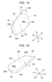
- Figs. 8 to 15 illustrate the support member 300.
- arrows X1-X2 indicate the longitudinal direction of the support member 300 (the same direction as the longitudinal width wa direction of the inflatable member 210)
- arrows Y1-Y2 indicate the width direction of the support member 300 (the same direction as the lateral width wb direction of the inflatable member 210)
- arrows Z1-Z2 indicate the thickness direction of the support member 300.
- the support member 300 includes an upper end portion 301 located on the first band body portion 410 side and forming an end portion of the support member 300, a lower end portion 302 forming an end portion opposite to the upper end portion 301, and a pair of side surface portions 303 and 304 connecting the upper end portion 301 and the lower end portion 302.
- the upper end portion 301 can be disposed on the fingertip side (distal side) of the finger in a state where the hemostatic device 10 is attached to the right hand H1.
- the lower end portion 302 can be disposed on the forearm portion Ar side (proximal side) in a state where the hemostatic device 10 is attached to the right hand H1.
- the support member 300 is configured such that width w1 of the support member 300 decreases from upper end portion 301 toward the lower end portion 302.
- a thickness t2 (see Fig. 9 ) of the end surface located on the upper end portion 301 side is formed to be thicker than a thickness t3 (see Fig. 10 ) of the end surface located on the lower end portion 302 side. Therefore, as illustrated in Fig. 11 , the support member 300 is configured such that thickness t1 of the side surface portions 303 and 304 connecting the upper end portion 301 and the lower end portion 302 decreases from the upper end portion 301 toward the lower end portion 302. That is, in the cross-sectional view illustrated in Fig. 6 and the cross-sectional view illustrated in Fig. 20 , the support member 300 is inclined such that a space between an outer surface 300b and an inner surface 300a decreases from the upper end portion 301 toward the lower end portion 302.
- the inner surface 300a of the support member 300 is a surface disposed on the lower surface region 132 side of the holding portion 130.
- the outer surface 300b of the support member 300 is a surface disposed on the upper surface region 131 side of the holding portion 130 (see Fig. 6 ).
- the lower end portion 302 of the support member 300 has a flat portion 302a having a linear shape in plan view illustrated in Fig. 8 .
- the flat portion 302a extends substantially linearly between corner portions 306a and 306b located on the lower end portion 302 side.
- the upper end portion 301 of the support member 300 has a flat portion 301a having a linear shape in plan view illustrated in Fig. 8 .
- the flat portion 301a extends substantially linearly between corner portions 306c and 306d located on the upper end portion 301 side.
- the outer surface 300b of the support member 300 is curved toward the second band body portion 420 and third band body portion 430 sides. That is, on the outer surface 300b of the support member 300, a top portion protruding most is located in the vicinity of the center of the support member 300 in a width direction.
- the top portion of the outer surface 300b of the support member 300 is located along the longitudinal direction of the support member 300. That is, the top portion of the outer surface 300b of the support member 300 is located along the longitudinal direction passing through an intermediate portion 305.
- the curvature radius of the outer surface 300b of the support member 300 is substantially constant at each portion in the longitudinal direction of the support member 300.
- the corner portions 306a, 306b, 306c, and 306d located at the four corners of the support member 300 are formed in a rounded curved shape.
- the support member 300 has the intermediate portion 305 located between the upper end portion 301 and the lower end portion 302 in plan view illustrated in Fig. 8 .
- the intermediate portion 305 is located in the middle in the longitudinal direction connecting the upper end portion 301 and the lower end portion 302.
- the support member 300 has a bilaterally symmetrical shape relative to a center line C of the first band body portion 410 (axis along the extending direction of the first band body portion 410) in the main body portion 110.
- the support member 300 has a bilaterally symmetrical shape relative to a line segment that is orthogonal to an axis along a width w1' of the upper end portion 301 and passes through a point where distances from both ends of the width w1' of the upper end portion 301 are equal in plan view of Fig. 8 .
- the support member 300 can be disposed on the main body portion 110 so as to be bilaterally symmetrical relative to the center line C of the first band body portion 410 (axis along the extending direction of the first band body portion 410).
- the side surface portions 303 and 304 are formed to be bilaterally symmetrical relative to the center line C of the first band body portion 410 in the main body portion 110.
- the side surface portions 303 and 304 extend bilaterally symmetrically such that the width w1 of the support member 300 decreases at a substantially constant rate from the upper end portion 301 side toward the lower end portion 302 side.
- the injection portion 281 includes a connector having an incorporated check valve (not illustrated).
- a syringe (not illustrated) can be connected to the injection portion 281.
- a buffer member 282 having an inflatable space is disposed between the injection portion 281 and the inflatable member 210.
- the buffer member 282 includes a flexible bag-shaped member having a space formed inside. Note that the buffer member 282 may be provided with an arrow-shaped marker indicating a direction in which the syringe is inserted into the injection portion 281.
- the injection portion 281 is connected to one end side of the buffer member 282. A lumen of the injection portion 281 communicates with the space in the buffer member 282. However, when the check valve incorporated in the injection portion 281 is closed, communication between the lumen of the injection portion 281 and the space of the buffer member 282 is cut off.
- the inflatable member 210 When the air is injected into the inner cavity 210a of the inflatable member 210, the inflatable member 210 is inflated. When the inflatable member 210 is inflated, the buffer member 282 communicating with the inner cavity 210a of the inflatable member 210 via the tube 283 expands. The operator can easily understand that the inflatable member 210 is inflated without leakage of air by visually confirming expansion of the buffer member 282.
- the operator inserts the distal tubular portion of the syringe to the injection portion 281 and pulls the plunger of the syringe.
- the operator can discharge the air in the inner cavity 210a of the inflatable member 210 to the syringe.
- the injection portion 281, the buffer member 282, and the tube 283 may be prepared and provided in a state of being coupled to the inflatable member 210, or may be prepared and provided in a state of being separated from the inflatable member 210.
- the injection portion 281 is not particularly limited as to a specific configuration or the like as long as the supply of the fluid to the inner cavity 210a of the inflatable member 210 and the discharge of the fluid from the inner cavity 210a of the inflatable member 210 can be operated.
- Fig. 17 illustrates a state after performing various procedures performed using the sheath tube 610 of the introducer 600 inserted into the first puncture site p1.
- the operator disposes the inflatable member 210 and the support member 300 so as to overlap the first puncture site p1.
- the operator can appropriately position the inflatable member 210 and the support member 300 at the first puncture site p1 by disposing the marker portion 260 at the first puncture site p1 while visually confirming the position of the marker portion 260 disposed on the inflatable member 210.
- the operator disposes the support member 300 so that the support member 300 overlaps the metacarpal bone B1 of the index finger and the metacarpal bone B2 of the thumb.
- an interval between the metacarpal bone B1 of the index finger and the metacarpal bone B2 of the thumb gradually decreases from the fingertip side toward the forearm portion Ar side.
- the width w1 of the support member 300 becomes shorter from the upper end portion 301 disposed on the fingertip side toward the lower end portion 302 disposed on the forearm portion Ar side (see Fig. 8 ).
- the operator can dispose the support member 300 along the metacarpal bone B1 of the index finger and the metacarpal bone B2 of the thumb by disposing the support member 300 to overlap the metacarpal bone B1 of the index finger and the metacarpal bone B2 of the thumb from the dorsal side of the right hand H1 of the patient.
- the operator can prevent a gap from being formed between the inflatable member 210 disposed on the inner surface 300a side of the support member 300 and the right hand H1 by disposing the support member 300 along the metacarpal bone B1 of the index finger and the metacarpal bone B2 of the thumb.
- the operator wraps the second band body portion 420 and the third band body portion 430 along the outer periphery of the right hand H1 of the patient.
- the operator can connect the second band body portion 420 and the third band body portion 430 via the securing sites 520 and 530 by bringing the third securing site 530 (see Fig. 2 ) disposed on the inner surface of the second band body portion 420 into contact with the second securing site 520 (see Fig. 1 ) disposed on the outer surface of the third band body portion 430.
- the operator can firmly wrap the band body portions 420 and 430 along the outer periphery of the right hand H1 by connecting the band body portions 420 and 430 to each other in a state where the support member 300 overlaps the metacarpal bone B1 of the index finger and the metacarpal bone B2 of the thumb.
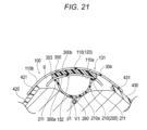
- the outer surface 300b of the support member 300 is curved toward the second band body portion 420 side (side surface portion 303 side) and the third band body portion 430 side (side surface portion 304 side) (see Figs. 5 , 9 , and 10 ). Therefore, as illustrated in Fig. 18 , by wrapping the second band body portion 420 and the third band body portion 430 along the right hand H1 of the patient, the support member 300 can be pressed to the right hand H1 from the outer surface 300b side along the outer periphery of the right hand H1 as illustrated in Fig. 21 . Therefore, the hemostatic device 10 can increase the securing force of the support member 300 and the inflatable member 210 to the right hand H1 of the patient.
- the operator passes the first band body portion 410 through the inter-finger portion fb located between the thumb and the index finger of the right hand H1 of the patient, and disposes a part of the first band body portion 410 on the palm side of the right hand H1 of the patient.
- the operator can connect the first band body portion 410 and the second band body portion 420 via the securing sites 510 and 540 by bringing the fourth securing site 540 (see Fig. 2 ) disposed on the inner surface of the first band body portion 410 into contact with the first securing site 510 (see Fig. 1 ) disposed on the outer surface of the second band body portion 420.
- the support member 300 includes the upper end portion 301 and the side surface portions 303 and 304.
- the first band body portion 410 extends from the upper end portion 301 side
- the second band body portion 420 extends from the side surface portion 303 side
- the third band body portion 430 extends from the side surface portion 304 side (see Fig. 5 ). Therefore, the hemostatic device 10 can secure the support member 300 to the right hand H1 of the patient in a state in which a uniform force is applied to the position corresponding to each portion 301, 303, and 304 of the support member 300 by connecting the band body portions 410, 420, and 430 to each other.
- the width w1' of the upper end portion 301 of the support member 300 is longer than the lateral width wb of the inflatable member 210, and the width w1'' of the lower end portion 302 of the support member 300 is shorter than the lateral width wb of the inflatable member 210 (see Fig. 8 ).
- the inflatable member may be displaced to the lower end portion side (forearm portion Ar side) of the support member that is located on the side opposite to the side where the first band body portion is tightened.
- the width w1'' of the lower end portion 302 of the support member 300 is shorter than the lateral width wb of the inflatable member 210 as described above, and it is possible to suppress that the inflatable member 210 is displaced to the lower end portion 302 side of the support member 300.
- the support member 300 is curved in a protruding shape such that the inner surface 300a of the support member 300 is away from the inflatable member 210 (see Figs. 14 and 21 ). Therefore, the support member 300 can press both end portions in a lateral width direction of the inflatable member 210 at positions of both end portions in the width direction of the inner surface 300a of the support member 300. Therefore, the hemostatic device 10 can effectively prevent the inflatable member 210 from being displaced toward the lower end portion 302 side of the support member 300 when the inflatable member 210 is inflated.
- the support member 300 is bilaterally symmetrical relative to the center line C of the first band body portion 410 in the main body portion 110 (see Figs. 5 and 8 ). Therefore, the hemostatic device 10 can uniformly apply a force along a bilaterally symmetrical direction to the support member 300 by wrapping the band body portions 420 and 430 bilaterally symmetrically extending based on the first band body portion 410 around the right hand H1 of the patient. Accordingly, the hemostatic device 10 can prevent displacement of the support member 300 in a state where the support member 300 is disposed on the right hand H1 of the patient.
- the inner surface 300a of the support member 300 is curved in a protruding shape in a direction away from the inflatable member 210 (see Figs. 7 and 21 ).
- An inclined portion is present in each portion (for example, the vicinity of the snuff box Sb) of the right hand H1 of the patient.
- the shape of the inclined portion of the right hand H1 depends on individual differences of the patient. For example, when the inner surface of the support member is formed in a flat shape, it is difficult to dispose the support member along the inclined portion of the right hand H1.
- the inner surface 300a of the support member 300 of the hemostatic device 10 has a shape curved in a protruding shape in a direction away from the inflatable member 210 as described above.
- the hemostatic device 10 can dispose the support member 300 to overlap the first puncture site p1 without depending on the dominant hand of the patient or the way of placing by the operator. Therefore, when the hemostatic device 10 performs hemostatic compression at the first puncture site p1 using the inflatable member 210, the support member 300 can be suitably disposed at a desired position in the vicinity of the first puncture site p1.
- the hemostatic device 10 can be disposed such that each of the band body portions 420 and 430 extending from each of the side surface portions 303 and 304 of the support member 300 approaches or adheres to the body surface of the right hand H1 of the patient (see Fig. 21 ). Therefore, the hemostatic device 10 can increase the securing force of the support member 300 and the inflatable member 210 to the right hand H1 of the patient. Therefore, in a state where the hemostatic device 10 is attached to the right hand H1 of the patient, the support member 300 and the inflatable member 210 are less likely to be displaced even when an impact or the like is applied from the outside.
- the operator inflates the inflatable member 210 by injecting air into the inflatable member 210 in a state where the syringe is connected to the injection portion 281.
- the inflatable member 210 when the inflatable member 210 is inflated, the inflatable member 210 applies a compressive force to the first puncture site p1.
- the support member 300 presses the inflatable member 210 to the right hand H1 of the patient. Accordingly, the hemostatic device 10 can prevent the inflatable member 210 from lifting from the right hand H1 of the patient.
- the operator can more strongly tighten, for example, the first band body portion disposed at the inter-finger portion fb so as to increase the securing force of the support member with respect to the right hand H1 of the patient.
- the operator can strongly tightening the first band body portion, the operator can firmly secure the support member to the right hand H1 of the patient even when the support member is disposed in an unstable state on the right hand H1 of the patient.
- the first band body portion is strongly tightened, the patient may feel pain.
- the hemostatic device may be disposed such that the inner surface of the support member is inclined with respect to the body surface of the right hand H1 of the patient. Specifically, the upper end portion of the support member on which the first band body portion is disposed is more excessively lifted to a position away from the body surface of the right hand of the patient than the lower end portion located on the opposite side of the upper end portion. Accordingly, in the hemostatic device, the support member is disposed in an inclined manner such that the distance between the inner surface of the support member and the body surface of the right hand H1 of the patient gradually decreases from the upper end portion toward the lower end portion of the support member.
- the thickness t1 of the side surface portions 303 and 304 of the support member 300 is configured to decrease from the upper end portion 301 toward the lower end portion 302.
- the first band body portion 410 configured to be disposed at the inter-finger portion fb located between the fingers of the patient extends from the upper end portion 301 side of the support member 300 and is configured to press the upper end portion 301 side of the support member 300 to the right hand H1 of the patient.
- the inflatable member 210 when the inflatable member 210 starts inflating in a state where the support member 300 and the inflatable member 210 are secured to the right hand H1 of the patient, the inflatable member 210 applies a force to vicinity of the upper end portion 301 of the support member 300.
- the upper end portion 301 side of the support member 300 is lifted by the force applied by the inflatable member 210. Accordingly, as illustrated in Fig. 20 , when the inflatable member 210 is in an inflated state, the support member 300 is disposed such that the inner surface 300a of the support member 300 is substantially parallel to the body surface of the right hand H1 of the patient. Therefore, when the inflatable member 210 is inflated, the hemostatic device 10 can apply a compressive force to the first puncture site p1 in a vertical direction.
- the inner surface 300a of the support member 300 is curved in a protruding shape in a direction away from the inflatable member 210 (see Figs. 7 and 21 ). Therefore, as illustrated in Fig. 21 , the hemostatic device 10 is disposed such that the support member 300 is along the body surface of the right hand H1 of the patient in a state where the inflatable member 210 is inflated. When the inflatable member 210 is inflated, the hemostatic device 10 presses the inflatable member 210 along the body surface of the right hand H1 of the patient using the inner surface 300a of the support member 300.
- the inflatable member 210 applies a compressive force in a direction toward the first puncture site p1 from the center side in the width direction of the inner surface 300a of the support member 300 and the side surface portions 303 and 304 located at both end portions in the width direction of the inner surface 300a of the support member 300. Therefore, the hemostatic device 10 can effectively increase the compressive force applied to the first puncture site p1 using the inflatable member 210 as compared with the case where the inner surface 300a of the support member 300 is formed in a flat surface shape.
- the hemostatic device 10 configured as described above, when the inflatable member 210 is inflated, the support member 300 is lifted from the body surface of the right hand H1 of the patient on the lower end portion 302 side where the center c1 of the inflatable member 210 is disposed with respect to the upper end portion 301 side where the gravity center G1 is located as a result of the inflation of the inflatable member 210. Therefore, the hemostatic device 10 can prevent the lower end portion 302 of the support member 300 disposed on the wrist or forearm portion Ar side of the patient from biting into the body surface while the inflatable member 210 inflated in a state where the hemostatic device 10 is attached to the right hand H1 of the patient applies a compressive force to the first puncture site p1.
- the support member 300 is bilaterally symmetrical relative to the center line C of the first band body portion 410.
- the inner surface 300a of the support member 300 is curved in a protruding shape in a direction away from the pressing member 200.
- the hemostatic device 10 since the support member 300 is bilaterally symmetrical relative to the center line C of the first band body portion 410 in the main body portion 110, the hemostatic device 10 can uniformly apply a force along a bilaterally symmetrical direction to the support member 300 by wrapping the band body portions 420 and 430 bilaterally symmetrically extending based on the first band body portion 410 around the right hand H1 of the patient. Accordingly, the hemostatic device 10 can prevent displacement of the support member 300 in a state where the support member 300 is disposed on the right hand H1 of the patient.
- the hemostatic device 10 since the inner surface 300a of the support member 300 is curved in a protruding shape in a direction away from the pressing member 200, when the inner surface 300a of the support member 300 is disposed to overlap the inclined portion of the right hand H1 of the patient, the inner surface 300a of the support member 300 can be disposed along the right hand H1 of the patient. Accordingly, the hemostatic device 10 can dispose the support member 300 to overlap the first puncture site p1 without depending on the dominant hand of the patient or the way of placing by the operator. Therefore, when the hemostatic device 10 performs hemostatic compression at the first puncture site p1 using the inflatable member 210, the support member 300 can be suitably disposed at a desired position in the vicinity of the first puncture site p1.
- the inflatable member 210 applies a compressive force in a direction toward the first puncture site p1 from the center side in the width direction of the inner surface 300a of the support member 300 and the side surface portions 303 and 304 located at both end portions in the width direction of the inner surface 300a of the support member 300. Therefore, the hemostatic device 10 can effectively increase the compressive force applied to the first puncture site p1 using the inflatable member 210 as compared with the case where the inner surface 300a of the support member 300 is formed in a flat surface shape.
- the curvature radius of the inner surface 300a of the upper end portion 301 of the support member 300 is smaller than the curvature radius of the inner surface 300a of the lower end portion 302 of the support member 300.
- the curvature radius of the inner surface 300a of the upper end portion 301 disposed at the fingertip side position of the extensor pollicis longus muscle tendon T1 and the extensor pollicis brevis muscle tendon T2 is small, and the curvature radius of the inner surface 300a of the lower end portion 302 disposed at the forearm portion Ar side position of the extensor pollicis longus muscle tendon T1 and the extensor pollicis brevis muscle tendon T2 is large so as to correspond to a change in distance between the extensor pollicis longus muscle tendon T1 and the extensor pollicis brevis muscle tendon T2.
- the hemostatic device 10 when the support member 300 is disposed on the right hand H1 of the patient for hemostasis at the second puncture site p2, the hemostatic device 10 is disposed such that the support member 300 is along the extensor pollicis longus muscle tendon T1 and the extensor pollicis brevis muscle tendon T2. As a result, the hemostatic device 10 can firmly secure the support member 300 to the vicinity of the second puncture site p2 located in the vicinity of the snuff box Sb at the time of hemostasis at the second puncture site p2.
- the pressing member 200 is the inflatable member 210 that can be inflated by injection of a fluid.
- the inflatable member 210 has a longitudinal width wa passing through a center c1 of the inflatable member 210 and a lateral width wb orthogonal to the longitudinal width wa and passing through the center c1 of the inflatable member 210 in a state where the inflatable member 210 is deflated.
- the lateral width wb is shorter than the longitudinal width wa.
- the width w1' of the upper end portion 301 of the support member 300 is longer than the lateral width wb of the inflatable member 210, and the width w1'' of the lower end portion 302 is shorter than the lateral width wb of the inflatable member 210.
- the width w1' of the upper end portion 301 of the support member 300 is longer than the lateral width wb of the inflatable member 210, and the width w1" of the lower end portion 302 of the support member 300 is shorter than the lateral width wb of the inflatable member 210, and therefore, when the inflatable member 210 disposed at the first puncture site p1 is inflated, the inflatable member 210 is supported by both end portions in the width direction of the lower end portion 302 of the support member 300. Therefore, the hemostatic device 10 can suppress the inflatable member 210 from being displaced toward the lower end portion 302 side of the support member 300 when the inflatable member 210 is inflated.
- the hemostatic device according to the modification is different from the hemostatic device 10 according to the above-described embodiment in the structure of a pressing member 200A (inflatable member 210A).
- the inflatable member 210 includes one sheet material connected to the main body portion 110 of the cover member 100 (see Figs. 6 and 7 ).
- the inflatable member 210A is configured by connecting an edge portion 221 of a first sheet material 220 and an edge portion 231 of a second sheet material 230.
- the thickness of the first sheet material 220 is configured to be larger than the thickness of the second sheet material 230.
- Figs. 23 and 24 are partial cross-sectional views of the hemostatic device according to the modification.
- Fig. 23 illustrates a state before the inflatable member 210A is inflated
- Fig. 24 illustrates a state in which the inflatable member 210A is inflated.
- Figs. 23 and 24 are cross-sectional views corresponding to Fig. 7 of the above-described embodiment.
- the pressing member 200A includes the inflatable member 210A that is inflatable by injection of a fluid.
- the inflatable member 210A is formed by connecting the edge portion 221 located at the outer peripheral edge of the first sheet material 220 and the edge portion 231 located at the outer peripheral edge of the second sheet material 230.
- the inner cavity 210a is formed between the first sheet material 220 and the second sheet material 230.
- the edge portion 221 of the first sheet material 220 and the edge portion 231 of the second sheet material 230 can be connected by, for example, bonding or fusing.
- the first sheet material 220 is connected to the cover member 100 at a position overlapping the support member 300.
- the inflatable member 210A is secured to the cover member 100 by connecting the first sheet material 220 to a part of the cover member 100 (the surface of the holding portion 130).
- the first sheet material 220 is secured to the cover member 100 by connecting a part of the edge portion 221 of the first sheet material 220 to the holding portion 130. Note that, as illustrated in Fig. 23 , the first sheet material 220 and the holding portion 130 are connected at two opposing positions.
- the edge portion 231 of the second sheet material 230 is located at the edge portion (end portion in the lateral width wb direction located on each side surface portions 303 and 304 side of the support member 300) of the support member 300.
- the edge portion 231 of the second sheet material 230 is located in this manner, the edge portion of the inflatable member 210A is supported by the edge portion of the support member 300.
- the edge portion 221 of the first sheet material 220 and the edge portion 231 of the second sheet material 230 are located at the edge portion (end portion in the lateral width wb direction located on each side surface portions 303 and 304 side of the support member 300) of the support member 300.
- the inflatable member 210A is configured such that a portion including the second sheet material 230 has a larger inflation deformation amount than a portion including the first sheet material 220 in a state where the inflatable member 210A is inflated.
- the thickness of the second sheet material 230 is thinner than the thickness of the first sheet material 220. Therefore, when a fluid such as air is injected into the inner cavity 210a, the portion including the second sheet material 230 inflates and deforms more than the portion including the first sheet material 220 in the inflatable member 210A.
- a position where the first sheet material 220 and the second sheet material 230 are connected (position where the edge portions 221 and 231 are connected) in an up-down direction in the drawing, which is the inflation direction, is set at a position deviated on the support member 300 side with respect to the center position of the entire inflatable member 210A.
- the edge portion 231 in the present modification, the edge portions 221 and 231 of the sheet materials 220 and 230
- the inflatable member 210A uniformly inflates in the lateral width wb direction of the support member 300. Accordingly, when the inflatable member 210A applies the compressive force to each of the puncture sites p1 and p2, the inflation amount in the lateral width wb direction of the support member 300 becomes uniform. Therefore, the shape of the inflatable member 210A at the time of maximum inflation and the compressive force applied to the puncture sites p1 and p2 are stabilized.
- the inflation deformation amount of the first sheet material 220 is smaller than that of the second sheet material 230. Therefore, the inflatable member 210A can be prevented from being deformed such that when the inflatable member 210A is inflated, a portion of the inflatable member 210A including the first sheet material 220 excessively protrudes toward the inner surface 300a side of the support member 300. Therefore, in the inflatable member 210A, the area of contact between the inner surface 300a of the support member 300 and the first sheet material 220 increases in a state where the inflatable member 210A is inflated.
- the support member 300 can firmly press the inflatable member 210 by increasing the contact area between the inner surface 300a of the support member 300 and the inflatable member 210A. Therefore, in the hemostatic device according to the modification, the compressive force applied to each of the puncture sites p1 and p2 by the inflatable member 210A is further improved.
- hemostatic device according to the present invention has been described above in conjunction with the embodiment and the modification, the present invention is not limited only to the content described in the specification and can be appropriately changed on the basis of the description of the claims.
- each portion of the hemostatic device are not particularly limited as long as hemostatic compression can be performed on the puncture site using the pressing member disposed on the puncture site, and can be appropriately changed.
- the specific shapes (planar shape and cross-sectional shape) of the inflatable member and the support member are not limited to the shapes illustrated in the embodiment.
- the pressing member may include, for example, a resin material such as plastic configured to be able to apply a compressive force to the puncture site, a member made of gel or the like, an elastic material such as a sponge-like substance, an assembly of fibers such as cotton, metal, a member having a predetermined three-dimensional shape (spherical, ellipsoid, triangular pyramid, or the like), or a combination thereof as appropriate.
- a resin material such as plastic configured to be able to apply a compressive force to the puncture site
- a member made of gel or the like an elastic material such as a sponge-like substance, an assembly of fibers such as cotton, metal, a member having a predetermined three-dimensional shape (spherical, ellipsoid, triangular pyramid, or the like), or a combination thereof as appropriate.
Landscapes
- Health & Medical Sciences (AREA)
- Life Sciences & Earth Sciences (AREA)
- Surgery (AREA)
- Heart & Thoracic Surgery (AREA)
- Molecular Biology (AREA)
- Vascular Medicine (AREA)
- Engineering & Computer Science (AREA)
- Biomedical Technology (AREA)
- Reproductive Health (AREA)
- Medical Informatics (AREA)
- Nuclear Medicine, Radiotherapy & Molecular Imaging (AREA)
- Animal Behavior & Ethology (AREA)
- General Health & Medical Sciences (AREA)
- Public Health (AREA)
- Veterinary Medicine (AREA)
- Biophysics (AREA)
- Hematology (AREA)
- Surgical Instruments (AREA)
Applications Claiming Priority (2)
| Application Number | Priority Date | Filing Date | Title |
|---|---|---|---|
| JP2022044656 | 2022-03-18 | ||
| PCT/JP2023/008988 WO2023176667A1 (ja) | 2022-03-18 | 2023-03-09 | 止血器具 |
Publications (2)
| Publication Number | Publication Date |
|---|---|
| EP4494575A1 true EP4494575A1 (de) | 2025-01-22 |
| EP4494575A4 EP4494575A4 (de) | 2026-02-25 |
Family
ID=88023261
Family Applications (1)
| Application Number | Title | Priority Date | Filing Date |
|---|---|---|---|
| EP23770623.9A Pending EP4494575A4 (de) | 2022-03-18 | 2023-03-09 | Hämostaseinstrument |
Country Status (5)
| Country | Link |
|---|---|
| US (1) | US20250000516A1 (de) |
| EP (1) | EP4494575A4 (de) |
| JP (1) | JPWO2023176667A1 (de) |
| CN (1) | CN118765179A (de) |
| WO (1) | WO2023176667A1 (de) |
Family Cites Families (5)
| Publication number | Priority date | Publication date | Assignee | Title |
|---|---|---|---|---|
| EP3703806A4 (de) | 2017-11-03 | 2021-05-26 | Merit Medical Systems, Inc. | Hämostasevorrichtungen und verfahren zur verwendung |
| JP7219013B2 (ja) | 2018-04-06 | 2023-02-07 | 株式会社シマノ | 人力駆動車用コンポーネント |
| JP2022029463A (ja) * | 2018-11-29 | 2022-02-18 | テルモ株式会社 | 止血器具 |
| JP7808037B2 (ja) * | 2020-08-21 | 2026-01-28 | テルモ株式会社 | 止血器具 |
| JP7853283B2 (ja) * | 2021-03-30 | 2026-04-28 | テルモ株式会社 | 止血器具 |
-
2023
- 2023-03-09 CN CN202380023862.3A patent/CN118765179A/zh active Pending
- 2023-03-09 EP EP23770623.9A patent/EP4494575A4/de active Pending
- 2023-03-09 WO PCT/JP2023/008988 patent/WO2023176667A1/ja not_active Ceased
- 2023-03-09 JP JP2024507824A patent/JPWO2023176667A1/ja active Pending
-
2024
- 2024-09-12 US US18/883,306 patent/US20250000516A1/en active Pending
Also Published As
| Publication number | Publication date |
|---|---|
| CN118765179A (zh) | 2024-10-11 |
| WO2023176667A1 (ja) | 2023-09-21 |
| EP4494575A4 (de) | 2026-02-25 |
| JPWO2023176667A1 (de) | 2023-09-21 |
| US20250000516A1 (en) | 2025-01-02 |
Similar Documents
| Publication | Publication Date | Title |
|---|---|---|
| EP3821827B1 (de) | Hämostasegerät | |
| US12096944B2 (en) | Hemostatic device | |
| US20230200825A1 (en) | Hemostatic device | |
| US20240000462A1 (en) | Hemostatic device | |
| US20240415524A1 (en) | Hemostatic device | |
| EP4494575A1 (de) | Hämostaseinstrument | |
| US20240074767A1 (en) | Hemostatic device | |
| EP3818951B1 (de) | Hämostatisches instrument | |
| JP7691278B2 (ja) | 止血器具 | |
| JP7523377B2 (ja) | 止血器具 | |
| US20250000517A1 (en) | Hemostatic device | |
| AU2024330355A1 (en) | Hemostasis instrument | |
| US20250000518A1 (en) | Hemostatic device | |
| US20240366232A1 (en) | Hemostatic device | |
| US20230201555A1 (en) | Hemostatic device | |
| US20240407790A1 (en) | Hemostatic device | |
| WO2023176665A1 (ja) | 止血器具 | |
| JP2025056815A (ja) | 止血器具 | |
| AU2024334013A1 (en) | Hemostatic instrument | |
| AU2024352012A1 (en) | Hemostatic device and hemostatic device set |
Legal Events
| Date | Code | Title | Description |
|---|---|---|---|
| STAA | Information on the status of an ep patent application or granted ep patent |
Free format text: STATUS: THE INTERNATIONAL PUBLICATION HAS BEEN MADE |
|
| PUAI | Public reference made under article 153(3) epc to a published international application that has entered the european phase |
Free format text: ORIGINAL CODE: 0009012 |
|
| STAA | Information on the status of an ep patent application or granted ep patent |
Free format text: STATUS: REQUEST FOR EXAMINATION WAS MADE |
|
| 17P | Request for examination filed |
Effective date: 20240911 |
|
| AK | Designated contracting states |
Kind code of ref document: A1 Designated state(s): AL AT BE BG CH CY CZ DE DK EE ES FI FR GB GR HR HU IE IS IT LI LT LU LV MC ME MK MT NL NO PL PT RO RS SE SI SK SM TR |
|
| DAV | Request for validation of the european patent (deleted) | ||
| DAX | Request for extension of the european patent (deleted) | ||
| A4 | Supplementary search report drawn up and despatched |
Effective date: 20260128 |
|
| RIC1 | Information provided on ipc code assigned before grant |
Ipc: A61B 17/135 20060101AFI20260122BHEP Ipc: A61B 17/132 20060101ALI20260122BHEP |