EP4494589A1 - Fixations d'électrode pour cathéters à panier - Google Patents
Fixations d'électrode pour cathéters à panier Download PDFInfo
- Publication number
- EP4494589A1 EP4494589A1 EP24189332.0A EP24189332A EP4494589A1 EP 4494589 A1 EP4494589 A1 EP 4494589A1 EP 24189332 A EP24189332 A EP 24189332A EP 4494589 A1 EP4494589 A1 EP 4494589A1
- Authority
- EP
- European Patent Office
- Prior art keywords
- electrode
- aperture
- spine
- pin
- tab
- Prior art date
- Legal status (The legal status is an assumption and is not a legal conclusion. Google has not performed a legal analysis and makes no representation as to the accuracy of the status listed.)
- Pending
Links
Images






Classifications
-
- A—HUMAN NECESSITIES
- A61—MEDICAL OR VETERINARY SCIENCE; HYGIENE
- A61B—DIAGNOSIS; SURGERY; IDENTIFICATION
- A61B18/00—Surgical instruments, devices or methods for transferring non-mechanical forms of energy to or from the body
- A61B18/04—Surgical instruments, devices or methods for transferring non-mechanical forms of energy to or from the body by heating
- A61B18/12—Surgical instruments, devices or methods for transferring non-mechanical forms of energy to or from the body by heating by passing a current through the tissue to be heated, e.g. high-frequency current
- A61B18/14—Probes or electrodes therefor
-
- A—HUMAN NECESSITIES
- A61—MEDICAL OR VETERINARY SCIENCE; HYGIENE
- A61B—DIAGNOSIS; SURGERY; IDENTIFICATION
- A61B18/00—Surgical instruments, devices or methods for transferring non-mechanical forms of energy to or from the body
-
- A—HUMAN NECESSITIES
- A61—MEDICAL OR VETERINARY SCIENCE; HYGIENE
- A61B—DIAGNOSIS; SURGERY; IDENTIFICATION
- A61B18/00—Surgical instruments, devices or methods for transferring non-mechanical forms of energy to or from the body
- A61B18/04—Surgical instruments, devices or methods for transferring non-mechanical forms of energy to or from the body by heating
- A61B18/12—Surgical instruments, devices or methods for transferring non-mechanical forms of energy to or from the body by heating by passing a current through the tissue to be heated, e.g. high-frequency current
- A61B18/14—Probes or electrodes therefor
- A61B18/1492—Probes or electrodes therefor having a flexible, catheter-like structure, e.g. for heart ablation
-
- A—HUMAN NECESSITIES
- A61—MEDICAL OR VETERINARY SCIENCE; HYGIENE
- A61B—DIAGNOSIS; SURGERY; IDENTIFICATION
- A61B18/00—Surgical instruments, devices or methods for transferring non-mechanical forms of energy to or from the body
- A61B2018/00053—Mechanical features of the instrument of device
-
- A—HUMAN NECESSITIES
- A61—MEDICAL OR VETERINARY SCIENCE; HYGIENE
- A61B—DIAGNOSIS; SURGERY; IDENTIFICATION
- A61B18/00—Surgical instruments, devices or methods for transferring non-mechanical forms of energy to or from the body
- A61B2018/00053—Mechanical features of the instrument of device
- A61B2018/0016—Energy applicators arranged in a two- or three dimensional array
-
- A—HUMAN NECESSITIES
- A61—MEDICAL OR VETERINARY SCIENCE; HYGIENE
- A61B—DIAGNOSIS; SURGERY; IDENTIFICATION
- A61B18/00—Surgical instruments, devices or methods for transferring non-mechanical forms of energy to or from the body
- A61B2018/00053—Mechanical features of the instrument of device
- A61B2018/00184—Moving parts
-
- A—HUMAN NECESSITIES
- A61—MEDICAL OR VETERINARY SCIENCE; HYGIENE
- A61B—DIAGNOSIS; SURGERY; IDENTIFICATION
- A61B18/00—Surgical instruments, devices or methods for transferring non-mechanical forms of energy to or from the body
- A61B2018/00053—Mechanical features of the instrument of device
- A61B2018/00214—Expandable means emitting energy, e.g. by elements carried thereon
- A61B2018/00267—Expandable means emitting energy, e.g. by elements carried thereon having a basket shaped structure
-
- A—HUMAN NECESSITIES
- A61—MEDICAL OR VETERINARY SCIENCE; HYGIENE
- A61B—DIAGNOSIS; SURGERY; IDENTIFICATION
- A61B18/00—Surgical instruments, devices or methods for transferring non-mechanical forms of energy to or from the body
- A61B2018/00315—Surgical instruments, devices or methods for transferring non-mechanical forms of energy to or from the body for treatment of particular body parts
- A61B2018/00345—Vascular system
- A61B2018/00351—Heart
-
- A—HUMAN NECESSITIES
- A61—MEDICAL OR VETERINARY SCIENCE; HYGIENE
- A61B—DIAGNOSIS; SURGERY; IDENTIFICATION
- A61B18/00—Surgical instruments, devices or methods for transferring non-mechanical forms of energy to or from the body
- A61B2018/00571—Surgical instruments, devices or methods for transferring non-mechanical forms of energy to or from the body for achieving a particular surgical effect
- A61B2018/00577—Ablation
-
- A—HUMAN NECESSITIES
- A61—MEDICAL OR VETERINARY SCIENCE; HYGIENE
- A61B—DIAGNOSIS; SURGERY; IDENTIFICATION
- A61B18/00—Surgical instruments, devices or methods for transferring non-mechanical forms of energy to or from the body
- A61B2018/00571—Surgical instruments, devices or methods for transferring non-mechanical forms of energy to or from the body for achieving a particular surgical effect
- A61B2018/00613—Irreversible electroporation
-
- A—HUMAN NECESSITIES
- A61—MEDICAL OR VETERINARY SCIENCE; HYGIENE
- A61B—DIAGNOSIS; SURGERY; IDENTIFICATION
- A61B18/00—Surgical instruments, devices or methods for transferring non-mechanical forms of energy to or from the body
- A61B18/04—Surgical instruments, devices or methods for transferring non-mechanical forms of energy to or from the body by heating
- A61B18/12—Surgical instruments, devices or methods for transferring non-mechanical forms of energy to or from the body by heating by passing a current through the tissue to be heated, e.g. high-frequency current
- A61B18/14—Probes or electrodes therefor
- A61B2018/1405—Electrodes having a specific shape
- A61B2018/1407—Loop
- A61B2018/141—Snare
-
- A—HUMAN NECESSITIES
- A61—MEDICAL OR VETERINARY SCIENCE; HYGIENE
- A61B—DIAGNOSIS; SURGERY; IDENTIFICATION
- A61B18/00—Surgical instruments, devices or methods for transferring non-mechanical forms of energy to or from the body
- A61B18/04—Surgical instruments, devices or methods for transferring non-mechanical forms of energy to or from the body by heating
- A61B18/12—Surgical instruments, devices or methods for transferring non-mechanical forms of energy to or from the body by heating by passing a current through the tissue to be heated, e.g. high-frequency current
- A61B18/14—Probes or electrodes therefor
- A61B2018/1467—Probes or electrodes therefor using more than two electrodes on a single probe
-
- A—HUMAN NECESSITIES
- A61—MEDICAL OR VETERINARY SCIENCE; HYGIENE
- A61B—DIAGNOSIS; SURGERY; IDENTIFICATION
- A61B18/00—Surgical instruments, devices or methods for transferring non-mechanical forms of energy to or from the body
- A61B18/04—Surgical instruments, devices or methods for transferring non-mechanical forms of energy to or from the body by heating
- A61B18/12—Surgical instruments, devices or methods for transferring non-mechanical forms of energy to or from the body by heating by passing a current through the tissue to be heated, e.g. high-frequency current
- A61B18/14—Probes or electrodes therefor
- A61B2018/1475—Electrodes retractable in or deployable from a housing
Definitions
- the present invention relates generally to medical devices, and in particular medical probes with electrodes, and further relates to, but not exclusively, medical probes suitable for use to induce irreversible electroporation (IRE) of cardiac tissues.
- IRE irreversible electroporation
- Cardiac arrhythmias such as atrial fibrillation (AF) occur when regions of cardiac tissue abnormally conduct electric signals to adjacent tissue. This disrupts the normal cardiac cycle and causes asynchronous rhythm. Certain procedures exist for treating arrhythmia, including surgically disrupting the origin of the signals causing the arrhythmia and disrupting the conducting pathway for such signals. By selectively ablating cardiac tissue by application of energy via a catheter, it is sometimes possible to cease or modify the propagation of unwanted electrical signals from one portion of the heart to another.
- AF atrial fibrillation
- RF ablation can have certain risks related to thermal heating which can lead to tissue charring, burning, steam pop, phrenic nerve palsy, pulmonary vein stenosis, and esophageal fistula.
- Cryoablation is an alternative approach to RF ablation that generally reduces thermal risks associated with RF ablation. Maneuvering cryoablation devices and selectively applying cryoablation, however, is generally more challenging compared to RF ablation; therefore, cryoablation is not viable in certain anatomical geometries which may be reached by electrical ablation devices.
- IRE irreversible electroporation
- Regions of cardiac tissue can be mapped by a catheter to identify the abnormal electrical signals.
- the same or different medical probe can be used to perform ablation.
- Some example probes include a number of spines with electrodes positioned thereon.
- the electrodes are generally attached to the spines and secured in place by soldering, welding, or using an adhesive. Due to the small size of the spines and the electrodes, however, soldering, welding, or adhering the electrodes to the spines can be a difficult task, increasing the manufacturing time and cost and the chances that the electrode fails due to an improper bond, misalignment, or strain on the spine. What is needed, therefore, are systems and methods of attaching an electrode to a spine of a basket assembly without the need for soldering, welding, or using adhesive.
- a spine assembly can include an elongated member extending along a longitudinal axis member comprising a first aperture along a length of the member.
- the assembly can include a first electrode slidable along the length of the member.
- the first electrode comprising a first electrode aperture.
- the assembly can include a first pin disposed within the first aperture and the first electrode aperture when the first aperture and the first electrode aperture are aligned along the length of the member.
- the first pin can include a non-conductive material.
- the first electrode aperture can have a non-conductive internal surface.
- a pin head of the first pin can have a beveled profile.
- the first pin can include a rivet having a bottom that is compressible to form a second head opposite a first head.
- the first head and the second head of the rivet can be positioned at opposing sides of the first electrode.
- the assembly can include a second electrode slidable along the length of the member.
- the second electrode can include a second electrode aperture.
- the assembly can include a second pin.
- the member can include a second aperture along the length of the member. The second pin can be disposed within the second aperture and the second electrode aperture when the second aperture and the second electrode aperture are aligned along the length of the member.
- the assembly can include a second pin.
- the member can include a second aperture.
- the first electrode can include a second electrode aperture, and the second pin can be disposed within the second aperture and the second electrode aperture when the second aperture and the second electrode aperture are aligned along the length of the member.
- the assembly can include a first tab and a second tab.
- the first tab can include the first electrode aperture, and the second tab can include the second electrode aperture.
- the first tab and the second tab can be positioned at opposite ends of the first electrode in a direction along the length of the member.
- the second electrode aperture can have a non-conductive internal surface.
- the disclosed technology can include an expandable basket assembly.
- the assembly can include at least one spine extending along a longitudinal axis and configured to bow radially outward from the longitudinal axis.
- the spine can include a first spine aperture and a second spine aperture disposed along a length of the spine.
- the assembly can include a first electrode slidable along the length of the spine.
- the first electrode can include a first electrode aperture and a second electrode aperture.
- the assembly can include a first pin disposed within the first spine aperture and the first electrode aperture when the first spine aperture and the first electrode aperture are aligned along the length of the spine.
- the assembly can include a second pin disposed within the second spine aperture and the second electrode aperture when the second spine aperture and the second electrode aperture are aligned along the length of the spine.
- the first pin and the second pin can include a non-conductive material.
- the first electrode aperture and the second electrode aperture can have non-conductive internal surfaces.
- a first pin head of the first pin can have a beveled profile, and a second pin head of the second pin can have a beveled profile.
- the first pin and the second pin can include rivets that are compressible to form a beveled end.
- the assembly can include a first tab and a second tab.
- the first tab can include the first electrode aperture
- the second tab can include the second electrode aperture.
- the first tab and the second tab can be positioned at opposite ends of the first electrode in a direction along the length of the spine.
- the first tab and the second tab can be connected to and extending from the first electrode.
- the first electrode aperture and the second electrode aperture can have non-conductive internal surfaces.
- the disclosed technology can include an expandable basket assembly.
- the assembly can include at least one spine extending along a longitudinal axis.
- the spine can include a first spine aperture along a length of the spine.
- the assembly can include a first electrode slidable along the length of the spine.
- the first electrode can include a first electrode aperture.
- the assembly can include a first rivet disposed within the first spine aperture and the first electrode aperture when the first spine aperture and the first electrode aperture are aligned along the length of the spine.
- the first rivet can include a non-conductive material.
- the first electrode aperture can have a non-conductive internal surface.
- a rivet head of the first rivet can have a beveled profile.
- the rivet can include a multi-piece component having a rivet top connectable to a rivet bottom. The rivet top and the rivet bottom can be positioned at opposing sides of the first electrode when connected.
- the assembly can include a second electrode slidable along the length of the spine, the second electrode comprising a second electrode aperture.
- the assembly can include a second rivet.
- the spine can include a second spine aperture along the length of the spine. The second rivet can be disposed within the second spine aperture and the second electrode aperture when the second spine aperture and the second electrode aperture are aligned along the length of the spine.
- the assembly can include a second rivet.
- the spine can include a second spine aperture.
- the first electrode can include a second electrode aperture.
- the second rivet can be disposed within the second spine aperture and the second electrode aperture when the second spine aperture and the second electrode aperture are aligned along the length of the spine.
- the assembly can include a first tab and a second tab.
- the first tab can include the first electrode aperture
- the second tab can include the second electrode aperture.
- the first tab and the second tab can be positioned at opposite ends of the first electrode in a direction along the length of the spine.
- the second electrode aperture can have a non-conductive internal surface.
- the disclosed technology can include an expandable basket assembly.
- the assembly can include at least one spine extending along a longitudinal axis.
- the spine can include a first spine attachment along a length of the spine.
- the first spine attachment can be an aperture, or a position along a length of a slot along the length of the spine.
- the assembly can include a first electrode slidable along the length of the spine.
- the first electrode can include an extension insertable into the first spine attachment and compressible to form a compressed base.
- the disclosed technology can further include a method of attaching an electrode to an elongated member.
- the method can include placing a first electrode at an end of the elongated member.
- the method can include sliding the first electrode along a length of the member until a first electrode aperture of the first electrode aligns with a first aperture of the member.
- the method can include inserting a first pin into the first electrode aperture and the first aperture to affix the first electrode to the member.
- Placing the first electrode at the end of the member can include placing the end of the member into a slot of the first electrode. The member being slidable through the slot.
- the method can include inserting a second pin into a second electrode aperture and a second aperture to affix the first electrode to the member.
- the first electrode aperture can be disposed within a first tab
- the second electrode aperture can be disposed within a second tab.
- the first tab and the second tab can extend from a main body of the first electrode.
- the first pin can include a rivet having a first rivet head.
- the method can further include deforming a bottom of the first pin to secure the first pin within the first electrode aperture and the first aperture.
- the first pin can include a rivet having a first rivet head.
- the method can further include connecting a rivet bottom to the first pin to secure the first pin within the first electrode aperture and the first aperture.
- Sliding the first electrode along a length of the member until a first electrode aperture of the first electrode aligns with a first aperture of the member can include sliding the first electrode past a second aperture.
- the method can further include placing a second electrode at the end of the member.
- the method can further include sliding the second electrode along the length of the member until a second electrode aperture of the second electrode aligns with the second aperture.
- the method can further include inserting a second pin into the first electrode aperture and the second aperture to affix the second electrode to the member.
- the disclosed technology can further include a method of attaching an electrode to a spine of a basket catheter.
- the method can include sliding a first electrode along a length of the spine until a first electrode aperture of the first electrode aligns with a first spine aperture of the spine, and a second electrode aperture of the first electrode aligns with a second spine aperture of the spine.
- the method can include inserting a first pin into the first electrode aperture and the first spine aperture to affix the first electrode to the spine.
- the method can include inserting a second pin into the second electrode aperture and the second spine aperture.
- the method can include placing the end of the spine into a spine slot of the first electrode, the spine being slidable through the spine slot.
- the first electrode aperture can be disposed within a first tab
- the second electrode aperture can be disposed within a second tab.
- the first tab and the second tab can extend from a main body of the first electrode.
- the first pin and the second pin are rivets can have a rivet head.
- the method can further include deforming bottoms of the first pin and the second pin to secure the pins within the first electrode aperture and the first spine aperture.
- the first pin can include a rivet having a first rivet head.
- the second pin can include a rivet having a second rivet head.
- the method further includes connecting a first rivet bottom to the first pin to secure the first pin within the first electrode aperture and the first spine aperture.
- the method further includes connecting a second rivet bottom to the second pin to secure the second pin within the second electrode aperture and the second spine aperture.
- Sliding the first electrode along a length of the spine until a first electrode aperture of the first electrode aligns with a first spine aperture of the spine can include sliding the first electrode past a third spine aperture and a fourth spine aperture.
- the method can further include sliding a second electrode along the length of the spine until a third electrode aperture of the second electrode aligns with a third spine aperture of the spine, and a fourth electrode aperture of the second electrode aligns with a fourth spine aperture of the spine.
- the method can further include inserting a third pin into the third electrode aperture and the third spine aperture to affix the second electrode to the spine.
- the method can further include inserting a fourth pin into the fourth electrode aperture and the fourth spine aperture.
- the disclosed technology can further include a method of securing an electrode to an elongated member.
- the method can include sliding a first tab along a length of a spine until a first electrode aperture of the first tab aligns with a first spine aperture of the spine.
- the method can include inserting a first pin into the first electrode aperture and the first spine aperture to affix the first tab to the spine.
- the method can include sliding a first electrode along the length of the spine until the first electrode contacts the first tab.
- the method can include sliding a second tab along the length of the spine until a second electrode aperture of the second tab aligns with a second spine aperture of the spine.
- the method can include inserting a second pin into the second electrode aperture and the second spine aperture to affix the second tab to the spine.
- the disclosed technology can further include a method of attaching an electrode to a spine of a basket catheter.
- the method can include sliding a first electrode along a length of the spine until a first electrode aperture of the first electrode aligns with a first spine aperture of the spine.
- the method can include inserting a first rivet into the first electrode aperture and the first spine aperture.
- the method can include riveting the first rivet to affix the first electrode to the spine.
- the method can include placing the end of the spine into a spine slot of the first electrode.
- the spine can be slidable through the spine slot.
- Riveting the first rivet can include connecting a rivet bottom to the first rivet to affix the first electrode to the spine.
- Sliding the first electrode along a length of the spine until a first electrode aperture of the first electrode aligns with a first spine aperture of the spine can include sliding the first electrode past a second spine aperture.
- the method can further include sliding a second electrode along a length of the spine until a second electrode aperture of the second electrode aligns with the second spine aperture.
- the method can further include inserting a second rivet into the second electrode aperture and the second spine aperture.
- the method can further include riveting the second rivet to affix the second electrode to the spine.
- the disclosed technology can further include a method of securing an electrode to an elongated member.
- the method can include sliding a first electrode along a length of a spine until it reaches a spine attachment on the spine.
- the method can include compressing an extension of the first electrode to form a compressed base at an end of the extension, thereby securing the first electrode to the spine at a location of the spine attachment.
- the terms “about” or “approximately” for any numerical values or ranges indicate a suitable dimensional tolerance that allows the part or collection of components to function for its intended purpose as described herein. More specifically, “about” or “approximately” may refer to the range of values ⁇ 20% of the recited value, e.g. “about 90%” may refer to the range of values from 71% to 110%.
- the terms “patient,” “host,” “user,” and “subject” refer to any human or animal subject and are not intended to limit the systems or methods to human use, although use of the subject invention in a human patient represents a preferred embodiment.
- proximal indicates a location closer to the operator or physician whereas “distal” indicates a location further away to the operator or physician.
- vasculature of a "patient,” “host,” “user,” and “subject” can be vasculature of a human or any animal.
- an animal can be a variety of any applicable type, including, but not limited thereto, mammal, veterinarian animal, livestock animal or pet type animal, etc.
- the animal can be a laboratory animal specifically selected to have certain characteristics similar to a human (e.g., rat, dog, pig, monkey, or the like).
- the subject can be any applicable human patient, for example.
- doctor can include a doctor, surgeon, technician, scientist, or any other individual or delivery instrumentation associated with delivery of a multi-electrode catheter for the treatment of drug refractory atrial fibrillation to a subject.
- IRE irreversible electroporation
- PEF pulsed electric field
- PFA pulsed field ablation
- Ablating or ablation as it relates to the devices and corresponding systems of this disclosure is used throughout this disclosure in reference to non-thermal ablation of cardiac tissue for certain conditions including, but not limited to, arrhythmias, atrial flutter ablation, pulmonary vein isolation, supraventricular tachycardia ablation, and ventricular tachycardia ablation.
- the term “ablate” or “ablation” also includes known methods, devices, and systems to achieve various forms of bodily tissue ablation as understood by a person skilled in
- bipolar and unipolar when used to refer to ablation schemes describe ablation schemes which differ with respect to electrical current path and electric field distribution.
- Bipolar refers to ablation scheme utilizing a current path between two electrodes that are both positioned at a treatment site; current density and electric flux density is typically approximately equal at each of the two electrodes.
- Unipolar refers to ablation scheme utilizing a current path between two electrodes where one electrode having a high current density and high electric flux density is positioned at a treatment site, and a second electrode having comparatively lower current density and lower electric flux density is positioned remotely from the treatment site.
- biphasic pulse and “monophasic pulse” refer to respective electrical signals.
- Biphasic pulse refers to an electrical signal having a positive-voltage phase pulse (referred to herein as “positive phase”) and a negative-voltage phase pulse (referred to herein as “negative phase”).
- Monophasic pulse refers to an electrical signal having only a positive or only a negative phase.
- a system providing the biphasic pulse is configured to prevent application of a direct current voltage (DC) to a patient.
- DC direct current voltage
- the average voltage of the biphasic pulse can be zero volts with respect to ground or other common reference voltage.
- the system can include a capacitor or other protective component.
- each phase of the biphasic and/or monophasic pulse preferably has a square shape having an essentially constant voltage amplitude during a majority of the phase duration.
- Phases of the biphasic pulse are separated in time by an interphase delay.
- the interphase delay duration is preferably less than or approximately equal to the duration of a phase of the biphasic pulse.
- the interphase delay duration is more preferably about 25% of the duration of the phase of the biphasic pulse.
- tubular and tube are to be construed broadly and are not limited to a structure that is a right cylinder or strictly circumferential in cross-section or of a uniform cross-section throughout its length.
- the tubular structures are generally illustrated as a substantially right cylindrical structure.
- the tubular structures may have a tapered or curved outer surface without departing from the scope of the present disclosure.
- the present disclosure is related to systems, method or uses and devices for IRE ablation of cardiac tissue to treat cardiac arrhythmias.
- Ablative energies are typically provided to cardiac tissue by a tip portion of a catheter which can deliver ablative energy alongside the tissue to be ablated.
- Some example catheters include three-dimensional structures at the tip portion and are configured to administer ablative energy from various electrodes positioned on the three-dimensional structures. Ablative procedures incorporating such example catheters can be visualized using fluoroscopy.
- a thermal technique such as radio frequency (RF) energy and cryoablation
- RF radio frequency
- cryoablation to correct a malfunctioning heart
- cardiac electropotentials need to be measured at various locations of the myocardium.
- temperature measurements during ablation provide data enabling the efficacy of the ablation.
- the electropotentials and the temperatures are measured before, during, and after the actual ablation.
- RF approaches can have risks that can lead to tissue charring, burning, steam pop, phrenic nerve palsy, pulmonary vein stenosis, and esophageal fistula.
- Cryoablation is an alternative approach to RF ablation that can reduce some thermal risks associated with RF ablation.
- maneuvering cryoablation devices and selectively applying cryoablation is generally more challenging compared to RF ablation; therefore, cryoablation is not viable in certain anatomical geometries which may be reached by electrical ablation devices.
- the present disclosure can include electrodes configured for RF ablation, cryoablation, and/or irreversible electroporation (IRE).
- IRE can be referred to throughout this disclosure interchangeably as pulsed electric field (PEF) ablation and pulsed field ablation (PFA).
- PEF pulsed electric field
- PFA pulsed field ablation
- IRE as discussed in this disclosure is a non-thermal cell death technology that can be used for ablation of atrial arrhythmias.
- biphasic voltage pulses are applied to disrupt cellular structures of myocardium.
- the biphasic pulses are non-sinusoidal and can be tuned to target cells based on electrophysiology of the cells.
- IRE In contrast, to ablate using RF, a sinusoidal voltage waveform is applied to produce heat at the treatment area, indiscriminately heating all cells in the treatment area. IRE therefore has the capability to spare adjacent heat sensitive structures or tissues which would be of benefit in the reduction of possible complications known with ablation or isolation modalities. Additionally, or alternatively, monophasic pulses can be utilized.
- Electroporation can be induced by applying a pulsed electric field across biological cells to cause reversable (temporary) or irreversible (permanent) creation of pores in the cell membrane.
- the cells have a transmembrane electrostatic potential that is increased above a resting potential upon application of the pulsed electric field. While the transmembrane electrostatic potential remains below a threshold potential, the electroporation is reversable, meaning the pores can close when the applied pulse electric field is removed, and the cells can self-repair and survive. If the transmembrane electrostatic potential increases beyond the threshold potential, the electroporation is irreversible, and the cells become permanently permeable.
- the cells die due to a loss of homeostasis and typically die by apoptosis.
- cells of differing types have differing threshold potential. For instance, heart cells have a threshold potential of approximately 500 V/cm, whereas for bone it is 3000 V/cm. These differences in threshold potential allow IRE to selectively target tissue based on threshold potential.
- the solution of this disclosure includes systems and methods for applying electrical signals from catheter electrodes positioned in the vicinity of myocardial tissue to generate a generate ablative energy to ablate the myocardial tissue.
- the systems and methods can be effective to ablate targeted tissue by inducing irreversible electroporation.
- the systems and methods can be effective to induce reversible electroporation as part of a diagnostic procedure. Reversible electroporation occurs when the electricity applied with the electrodes is below the electric field threshold of the target tissue allowing cells to repair. Reversible electroporation does not kill the cells but allows a physician to see the effect of reversible electroporation on electrical activation signals in the vicinity of the target location.
- Example systems and methods for reversible electroporation is disclosed in U.S. Patent Publication 2021/0162210 , the entirety of which is incorporated herein by reference and attached in the Appendix hereto.
- the pulsed electric field, and its effectiveness to induce reversible and/or irreversible electroporation, can be affected by physical parameters of the system and biphasic pulse parameters of the electrical signal.
- Physical parameters can include electrode contact area, electrode spacing, electrode geometry, etc. Examples presented herein generally include physical parameters adapted to effectively induce reversible and/or irreversible electroporation.
- Biphasic pulse parameters of the electrical signal can include voltage amplitude, pulse duration, pulse interphase delay, inter-pulse delay, total application time, delivered energy, etc.
- parameters of the electrical signal can be adjusted to induce both reversible and irreversible electroporation given the same physical parameters. Examples of various systems and methods of ablation including IRE are presented in U.S.
- System 10 includes multiple catheters, which are percutaneously inserted by physician 24 through the patient's 23 vascular system into a chamber or vascular structure of a heart 12.
- a delivery sheath catheter is inserted into the left or right atrium near a desired location in heart 12.
- a plurality of catheters can be inserted into the delivery sheath catheter so as to arrive at the desired location.
- the plurality of catheters may include catheters dedicated for sensing Intracardiac Electrogram (IEGM) signals, catheters dedicated for ablating and/or catheters dedicated for both sensing and ablating.
- An example catheter 14 that is configured for sensing IEGM is illustrated herein.
- Physician 24 brings a distal tip of catheter 14 (i.e., a basket assembly 28 in this case) into contact with the heart wall for sensing a target site in heart 12.
- a catheter 14 with a distal basket assembly can be referred to as a basket catheter.
- physician 24 would similarly bring a distal end of an ablation catheter to a target site for ablating.
- Catheter 14 is an exemplary catheter that includes one and preferably multiple electrodes 26 optionally distributed over a plurality of spines 22 at basket assembly 28 and configured to sense the IEGM signals.
- Catheter 14 may additionally include a position sensor embedded in or near basket assembly 28 for tracking position and orientation of basket assembly 28.
- position sensor is a magnetic based position sensor including three magnetic coils for sensing three-dimensional (3D) position and orientation.
- Magnetic based position sensor may be operated together with a location pad 25 including a plurality of magnetic coils 32 configured to generate magnetic fields in a predefined working volume.
- Real time position of basket assembly 28 of catheter 14 may be tracked based on magnetic fields generated with location pad 25 and sensed by magnetic based position sensor. Details of the magnetic based position sensing technology are described in U.S. Patent Nos. 5,391,199 ; 5,443,489 ; 5,558,091 ; 6,172,499 ; 6,239,724 ; 6,332,089 ; 6,484,118 ; 6,618,612 ; 6,690,963 ; 6,788,967 ; 6,892,091 , each of which are incorporated herein by reference and attached in the Appendix hereto.
- System 10 includes one or more electrode patches 38 positioned for skin contact on patient 23 to establish location reference for location pad 25 as well as impedance-based tracking of electrodes 26.
- impedance-based tracking electrical current is directed toward electrodes 26 and sensed at electrode skin patches 38 so that the location of each electrode can be triangulated via the electrode patches 38. Details of the impedance-based location tracking technology are described in US Patent Nos. 7,536,218 ; 7,756,576 ; 7,848,787 ; 7,869,865 ; and 8,456,182 , each of which are incorporated herein by reference and attached in the Appendix hereto.
- a recorder 11 displays electrograms 21 captured with body surface ECG electrodes 18 and intracardiac electrograms (IEGM) captured with electrodes 26 of catheter 14.
- Recorder 11 may include pacing capability for pacing the heart rhythm and/or may be electrically connected to a standalone pacer.
- System 10 may include an ablation energy generator 50 that is adapted to conduct ablative energy to one or more of electrodes at a distal tip of a catheter configured for ablating.
- Energy produced by ablation energy generator 50 may include, but is not limited to, radiofrequency (RF) energy or pulsed-field ablation (PFA) energy, including monopolar or bipolar high-voltage DC pulses as may be used to effect irreversible electroporation (IRE), or combinations thereof.
- RF radiofrequency
- PFA pulsed-field ablation
- IRE irreversible electroporation
- Patient interface unit (PIU) 30 is an interface configured to establish electrical communication between catheters, electrophysiological equipment, power supply and a workstation 55 for controlling operation of system 10.
- Electrophysiological equipment of system 10 may include for example, multiple catheters, location pad 25, body surface ECG electrodes 18, electrode patches 38, ablation energy generator 50, and recorder 11.
- PIU 30 additionally includes processing capability for implementing real-time computations of location of the catheters and for performing ECG calculations.
- Workstation 55 includes memory, processor unit with memory or storage with appropriate operating software loaded therein, and user interface capability. Workstation 55 may provide multiple functions, optionally including (1) modeling the endocardial anatomy in three-dimensions (3D) and rendering the model or anatomical map 20 for display on a display device 27, (2) displaying on display device 27 activation sequences (or other data) compiled from recorded electrograms 21 in representative visual indicia or imagery superimposed on the rendered anatomical map 20, (3) displaying real-time location and orientation of multiple catheters within the heart chamber, and (5) displaying on display device 27 sites of interest such as places where ablation energy has been applied.
- One commercial product embodying elements of the system 10 is available as the CARTOTM 3 System, available from Biosense Webster, Inc., 31 Technology Drive, Suite 200, Irvine, CA 92618 USA.
- FIG. 2A is a schematic pictorial illustration showing a perspective view of a medical probe 39 with electrodes 26 in an expanded form, such as by being advanced out of a tubular shaft lumen 80 at a distal end of a tube 31, in accordance with an embodiment of the present invention.
- FIG. 2B shows a medical probe 39 with electrodes 26 in a collapsed form within tube 31.
- one or more spines 22 bow radially outwardly and in the collapsed form ( FIG. 2B ) the spines 22 are arranged generally along a longitudinal axis 86 of tubular shaft 84.
- the medical probe 39 includes a plurality of flexible spines 22 that are formed at the end of a tubular shaft 84 and can be connected at their ends.
- medical professional 34 can deploy medical probe 39 by extending tubular shaft 84 from tube 31 causing the medical probe 39 to exit the tube 31 and transition to the expanded form.
- Spines 22 may have elliptical (e.g., circular) or rectangular (that may appear to be flat) cross-sections, and include a flexible, resilient material (e.g., a shape-memory alloy such as nickel-titanium, also known as Nitinol) forming a strut as will be described in greater detail herein.
- a shape-memory alloy such as nickel-titanium, also known as Nitinol
- the basket assembly 28 shown in FIGs. 2A-2B having spines 22 formed from a single sheet of planar material and converging at a central intersection is offered merely for illustrative purposes and the disclosed technology can be applicable to other configurations of basket assemblies 28.
- the disclosed technology can be applicable to basket assemblies 28 formed from a single spine 22 or multiple spines 22 with each spine 22 being attached at both ends.
- the basket assembly 28 can include a central hub connecting the multiple spines 22 together at a distal end of the basket assembly 28.
- the basket assembly 28 can include a single spine 22 configured to form a spiral, multiple spines 22 configured to form a spiral, multiple spines 22 configured to form a tripod or multiple tripods, or any other shape of basket assembly 28.
- FIGs. 2A-2B illustrate a specific configuration of basket assembly 28, the disclosed technology should not be construed as so limited.
- the basket assembly 28 can be formed by laser cutting a cylindrical hollow stock material whereby the laser is mounted for rotation about the longitudinal axis (and translation thereto) of the cylindrical stock while cutting. It will be understood that catheter devices that include a basket assembly 28 (as shown herein) cam be referred to as basket catheters.
- the spines 22 can be formed from a single sheet of planar material to form a generally star shape.
- the spines 22 can be formed from the single sheet of planar material such that the spines 22 converge toward a central intersection.
- the intersection can be a solid piece of material or include one or more apertures.
- the spine 22 can be electrically isolated from the electrode 26 to prevent arcing from the electrode 26 to the spine 22.
- insulative jackets can be positioned between the spine(s) 22 and the electrode(s) 26, but one of skill in the art will appreciate that other insulative coverings are contemplated.
- an insulative coating can be applied to the spine 22, the electrodes 26, or both.
- the insulative jackets can be made from a biocompatible, electrically insulative material such as polyamide-polyether (Pebax) copolymers, polyethylene terephthalate (PET), urethanes, polyimide, parylene, silicone, etc.
- insulative material can include biocompatible polymers including, without limitation, polyetheretherketone (PEEK), polyglycolic acid (PGA), poly(lactic-co-glycolic acid) copolymer (PLGA), polycaprolactive (PCL), poly(3-hydroxybutyrate-co-3-hydroxyvalerate) (PHBV), poly-L-lactide, polydioxanone, polycarbonates, and polyanhydrides with the ratio of certain polymers being selected to control the degree of inflammatory response.
- PEEK polyetheretherketone
- PGA polyglycolic acid
- PLGA poly(lactic-co-glycolic acid) copolymer
- PCL polycaprolactive
- PHBV poly(3-hydroxybutyrate-co-3-hydroxyvalerate)
- poly-L-lactide polydioxanone
- polycarbonates polyanhydrides with the ratio of certain polymers being selected to control the degree of inflammatory response.
- Insulative jackets may also include one or more additives or fillers, such as, for example, polytetrafluoroethylene (PTFE), boron nitride, silicon nitride, silicon carbide, aluminum oxide, aluminum nitride, zinc oxide, and the like.
- PTFE polytetrafluoroethylene
- electrodes 26 can be configured to deliver ablation energy (RF and/or IRE) to tissue in heart 12.
- the electrodes can also be used to determine the location of medical probe 39 and/or to measure a physiological property such as local surface electrical potentials at respective locations on tissue in heart 12.
- the electrodes 26 can be biased such that a greater portion of the electrode 26 faces outwardly from the medical probe 39 such that the electrodes 26 deliver a greater amount of electrical energy outwardly away from the medical probe 39 (i.e., toward the heart 12 tissue) than inwardly toward the medical probe 39.
- Examples of materials ideally suited for forming electrodes 26 include gold, platinum, and palladium (and their respective alloys). These materials also have high thermal conductivity which allows the minimal heat generated on the tissue (i.e., by the ablation energy delivered to the tissue) to be conducted through the electrodes to the back side of the electrodes (i.e., the portions of the electrodes on the inner sides of the spines), and then to the blood pool in heart 12.
- FIGs. 3A-3F are schematic pictorial illustrations showing an electrode 326 and its engagement with a medical probe 39.
- FIGs. 3A-3C show the process of assembly and attachment of an electrode 326 onto a member of the medical probe 39, for example onto a spine 22 of the medical probe 39.
- the electrode 326 shown in FIGs. 3A-3F can be similar to the electrode 26 described above.
- the electrode 326 is not fully attached but is partially slid along a spine 22.
- the spine 22 can include an aperture 322 positioned along a length L1 of the spine 22 that corresponds to an intended position of the electrode 326.
- the aperture 322 can align with an electrode aperture 328 on the electrode 326 when the electrode 326 is seated into its assembled position.
- FIG. 3B shows the electrode 326 slid into its seated position such that the aperture 322 aligns with the electrode aperture 328.
- a pin 350 can be inserted into the aligned aperture 322/electrode aperture 328 so as to connect the electrode 326 at its final position on the spine 22 (see FIG. 3C ).
- FIG. 2A For illustration, certain implementations of basket catheters include more than one electrode along the length L1 of one spine. To seat the distalmost electrode, the electrode must be slid past a proximal electrode placement location. A system that includes attachment features (e.g., tabs and the like) formed directly onto the spine to engage with the electrodes makes it difficult to advance the distalmost electrode past the proximal electrode placement location.
- attachment features e.g., tabs and the like
- each spine 22 can have one electrode, two electrodes, and so forth, and each of the electrodes can be attached to the spine 22 according to any of the embodiments described in this disclosure.
- the electrode 326 can have a rectangular cross-section, as shown, or another cross-sectional geometry such as an elliptical (e.g., circular) cross-section.
- the electrode aperture 328 can have a non-conductive internal surface 330.
- the inside of the aperture that accepts the pin 350 can be coated with a biocompatible, electrically insulative material such as Pebax copolymers, PET, urethanes, polyimide, parylene, silicone, PEEK, PGA, PLGA, PCL, PHBV, poly-L-lactide, polydioxanone, polycarbonates, and/or the like.
- the electrode 326 can have a spine slot 332 disposed therethrough that can be sized and shaped to accept the spine 22. The electrode 326 can therefore slide down the length L1 of the spine 22 via engagement of the spine 22 within the spine slot 332.
- the internal surface of the spine slot 332 can have a coating to provide additional friction between the electrode 326 and the spine 22, such as silicone and the like.
- the perimeter of the spine aperture 322 can be coated in a non-conductive material, and the pin 350 and the electrode aperture 328 can remain conductive. A goal is to keep the electrode 326 and the spine 22 electrically isolated from each other, but the surfaces that touch (i.e., the pin 350, the electrode aperture, and spine aperture 322) can be interchanged such that there is an insulative connection between the surfaces.
- the pin 350 can be manufactured from a non-conductive material.
- the pin 350 can be made from a biocompatible, electrically insulative material such as Pebax copolymers, PET, urethanes, polyimide, parylene, silicone, PEEK, PGA, PLGA, PCL, PHBV, poly-L-lactide, polydioxanone, polycarbonates, and/or the like.
- the pin 350 can be manufactured from a metallic material or another potentially conductive material. In these examples, the pin 350 can be coated in said non-conductive material.
- the non-conductivity can, again, protect the pin 350 from becoming the point of electrical conduction, and as such the entire upper surface of the electrode 326 continues to be the ablation surface.
- the pin 350 can include features to assist in securing the pin 350 inside of the electrode aperture 328.
- the pin 350 can be a ball lock pin, a threaded pin, a spring pin, and the like.
- the pin 350 can be a rivet, as will be described herein with respect to FIGs. 5A-5G .
- a head of the pin 350 can have a beveled profile so as to provide an atraumatic profile (see FIG. 3D ).
- the head of the pin 350 can extend above the surface of the electrode 326 as shown in FIG. 3D .
- the head of the pin 350 may be recessed into the body of the electrode.
- the electrode aperture 328 can also include a countersunk portion to house, and lower, the head of the pin 350.
- FIGs. 4A-4F are schematic pictorial illustrations showing an electrode 426 and its engagement with a medical probe 39.
- FIGs. 4A-4C show the process of assembly and attachment of an electrode 426 onto a member of the medical probe 39, for example onto a spine 22 of the medical probe 39.
- the electrode 426 shown in FIGs. 4A-4F can be similar to electrode 26 and electrode 326 described above.
- the electrode 426 in FIGs. 4A-4F provides two points of attachment to a spine 22. Referring to FIG. 4A , the electrode 426 is not fully attached but is partially slid down a length L1 of a spine 22.
- the spine 22 can include a first spine aperture 422 positioned along the length L1 of the spine 22, and can include a second spine aperture 423 positioned along the length L1 of the spine 22.
- the electrode 426 can include a first electrode aperture 428 and a second electrode aperture 429.
- the distance L2 between the first spine aperture 422 and the second spine aperture 423 can be the same as the distance L3 between the first electrode aperture 428 and the second electrode aperture 429.
- FIG. 4B shows the electrode 426 slid into its seated position such that the first electrode aperture 428 aligns with the first spine aperture 422, and the second electrode aperture 429 aligns with the second spine aperture 423.
- a first pin 450 can be inserted into the aligned first spine aperture 422/first electrode aperture 428
- a second pin 451 can be inserted into the second spine aperture 423/second electrode aperture 429 (see FIG. 4C ).
- the electrode 426 can include tabs extending from the electrode body so that the pins 450/451 do not interfere with the ablating surface of the electrode 426.
- the side view in FIG. 4D also shows an example of this layout, wherein the electrode 426 is positioned between a first tab 434 that includes the first electrode aperture 428, and a second tab 436 that includes the second electrode aperture 429.
- the first tab 434 and the second tab 436 can have a shorter profile than the main body of the electrode 426 such that, once the pins 450/451 are inserted into their respective apertures, the heads of the pins 450/451 do not extend above the top surface of the electrode 426.
- first tab 434 and the second tab 436 can be attached to or integrated with the electrode 426.
- first tab 434 and the second tab 436 can extend as wings from the ends of the electrode 426.
- the electrode 426 can be slid along with the tabs to the respective apertures and then secured.
- first tab 434 and the second tab 436 can be separate components that secure the electrode 426 between the two.
- a distalmost of the two tabs e.g., tab 434 in FIG. 4A
- the electrode 426 can be slid to contact the distal tab 434, and then the proximal tab (tab 436 in FIG. 4A ) can be slid to its respective spine aperture 423 and secured with a pin 451.
- the electrode 426 can have a rectangular cross-section, as shown, or another cross-sectional geometry such as an elliptical (e.g., circular) cross-section.
- the electrode apertures 428/429 can have a non-conductive internal surface 430.
- the inside of the apertures that accepts the pins 450/451 can be coated with a biocompatible, electrically insulative material such as Pebax copolymers, PET, urethanes, polyimide, parylene, silicone, PEEK, PGA, PLGA, PCL, PHBV, poly-L-lactide, polydioxanone, polycarbonates, and/or the like. Insulating the junction between the pins 450/451 and the electrode apertures 428/429 can protect the pins 450/451 from becoming a point of electrical conduction.
- the electrode 426 can have a spine slot 432 disposed therethrough that can be sized and shaped to accept the spine 22.
- the electrode 426 can therefore slide down the length L1 of the spine 22 via engagement of the spine 22 with the spine slot 432.
- the internal surface of the spine slot 432 can have a coating to provide additional friction between the electrode 426 and the spine 22, such as silicone and the like.
- the pins 450/451 can be manufactured from a non-conductive material.
- the pins 450/451 can be made from a biocompatible, electrically insulative material such as Pebax copolymers, PET, urethanes, polyimide, parylene, silicone, PEEK, PGA, PLGA, PCL, PHBV, poly-L-lactide, polydioxanone, polycarbonates, and/or the like.
- the pins 450/451 can be manufactured from a metallic material or another potentially conductive material. In these examples, the pins 450/451 can be coated in said non-conductive material.
- the non-conductivity can, again, protect the pins 450/451 from becoming the point of electrical conduction, and as such the surface of the electrode 426 continues to be the ablation surface.
- the pins 450/451 can include features to assist in securing the pins 450/451 inside of the electrode apertures 428/429.
- the pins 450/451 can be ball lock pins, threaded pins, spring pins, and the like.
- the pins 450/451 can be a rivets, as will be described with respect to FIGs. 5A-5G .
- a head of the pins 450/451 can have a beveled profile so as to provide an atraumatic profile (see FIG. 4D ).
- the head of the pins 450/451 can extend from the surfaces of their respective tabs 432/434 as shown in FIG. 4D .
- the head of the pins 450/451 may be recessed into the body of their respective tabs 432/434.
- the electrode apertures 428/429 can also include a countersunk portion to house, and lower, the heads of the pins 450/451.
- FIGs. 5A-5G are schematic pictorial illustrations showing an electrode 526 and its engagement with a medical probe 39.
- FIGs. 5A-5C show the process of assembly and attachment of an electrode 526 onto a member of the medical probe 39, for example onto a spine 22 of the medical probe 39.
- the electrode 526 shown in FIGs. 5A-5G can be similar to electrode 26, electrode 326, and electrode 426 described above.
- the electrode 526 is not fully attached but is partially slid along a spine 22.
- the spine 22 can include an aperture 522 positioned along a length L1 of the spine 22 that corresponds to an intended position of the electrode 526.
- the aperture 522 can align with an electrode aperture 528 on the electrode 526 when the electrode 526 is seated into its assembled position.
- FIG. 5B shows the electrode 526 slid into its seated position such that the aperture 522 aligns with the electrode aperture 528.
- a pin in this case a rivet 550, can be inserted into the aligned aperture 522/electrode aperture 528 so as to connect the electrode 526 at its final position on the spine 22 (see FIG. 5C ).
- the electrode 526 can have a rectangular cross-section, as shown, or another cross-sectional geometry such as an elliptical (e.g., circular) cross-section.
- the electrode aperture 528 can have a non-conductive internal surface 530.
- the inside of the aperture that accepts the rivet 550 can be coated with a biocompatible, electrically insulative material such as Pebax copolymers, PET, urethanes, polyimide, parylene, silicone, PEEK, PGA, PLGA, PCL, PHBV, poly-L-lactide, polydioxanone, polycarbonates, and/or the like.
- the electrode 526 can have a spine slot 532 disposed therethrough that can be sized and shaped to accept the spine 22.
- the electrode 526 can therefore slide down the length L1 of the spine 22 via engagement of the spine 22 with the spine slot 532.
- the internal surface of the spine slot 532 can have a coating to provide additional friction between the electrode 526 and the spine 22, such as silicone and the like.
- the rivet 550 can be manufactured from or include a non-conductive material.
- the rivet 550 can be made from a biocompatible, electrically insulative material such as Pebax copolymers, PET, urethanes, polyimide, parylene, silicone, PEEK, PGA, PLGA, PCL, PHBV, poly-L-lactide, polydioxanone, polycarbonates, and/or the like.
- the rivet 550 can be manufactured from a metallic material or another potentially conductive material.
- the rivet 550 can be coated in said non-conductive material. The non-conductivity can, again, protect the rivet 550 from becoming the point of electrical conduction, and as such the entire upper surface of the electrode 526 continues to be the ablation surface.
- the rivet 550 can have a first rivet head 552 and a bottom that is compressible to form a second head 554 opposite a first rivet head 552.
- the rivet 550 can be inserted into the aligned aperture 522/electrode aperture 528 and then compressed such that the bottom of the rivet 550 is deformed to form the second head 554.
- the electrode 526 is affixed to the spine 22.
- the first rivet head 552 and/or second rivet head 554 can have an atraumatic profile, as shown in FIG. 5F .
- the rivet 550 can be a multi-piece component comprising a rivet top 556 connectable to a rivet bottom 558.
- the rivet top 556 can have a first rivet head 552 and the rivet bottom 558 can have a second rivet head 554.
- the rivet top 556 can engage with the rivet bottom 558 to form a fixed rivet 550 to connect the electrode 526 to the spine 22.
- the rivet bottom 558 on the end that is opposite its head 554, can have an opening larger than the bottom end of the rivet top 556 so that the rivet top 556 can be inserted into the rivet bottom 558.
- the rivet top 556 can be inserted into the aligned aperture 522/electrode aperture 528, and then the rivet bottom 558 can be slid over and engaged with the bottom portion the rivet top 556 to secure the electrode 526 to the spine 22.
- the first rivet head 552 and the second rivet head 554 can have an atraumatic profile, as shown in FIG. 5G .
- the electrode aperture 528 in the electrode 526 can have an oversized portion 534 (see FIG. 5E ) at one end to account for the larger diameter of the rivet bottom 558.
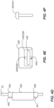
- FIGs. 6A-6D are schematic pictorial illustrations showing an electrode 626 having an extension 634 with a compressible base, in accordance with the disclosed technology.
- the electrode 626 can act as its own pin and rivet, as the extension 634 can be inserted into a spine attachment 622 of the spine 22 and then compressed to secure the electrode 626.
- the spine attachment 622 can be an aperture, such that an end 650 of the extension 634 can be inserted into the aperture, and then the end 650 of the extension 634 can be compressed to form a compressed base 654, in a manner similar to the second head 554 of the rivet described above.
- FIG. 6A shows an electrode 626 with an extension 634 being compressed.
- FIG. 6B shows the electrode 626 secured to a spine 622 by the end of the extension 634 being compressed into a compressed base 654 onto the spine 22.
- the spine attachment 622 can be a slot 624 extending a length L4 along the length L1 of the spine 22.
- the extension 634 of the electrode 626 can have a rectangular cross section with a width 660 that matches a width 662 of the slot 624.
- the extension 634 can be inserted into an end of the slot 624 and then slid to the desired location along the length L1 of the spine, and then the extension 634 can be compressed to secure the electrode 626 to the spine 22 at that location.
- the end 650 of the extension 634 can have a larger footprint, or a larger width 664, than the remainder of the extension 634. As such, the extension 634 can be constrained within the slot 624 as it slides to its location along the spine 22.
- FIG. 7 is a flowchart illustrating a method 700 of attaching an electrode (e.g., electrode 26, 326, 426, and/or 526) to an elongated member, in accordance with an embodiment of the present invention.
- the method 700 can include placing 702 a first electrode at an end of the elongated member.
- the elongated member can be, for example, any of the spines 22 described herein.
- placing the first electrode at the end of the member can include placing the end of the member into a slot (e.g., spine slot 332) of the first electrode.
- the member can be slidable through the slot.
- the method 700 can include sliding 704 the first electrode along a length of the member until a first electrode aperture of the first electrode aligns with a first aperture of the member.
- the method 700 can include inserting 706 a first pin (e.g., pin 350, pins 450/451, and/or rivet 550) into the first electrode aperture and the first aperture to affix the first electrode to the member.
- a first pin e.g., pin 350, pins 450/451, and/or rivet 550
- the method 700 can end after the inserting step 706. In other examples, additional steps can be performed according to the examples described herein.
- the method 700 can include inserting a second pin into a second electrode aperture and a second aperture to affix the first electrode to the member via another pin.
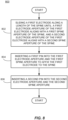
- FIG. 8 is a flowchart illustrating a method 800 of attaching an electrode (e.g., electrode 26, 326, 426, and/or 526) to a spine (e.g., spine 22) of a basket catheter, in accordance with an embodiment of the present invention.
- the method 800 can include sliding 802 a first electrode along a length (e.g., L1) of the spine until (i) a first electrode aperture (e.g., 428) of the first electrode aligns with a first spine aperture (e.g., 422) of the spine, and (ii) a second electrode aperture (e.g., 429) of the first electrode aligns with a second spine aperture (e.g., 423) of the spine.
- a first electrode aperture e.g., 428
- a second electrode aperture e.g., 429
- the electrode 428 can include tabs that include the electrode apertures (e.g., first tab 434 and second tab 436).
- sliding 802 the first electrode along a length of the spine can include sliding the electrode until (i) the first electrode aperture on the first tab 434 aligns with the first spine aperture, and the second electrode aperture on the second tab 436 aligns with the first spine aperture.
- the method 800 can include inserting 804 a first pin (e.g., pin 350, pin 450, and/or rivet 550) into the first electrode aperture and the first spine aperture to affix the first electrode to the spine.
- the method 800 can include inserting 806 a second pin (e.g., pin 350, pin 451, and/or rivet 550) into the second electrode aperture and the second spine aperture.
- the method 800 can end after the inserting step 806. In other examples, additional steps can be performed according to the examples described herein.
- the method 800 can include sliding a second electrode along the length of the spine until (iii) a third electrode aperture of the second electrode aligns with a third spine aperture of the spine and (iv) a fourth electrode aperture of the second electrode aligns with a fourth spine aperture of the spine.
- the method 800 can further include inserting a third pin into the third electrode aperture and the third spine aperture to affix the second electrode to the spine (e.g., step 804 can be repeated for the second electrode).
- the method 800 can further include inserting a fourth pin into the fourth electrode aperture and the fourth spine aperture to affix the second electrode to the spine (e.g., step 806 can be repeated for the second electrode).
- FIG. 9 is a flowchart illustrating a method 900 of securing an electrode (e.g., electrode 26, 326, 426, and/or 526) to an elongated member, in accordance with an embodiment of the present invention.
- This method 900 can be performed to secure an electrode using tabs (e.g., first tab 434 and second tab 436) that are separate from the electrode.
- the method 900 can include sliding 902 a first tab along a length of a spine until a first electrode aperture of the first tab aligns with a first spine aperture of the spine.
- the method 900 can include inserting 904 a first pin into the first electrode aperture and the first spine aperture to affix the first tab to the spine.
- the method 900 can include sliding 906 a first electrode along the length of the spine until the first electrode contacts the first tab.
- the method 900 can include sliding 908 a second tab along the length of the spine until a second electrode aperture of the second tab aligns with a second spine aperture of the spine.
- the method 900 can include inserting 910 a second pin into the second electrode aperture and the second spine aperture to affix the second tab to the spine.
- FIG. 10 is a flowchart illustrating a method 1000 of attaching an electrode (e.g., electrode 26, 326, 426, and/or 526) to a spine (e.g., spine 22) of a basket catheter, in accordance with an embodiment of the present invention.
- the method 1000 can include sliding 1002 a first electrode along a length of the spine until a first electrode aperture of the first electrode aligns with a first spine aperture of the spine.
- the method 1000 can include inserting 1004 a first rivet (e.g., rivet 550) into the first electrode aperture and the first spine aperture.
- the method 1000 can include riveting 1006 the first rivet to affix the first electrode to the spine.
- the method 1000 can end after the riveting step 1006. In other examples, additional steps can be performed according to the examples described herein.
- FIG. 11 is a flowchart illustrating a method 1100 of securing an electrode (e.g., electrode 26, 326, 426, 526, and/or 626) to an elongated member, in accordance with an embodiment of the present invention.
- the method 1100 can include sliding 1102 a first electrode along a length of a spine until it reaches a spine attachment on the spine.
- the spine attachment can be a single aperture along the length of the spine.
- the spine attachment can be slot, or track, along the length of the spine, and the spine attachment can be a position along the length of the slot, including at the end or any position along the length of the slot.
- the method 1100 can include compressing 1104 an extension of the first electrode to form a compressed base at an end of the extension, thereby securing the first electrode to the spine at a location of the spine attachment.
Landscapes
- Health & Medical Sciences (AREA)
- Life Sciences & Earth Sciences (AREA)
- Surgery (AREA)
- Engineering & Computer Science (AREA)
- Medical Informatics (AREA)
- General Health & Medical Sciences (AREA)
- Biomedical Technology (AREA)
- Heart & Thoracic Surgery (AREA)
- Nuclear Medicine, Radiotherapy & Molecular Imaging (AREA)
- Molecular Biology (AREA)
- Animal Behavior & Ethology (AREA)
- Otolaryngology (AREA)
- Public Health (AREA)
- Veterinary Medicine (AREA)
- Physics & Mathematics (AREA)
- Plasma & Fusion (AREA)
- Cardiology (AREA)
- Measurement And Recording Of Electrical Phenomena And Electrical Characteristics Of The Living Body (AREA)
- Surgical Instruments (AREA)
Applications Claiming Priority (2)
| Application Number | Priority Date | Filing Date | Title |
|---|---|---|---|
| US202363514504P | 2023-07-19 | 2023-07-19 | |
| US18/747,119 US20250025230A1 (en) | 2023-07-19 | 2024-06-18 | Electrode attachments for basket catheters |
Publications (1)
| Publication Number | Publication Date |
|---|---|
| EP4494589A1 true EP4494589A1 (fr) | 2025-01-22 |
Family
ID=91959503
Family Applications (1)
| Application Number | Title | Priority Date | Filing Date |
|---|---|---|---|
| EP24189332.0A Pending EP4494589A1 (fr) | 2023-07-19 | 2024-07-18 | Fixations d'électrode pour cathéters à panier |
Country Status (5)
| Country | Link |
|---|---|
| US (1) | US20250025230A1 (fr) |
| EP (1) | EP4494589A1 (fr) |
| JP (1) | JP2025015492A (fr) |
| CN (1) | CN119326498A (fr) |
| IL (1) | IL314356A (fr) |
Cited By (1)
| Publication number | Priority date | Publication date | Assignee | Title |
|---|---|---|---|---|
| EP4678129A1 (fr) * | 2024-07-10 | 2026-01-14 | Biosense Webster (Israel) Ltd. | Électrode ayant des éléments de retenue à utiliser avec une sonde médicale |
Citations (26)
| Publication number | Priority date | Publication date | Assignee | Title |
|---|---|---|---|---|
| US5391199A (en) | 1993-07-20 | 1995-02-21 | Biosense, Inc. | Apparatus and method for treating cardiac arrhythmias |
| US5509419A (en) * | 1992-09-25 | 1996-04-23 | Ep Technologies, Inc. | Cardiac mapping and ablation systems |
| US5558091A (en) | 1993-10-06 | 1996-09-24 | Biosense, Inc. | Magnetic determination of position and orientation |
| US6172499B1 (en) | 1999-10-29 | 2001-01-09 | Ascension Technology Corporation | Eddy current error-reduced AC magnetic position measurement system |
| US6239724B1 (en) | 1997-12-30 | 2001-05-29 | Remon Medical Technologies, Ltd. | System and method for telemetrically providing intrabody spatial position |
| US6332089B1 (en) | 1996-02-15 | 2001-12-18 | Biosense, Inc. | Medical procedures and apparatus using intrabody probes |
| US6484118B1 (en) | 2000-07-20 | 2002-11-19 | Biosense, Inc. | Electromagnetic position single axis system |
| US6618612B1 (en) | 1996-02-15 | 2003-09-09 | Biosense, Inc. | Independently positionable transducers for location system |
| US6690963B2 (en) | 1995-01-24 | 2004-02-10 | Biosense, Inc. | System for determining the location and orientation of an invasive medical instrument |
| US6892091B1 (en) | 2000-02-18 | 2005-05-10 | Biosense, Inc. | Catheter, method and apparatus for generating an electrical map of a chamber of the heart |
| EP1135078B1 (fr) * | 1998-12-02 | 2005-11-16 | C.R. Bard Inc. | Mecanisme interne pour deplacer une electrode coulissante |
| US7536218B2 (en) | 2005-07-15 | 2009-05-19 | Biosense Webster, Inc. | Hybrid magnetic-based and impedance-based position sensing |
| US7756576B2 (en) | 2005-08-26 | 2010-07-13 | Biosense Webster, Inc. | Position sensing and detection of skin impedance |
| US7848787B2 (en) | 2005-07-08 | 2010-12-07 | Biosense Webster, Inc. | Relative impedance measurement |
| US7869865B2 (en) | 2005-01-07 | 2011-01-11 | Biosense Webster, Inc. | Current-based position sensing |
| US8456182B2 (en) | 2008-09-30 | 2013-06-04 | Biosense Webster, Inc. | Current localization tracker |
| US20190069949A1 (en) * | 2014-12-03 | 2019-03-07 | Metavention, Inc. | Systems and methods for modulatng nerves or other tissue |
| US20200000518A1 (en) * | 2018-06-29 | 2020-01-02 | Biosense Webster (Israel) Ltd. | Catheter with mechanically expandable element having flex circuit |
| US20210161592A1 (en) | 2019-12-03 | 2021-06-03 | Biosense Webster (Israel) Ltd. | Pulse Generator for Irreversible Electroporation |
| US20210162210A1 (en) | 2019-12-03 | 2021-06-03 | Biosense Webster (Israel) Ltd. | Using reversible electroporation on cardiac tissue |
| US20210169568A1 (en) | 2019-12-09 | 2021-06-10 | Biosense Webster (Israel) Ltd. | Oriented irreversible-electroporation (ire) pulses to compensate for cell size and orientation |
| US20210169567A1 (en) | 2019-12-09 | 2021-06-10 | Biosense Webster (Israel) Ltd. | Irreversible-electroporation (ire) balloon catheter with membrane-insulated high-voltage balloon wires |
| US20210169550A1 (en) | 2019-12-05 | 2021-06-10 | Biosense Webster (Israel) Ltd. | Generating and interleaving of irreversible-electroporation and radiofrequnecy ablation (ire/rfa) waveforms |
| US20210177503A1 (en) | 2019-12-11 | 2021-06-17 | Biosense Webster (Israel) Ltd. | Regulating delivery of irreversible electroporation pulses according to transferred energy |
| US20210186604A1 (en) | 2019-12-24 | 2021-06-24 | Biosense Webster (Israel) Ltd. | Irreversible electroporation (ire) based on field, contact force and time |
| US20210196372A1 (en) | 2019-12-31 | 2021-07-01 | Biosense Webster (Israel) Ltd. | Using irrigation on irreversible-electroporation (ire) electrodes to prevent arcing |
Family Cites Families (1)
| Publication number | Priority date | Publication date | Assignee | Title |
|---|---|---|---|---|
| EP3836859B1 (fr) * | 2018-08-13 | 2025-03-05 | Cardionomic, Inc. | Systèmes pour affecter la contractilité et/ou la relaxation cardiaques |
-
2024
- 2024-06-18 US US18/747,119 patent/US20250025230A1/en active Pending
- 2024-07-16 IL IL314356A patent/IL314356A/en unknown
- 2024-07-18 JP JP2024114605A patent/JP2025015492A/ja active Pending
- 2024-07-18 EP EP24189332.0A patent/EP4494589A1/fr active Pending
- 2024-07-18 CN CN202410963956.5A patent/CN119326498A/zh active Pending
Patent Citations (28)
| Publication number | Priority date | Publication date | Assignee | Title |
|---|---|---|---|---|
| US5509419A (en) * | 1992-09-25 | 1996-04-23 | Ep Technologies, Inc. | Cardiac mapping and ablation systems |
| US5443489A (en) | 1993-07-20 | 1995-08-22 | Biosense, Inc. | Apparatus and method for ablation |
| US5391199A (en) | 1993-07-20 | 1995-02-21 | Biosense, Inc. | Apparatus and method for treating cardiac arrhythmias |
| US5558091A (en) | 1993-10-06 | 1996-09-24 | Biosense, Inc. | Magnetic determination of position and orientation |
| US6690963B2 (en) | 1995-01-24 | 2004-02-10 | Biosense, Inc. | System for determining the location and orientation of an invasive medical instrument |
| US6332089B1 (en) | 1996-02-15 | 2001-12-18 | Biosense, Inc. | Medical procedures and apparatus using intrabody probes |
| US6618612B1 (en) | 1996-02-15 | 2003-09-09 | Biosense, Inc. | Independently positionable transducers for location system |
| US6788967B2 (en) | 1997-05-14 | 2004-09-07 | Biosense, Inc. | Medical diagnosis, treatment and imaging systems |
| US6239724B1 (en) | 1997-12-30 | 2001-05-29 | Remon Medical Technologies, Ltd. | System and method for telemetrically providing intrabody spatial position |
| EP1135078B1 (fr) * | 1998-12-02 | 2005-11-16 | C.R. Bard Inc. | Mecanisme interne pour deplacer une electrode coulissante |
| US6172499B1 (en) | 1999-10-29 | 2001-01-09 | Ascension Technology Corporation | Eddy current error-reduced AC magnetic position measurement system |
| US6892091B1 (en) | 2000-02-18 | 2005-05-10 | Biosense, Inc. | Catheter, method and apparatus for generating an electrical map of a chamber of the heart |
| US6484118B1 (en) | 2000-07-20 | 2002-11-19 | Biosense, Inc. | Electromagnetic position single axis system |
| US7869865B2 (en) | 2005-01-07 | 2011-01-11 | Biosense Webster, Inc. | Current-based position sensing |
| US7848787B2 (en) | 2005-07-08 | 2010-12-07 | Biosense Webster, Inc. | Relative impedance measurement |
| US7536218B2 (en) | 2005-07-15 | 2009-05-19 | Biosense Webster, Inc. | Hybrid magnetic-based and impedance-based position sensing |
| US7756576B2 (en) | 2005-08-26 | 2010-07-13 | Biosense Webster, Inc. | Position sensing and detection of skin impedance |
| US8456182B2 (en) | 2008-09-30 | 2013-06-04 | Biosense Webster, Inc. | Current localization tracker |
| US20190069949A1 (en) * | 2014-12-03 | 2019-03-07 | Metavention, Inc. | Systems and methods for modulatng nerves or other tissue |
| US20200000518A1 (en) * | 2018-06-29 | 2020-01-02 | Biosense Webster (Israel) Ltd. | Catheter with mechanically expandable element having flex circuit |
| US20210161592A1 (en) | 2019-12-03 | 2021-06-03 | Biosense Webster (Israel) Ltd. | Pulse Generator for Irreversible Electroporation |
| US20210162210A1 (en) | 2019-12-03 | 2021-06-03 | Biosense Webster (Israel) Ltd. | Using reversible electroporation on cardiac tissue |
| US20210169550A1 (en) | 2019-12-05 | 2021-06-10 | Biosense Webster (Israel) Ltd. | Generating and interleaving of irreversible-electroporation and radiofrequnecy ablation (ire/rfa) waveforms |
| US20210169568A1 (en) | 2019-12-09 | 2021-06-10 | Biosense Webster (Israel) Ltd. | Oriented irreversible-electroporation (ire) pulses to compensate for cell size and orientation |
| US20210169567A1 (en) | 2019-12-09 | 2021-06-10 | Biosense Webster (Israel) Ltd. | Irreversible-electroporation (ire) balloon catheter with membrane-insulated high-voltage balloon wires |
| US20210177503A1 (en) | 2019-12-11 | 2021-06-17 | Biosense Webster (Israel) Ltd. | Regulating delivery of irreversible electroporation pulses according to transferred energy |
| US20210186604A1 (en) | 2019-12-24 | 2021-06-24 | Biosense Webster (Israel) Ltd. | Irreversible electroporation (ire) based on field, contact force and time |
| US20210196372A1 (en) | 2019-12-31 | 2021-07-01 | Biosense Webster (Israel) Ltd. | Using irrigation on irreversible-electroporation (ire) electrodes to prevent arcing |
Cited By (1)
| Publication number | Priority date | Publication date | Assignee | Title |
|---|---|---|---|---|
| EP4678129A1 (fr) * | 2024-07-10 | 2026-01-14 | Biosense Webster (Israel) Ltd. | Électrode ayant des éléments de retenue à utiliser avec une sonde médicale |
Also Published As
| Publication number | Publication date |
|---|---|
| IL314356A (en) | 2025-02-01 |
| CN119326498A (zh) | 2025-01-21 |
| JP2025015492A (ja) | 2025-01-30 |
| US20250025230A1 (en) | 2025-01-23 |
Similar Documents
| Publication | Publication Date | Title |
|---|---|---|
| US12484961B2 (en) | Mechanical retainer systems for electrodes of a basket catheter, and methods of the same | |
| EP4393430A1 (fr) | Systèmes et procédés pour cathéter de cartographie de cage cylindrique et d'ablation ayant des circuits flexibles | |
| EP4494589A1 (fr) | Fixations d'électrode pour cathéters à panier | |
| EP4393427B1 (fr) | Système de traitement en forme de cage cylindrique pour un contact de tissu distribué pendant la cartographie et l'ablation | |
| EP4393428A1 (fr) | Capteurs de force de contact pour cathéters à panier et leurs procédés d'utilisation | |
| EP4382061A1 (fr) | Capteurs de force pour catheters a panier | |
| EP4382060B1 (fr) | Electrodes pour catheters a panier | |
| EP4464270A1 (fr) | Electrodes et configurations d'electrodes pour un catheter a panier | |
| EP4473928A1 (fr) | Ensembles panier extensibles et ensembles panier extensibles avec soulagement de contrainte de fil d'électrode | |
| EP4527332A1 (fr) | Dispositif médical avec une structure vertébrale monolithique | |
| EP4678129A1 (fr) | Électrode ayant des éléments de retenue à utiliser avec une sonde médicale | |
| US20240216055A1 (en) | Fractal cylindrical cage systems and methods for distributed tissue contact for mapping and ablation | |
| US20250099160A1 (en) | Medical device with an end effector including connecting hubs and an electrode array | |
| EP4520283A2 (fr) | Dispositif médical avec un panier et un logement | |
| EP4393425A1 (fr) | Panier d'électrode à colonne déformée et ses procédés | |
| CN118141505A (zh) | 用于篮式导管的电极 |
Legal Events
| Date | Code | Title | Description |
|---|---|---|---|
| PUAI | Public reference made under article 153(3) epc to a published international application that has entered the european phase |
Free format text: ORIGINAL CODE: 0009012 |
|
| STAA | Information on the status of an ep patent application or granted ep patent |
Free format text: STATUS: THE APPLICATION HAS BEEN PUBLISHED |
|
| AK | Designated contracting states |
Kind code of ref document: A1 Designated state(s): AL AT BE BG CH CY CZ DE DK EE ES FI FR GB GR HR HU IE IS IT LI LT LU LV MC ME MK MT NL NO PL PT RO RS SE SI SK SM TR |
|
| STAA | Information on the status of an ep patent application or granted ep patent |
Free format text: STATUS: REQUEST FOR EXAMINATION WAS MADE |
|
| 17P | Request for examination filed |
Effective date: 20250721 |