EP4494795A1 - Brasage par faisceau d'électrons pour réparer un composant - Google Patents
Brasage par faisceau d'électrons pour réparer un composant Download PDFInfo
- Publication number
- EP4494795A1 EP4494795A1 EP24185555.0A EP24185555A EP4494795A1 EP 4494795 A1 EP4494795 A1 EP 4494795A1 EP 24185555 A EP24185555 A EP 24185555A EP 4494795 A1 EP4494795 A1 EP 4494795A1
- Authority
- EP
- European Patent Office
- Prior art keywords
- component
- braze
- area
- powder
- braze material
- Prior art date
- Legal status (The legal status is an assumption and is not a legal conclusion. Google has not performed a legal analysis and makes no representation as to the accuracy of the status listed.)
- Pending
Links
Images



Classifications
-
- B—PERFORMING OPERATIONS; TRANSPORTING
- B23—MACHINE TOOLS; METAL-WORKING NOT OTHERWISE PROVIDED FOR
- B23K—SOLDERING OR UNSOLDERING; WELDING; CLADDING OR PLATING BY SOLDERING OR WELDING; CUTTING BY APPLYING HEAT LOCALLY, e.g. FLAME CUTTING; WORKING BY LASER BEAM
- B23K1/00—Soldering, e.g. brazing, or unsoldering
- B23K1/005—Soldering by means of radiant energy
- B23K1/0056—Soldering by means of radiant energy soldering by means of beams, e.g. lasers, electron beams [EB]
-
- B—PERFORMING OPERATIONS; TRANSPORTING
- B23—MACHINE TOOLS; METAL-WORKING NOT OTHERWISE PROVIDED FOR
- B23K—SOLDERING OR UNSOLDERING; WELDING; CLADDING OR PLATING BY SOLDERING OR WELDING; CUTTING BY APPLYING HEAT LOCALLY, e.g. FLAME CUTTING; WORKING BY LASER BEAM
- B23K1/00—Soldering, e.g. brazing, or unsoldering
- B23K1/0008—Soldering, e.g. brazing, or unsoldering specially adapted for particular articles or work
- B23K1/0018—Brazing of turbine parts
-
- B—PERFORMING OPERATIONS; TRANSPORTING
- B22—CASTING; POWDER METALLURGY
- B22F—WORKING METALLIC POWDER; MANUFACTURE OF ARTICLES FROM METALLIC POWDER; MAKING METALLIC POWDER; APPARATUS OR DEVICES SPECIALLY ADAPTED FOR METALLIC POWDER
- B22F10/00—Additive manufacturing of workpieces or articles from metallic powder
- B22F10/20—Direct sintering or melting
- B22F10/28—Powder bed fusion, e.g. selective laser melting [SLM] or electron beam melting [EBM]
-
- B—PERFORMING OPERATIONS; TRANSPORTING
- B22—CASTING; POWDER METALLURGY
- B22F—WORKING METALLIC POWDER; MANUFACTURE OF ARTICLES FROM METALLIC POWDER; MAKING METALLIC POWDER; APPARATUS OR DEVICES SPECIALLY ADAPTED FOR METALLIC POWDER
- B22F10/00—Additive manufacturing of workpieces or articles from metallic powder
- B22F10/60—Treatment of workpieces or articles after build-up
- B22F10/64—Treatment of workpieces or articles after build-up by thermal means
-
- B—PERFORMING OPERATIONS; TRANSPORTING
- B22—CASTING; POWDER METALLURGY
- B22F—WORKING METALLIC POWDER; MANUFACTURE OF ARTICLES FROM METALLIC POWDER; MAKING METALLIC POWDER; APPARATUS OR DEVICES SPECIALLY ADAPTED FOR METALLIC POWDER
- B22F3/00—Manufacture of workpieces or articles from metallic powder characterised by the manner of compacting or sintering; Apparatus specially adapted therefor ; Presses and furnaces
- B22F3/10—Sintering only
- B22F3/105—Sintering only by using electric current other than for infrared radiant energy, laser radiation or plasma ; by ultrasonic bonding
-
- B—PERFORMING OPERATIONS; TRANSPORTING
- B22—CASTING; POWDER METALLURGY
- B22F—WORKING METALLIC POWDER; MANUFACTURE OF ARTICLES FROM METALLIC POWDER; MAKING METALLIC POWDER; APPARATUS OR DEVICES SPECIALLY ADAPTED FOR METALLIC POWDER
- B22F5/00—Manufacture of workpieces or articles from metallic powder characterised by the special shape of the product
- B22F5/04—Manufacture of workpieces or articles from metallic powder characterised by the special shape of the product of turbine blades
-
- B—PERFORMING OPERATIONS; TRANSPORTING
- B23—MACHINE TOOLS; METAL-WORKING NOT OTHERWISE PROVIDED FOR
- B23K—SOLDERING OR UNSOLDERING; WELDING; CLADDING OR PLATING BY SOLDERING OR WELDING; CUTTING BY APPLYING HEAT LOCALLY, e.g. FLAME CUTTING; WORKING BY LASER BEAM
- B23K1/00—Soldering, e.g. brazing, or unsoldering
- B23K1/008—Soldering within a furnace
-
- B—PERFORMING OPERATIONS; TRANSPORTING
- B23—MACHINE TOOLS; METAL-WORKING NOT OTHERWISE PROVIDED FOR
- B23K—SOLDERING OR UNSOLDERING; WELDING; CLADDING OR PLATING BY SOLDERING OR WELDING; CUTTING BY APPLYING HEAT LOCALLY, e.g. FLAME CUTTING; WORKING BY LASER BEAM
- B23K35/00—Rods, electrodes, materials, or media, for use in soldering, welding, or cutting
- B23K35/02—Rods, electrodes, materials, or media, for use in soldering, welding, or cutting characterised by mechanical features, e.g. shape
- B23K35/0222—Rods, electrodes, materials, or media, for use in soldering, welding, or cutting characterised by mechanical features, e.g. shape for use in soldering or brazing
- B23K35/0244—Powders, particles or spheres; Preforms made therefrom
-
- B—PERFORMING OPERATIONS; TRANSPORTING
- B23—MACHINE TOOLS; METAL-WORKING NOT OTHERWISE PROVIDED FOR
- B23P—METAL-WORKING NOT OTHERWISE PROVIDED FOR; COMBINED OPERATIONS; UNIVERSAL MACHINE TOOLS
- B23P6/00—Restoring or reconditioning objects
- B23P6/002—Repairing turbine components, e.g. moving or stationary blades, rotors
- B23P6/005—Repairing turbine components, e.g. moving or stationary blades, rotors using only replacement pieces of a particular form
-
- B—PERFORMING OPERATIONS; TRANSPORTING
- B23—MACHINE TOOLS; METAL-WORKING NOT OTHERWISE PROVIDED FOR
- B23P—METAL-WORKING NOT OTHERWISE PROVIDED FOR; COMBINED OPERATIONS; UNIVERSAL MACHINE TOOLS
- B23P6/00—Restoring or reconditioning objects
- B23P6/002—Repairing turbine components, e.g. moving or stationary blades, rotors
- B23P6/007—Repairing turbine components, e.g. moving or stationary blades, rotors using only additive methods, e.g. build-up welding
-
- B—PERFORMING OPERATIONS; TRANSPORTING
- B33—ADDITIVE MANUFACTURING TECHNOLOGY
- B33Y—ADDITIVE MANUFACTURING, i.e. MANUFACTURING OF THREE-DIMENSIONAL [3D] OBJECTS BY ADDITIVE DEPOSITION, ADDITIVE AGGLOMERATION OR ADDITIVE LAYERING, e.g. BY 3D PRINTING, STEREOLITHOGRAPHY OR SELECTIVE LASER SINTERING
- B33Y10/00—Processes of additive manufacturing
-
- B—PERFORMING OPERATIONS; TRANSPORTING
- B33—ADDITIVE MANUFACTURING TECHNOLOGY
- B33Y—ADDITIVE MANUFACTURING, i.e. MANUFACTURING OF THREE-DIMENSIONAL [3D] OBJECTS BY ADDITIVE DEPOSITION, ADDITIVE AGGLOMERATION OR ADDITIVE LAYERING, e.g. BY 3D PRINTING, STEREOLITHOGRAPHY OR SELECTIVE LASER SINTERING
- B33Y40/00—Auxiliary operations or equipment, e.g. for material handling
- B33Y40/20—Post-treatment, e.g. curing, coating or polishing
-
- B—PERFORMING OPERATIONS; TRANSPORTING
- B33—ADDITIVE MANUFACTURING TECHNOLOGY
- B33Y—ADDITIVE MANUFACTURING, i.e. MANUFACTURING OF THREE-DIMENSIONAL [3D] OBJECTS BY ADDITIVE DEPOSITION, ADDITIVE AGGLOMERATION OR ADDITIVE LAYERING, e.g. BY 3D PRINTING, STEREOLITHOGRAPHY OR SELECTIVE LASER SINTERING
- B33Y80/00—Products made by additive manufacturing
-
- B—PERFORMING OPERATIONS; TRANSPORTING
- B22—CASTING; POWDER METALLURGY
- B22F—WORKING METALLIC POWDER; MANUFACTURE OF ARTICLES FROM METALLIC POWDER; MAKING METALLIC POWDER; APPARATUS OR DEVICES SPECIALLY ADAPTED FOR METALLIC POWDER
- B22F7/00—Manufacture of composite layers, workpieces, or articles, comprising metallic powder, by sintering the powder, with or without compacting wherein at least one part is obtained by sintering or compression
- B22F7/06—Manufacture of composite layers, workpieces, or articles, comprising metallic powder, by sintering the powder, with or without compacting wherein at least one part is obtained by sintering or compression of composite workpieces or articles from parts, e.g. to form tipped tools
- B22F7/062—Manufacture of composite layers, workpieces, or articles, comprising metallic powder, by sintering the powder, with or without compacting wherein at least one part is obtained by sintering or compression of composite workpieces or articles from parts, e.g. to form tipped tools involving the connection or repairing of preformed parts
- B22F2007/068—Manufacture of composite layers, workpieces, or articles, comprising metallic powder, by sintering the powder, with or without compacting wherein at least one part is obtained by sintering or compression of composite workpieces or articles from parts, e.g. to form tipped tools involving the connection or repairing of preformed parts repairing articles
-
- B—PERFORMING OPERATIONS; TRANSPORTING
- B23—MACHINE TOOLS; METAL-WORKING NOT OTHERWISE PROVIDED FOR
- B23K—SOLDERING OR UNSOLDERING; WELDING; CLADDING OR PLATING BY SOLDERING OR WELDING; CUTTING BY APPLYING HEAT LOCALLY, e.g. FLAME CUTTING; WORKING BY LASER BEAM
- B23K2101/00—Articles made by soldering, welding or cutting
- B23K2101/001—Turbines
Definitions
- This application relates to the use of electron beam additive manufacturing systems with braze materials to repair damage to components such as gas turbine engine airfoils.
- Gas turbine engine airfoils have complex shapes, and are subject to challenging environmental conditions. This can result in cracks or other damage. In addition, areas may wear over time. It is known to repair such airfoil using any number of techniques.
- brazing In brazing braze materials may be manually applied to fill the cracks or other surface irregularities, and then sintered into the component. More recently direct laser braze cladding has been proposed.
- Electron beam additive manufacturing is also known. However, it has typically been utilized with welding, which is not acceptable for certain parts due to the high temperatures.
- a method of repairing a component includes the steps of identifying a component to be repaired, and an area on the component in need of repair. Next, one places the component into a chamber, and deposits braze material at the area. Next, one applies an electron beam focused on a portion of the area to melt the braze material that has been deposited at the area. Finally, one places the component into a furnace to further melt and diffuse the braze powder into the component.
- Figure 1A shows a gas turbine engine component 20 which may have a radially outer platform 22 and a radially inner platform 24.
- Three airfoils 26 extend radially between the platforms 22 and 24. Airfoils 26 may be static vanes. It should be understood the teachings of this disclosure extend to repair of other components.
- FIG. 1B there is damage 34 such as a crack in a central airfoil 26.
- Each of the airfoils extend between a leading edge 30 and a trailing edge 32.
- the crack 34 would be difficult to access with several existing repair techniques. That is, many techniques require line of sight access to the area to be repaired. There will be no such access to crack 34.
- Figure 1C shows another type of damage in the nature of wear 36 into an airfoil 26. Again, particularly when in a component such as component 20, area 36 may be difficult to access.
- System 40 for repairing difficult to access areas is shown in Figure 2A .
- System 40 includes an electron beam additive manufacturing system, as is known. However, the use of the system 40 is unique to this disclosure.
- the electron beam additive manufacturing system includes an incandescent cathode 42.
- the cathode is positioned in a bias cup 44.
- Bias cup 44 is positioned above a primary anode 46.
- An electron beam 48 is shown expanding outwardly from the incandescent cathode 42. Beam 48 passes through a focusing coil 50, and as can be seen, at an apex 52 it begins to be focused as shown at 54 to a smaller area.
- the focused electron beam 54 passes through a deflection coil 53.
- the focused beam 54 is directed through an outer surface 58 of an airfoil 26 and to a focus point 56.
- the beam can pass through a body of the airfoil 26 such that focus point 56 can be set to crack 34 even though there is no line of sight access.
- the airfoil 26 could be a central airfoil such as in the component 20 of Figure 1B .
- the beam is focused within a vacuum chamber 60.
- a vibration bed 62 vibrates braze powder 64 to fill the crack or other damaged area on the airfoil 26.
- the use of the powder deposition through the vibration bed 62 may be as known.
- the component is illustrated as a static vane, the teachings of this disclosure would extend to other components having an airfoil such as blades, etc.
- the repair could be occurring at other areas of the component, such as the platforms.
- Figure 2B is a detail of Figure 2A and shows the crack 34 being filled with braze material and the subject of focus at point 56.
- Figure 3 shows an alternative embodiment 70 wherein the powder is deposited by a tool 72 movable within a vacuum chamber.
- Tool 72 is provided with two bins 74 and 76 of distinct braze material.
- the Figure 2A system could also be utilized with two distinct braze powders.
- the first braze powder 74 may be deposited on the component 26 to repair a first type of substrate defect such as, but not limited to, the crack 34.
- the second braze powder 76 may be deposited with the component 26 to repair a second type of substrate defect such as, but not limited to, the wear region 36 of Figure 1C .
- the first braze powder 74 may be provided (e.g., selected, formulated, etc.) for increased wettability, flowability and/or capillary penetration.
- the first braze powder may thereby be particularly suited for entering and filling voids.
- the second braze powder 76 may be provided (e.g., selected, formulated, etc.) for improved dimensional repair of the surface due to lower wettability and flowability.
- the second braze powder may thereby be particularly suited for forming claddings.
- first braze powder 74 and the second braze powder 76 may be mixed together in some proportion to provide a combined braze powder with intermediate braze properties.
- the two powders could be mixed might be to achieve various proportions of the two.
- a designer might want a high-flow, a moderate-flow or a stiff final deposited powder.
- the second braze powder 76 may include higher proportions of a metal alloy powder relative to a braze material powder (e.g., 70/30).
- the first braze powder 74 may include lower proportions of the metal alloy powder relative to the braze material powder (e.g., 30/70).
- the first braze powder 74 may include a mixture of metal alloy powder (e.g., substrate powder) and braze material powder.
- the metal alloy powder may be selected to have a relatively high melting point and common or similar material properties as the substrate of component 26, e.g., an aluminum (Al) superalloy, a nickel (Ni) superalloy, a titanium (Ti) superalloy, etc.
- the braze material powder may be selected to have a relatively low melting point, which is lower than the melting point of the metal alloy powder.
- the braze material powder may also include a common or similar base element as the substrate and/or the metal alloy powder (e.g., aluminum (Al), nickel (Ni) or titanium (Ti)) without the super alloying elements.
- the brazing material powder may also include boron (B), silicon (Si) and/or other melting point suppressants which may help facilitate melting and diffusion of the metal alloy powder with the substrate.
- B boron
- Si silicon
- the present disclosure is not limited to the foregoing exemplary braze materials.
- the second braze powder 76 may include a mixture of the metal alloy powder (e.g., substrate powder) and the braze material powder.
- a ratio of the metal alloy powder to the braze material powder in the second braze powder 76 may be greater than a ratio of the metal alloy powder to the braze material powder in the first braze powder 74.
- the second braze powder 76 may include higher proportions of the metal alloy powder relative to the braze material powder (e.g., 60/40).
- the first braze powder 74 may include lower proportions of the metal alloy powder relative to the braze material powder (e.g., 30/70).
- one or more or all of the constituent materials in the first braze powder may be different that one or more or all of the constituent materials in the second braze powder.
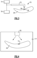
- Figure 4 shows a subsequent step after the braze material has been deposited to fill the crack and actuated by the electron beam to melt.
- the component is then placed within a vacuum furnace 77, and the material 74 is subject to high heat from a heating element 78.
- An example of the furnace may be vacuum pressure ranges as low as 0.1 micron and temperatures up to 2500 °F (about 1400 °C). Of course other furnace parameters may be used.
- FIG. 5 A flow chart for the method of this disclosure is illustrated in Figure 5 .
- a part to be repaired is received, stripped of coating and cleaned, etc.
- Plasma is a metal coating applied by a plasma arc spray used for surface build-up. It is a "band-aid" that must be removed prior to brazing. Plasma spray is a bonded coating. Diffused coatings and bonded coatings such as TBC and plasma must be removed before brazing.
- step 102 the area to be repaired on the part is identified.
- the low braze melt material (74) may be utilized with electron beam brazing.
- the higher melt brazing powder (76) may be utilized, again using electron beam brazing.
- step 108 the part is then placed into the vacuum furnace and ran through a melt/diffuse cycle.
- a method of repairing a component under this disclosure could be said to include the steps of identifying a component to be repaired, and an area 102 on the component in need of repair.
- one places the component into a chamber 60, and deposits braze material 104/106 into the area.
- one applies an electron beam 48 focused on a portion of the area to sinter the braze material that has been deposited at the area.
- one places the component into a furnace 77 to melt and diffuse the braze powder into the component 108.
- the furnace is a vacuum furnace.
- the chamber is a vacuum chamber.
- the component is placed within a bed of braze material 64 and subject to a vibration bed 62 to deposit the braze material at the area.
- the component has a plurality of airfoils 26, and the area 34 is at a location where there is no line of sight access to the area.
- two distinct braze materials 74/76 are deposited in distinct substeps of step 2.
- one of the two distinct braze materials includes a higher portion of a metal alloy based upon a metal alloy of the component, and a lower proportion of a braze material powder
- the other of the two distinct braze materials includes a lower proportion of the metal alloy powder based upon a metal alloy forming the component and a higher percentage of the braze material powder.
- the braze material is deposited from a deposit tool 72 onto the area to be repaired.
- the component has a plurality of airfoils 26, and the area 34 is at a location where there is no line of sight access to the area.
- two distinct braze materials 74/76 are deposited in distinct substeps of step 2) and one of two includes a higher portion of a metal alloy based upon a metal alloy of the component, and a lower proportion of a braze material powder, and an other of the two distinct braze materials includes a lower proportion of the metal alloy powder based upon a metal alloy forming the component and a higher percentage of the braze material powder.
- the chamber is a vacuum chamber.
- the component is placed within a bed of braze material 64 and subject to a vibration bed 62 to deposit the braze material at the area.
- the component has a plurality of airfoils 26, and the area 34 is at a location where there is no line of sight access to the area.
- two distinct braze materials 74/76 are deposited in distinct substeps of step 2) and one of two includes a higher portion of a metal alloy based upon a metal alloy of the component, and a lower proportion of a braze material powder, and an other of the two distinct braze materials includes a lower proportion of the metal alloy powder based upon a metal alloy forming the component and a higher percentage of the braze material powder.
- the braze material is deposited from a deposit tool 72 onto the area to be repaired.
- the component has a plurality of airfoils 26, and the area 34 is at a location where there is no line of sight access to the area.
- the component is placed within a bed of braze material 64 and subject to a vibration bed 62 to deposit the braze material at the area.
- the braze material is deposited from a deposit tool 72 onto the area to be repaired.
- the component has a plurality of airfoils 26, and the area 34 is at a location where there is no line of sight access to the area.
- two distinct braze materials 74/76 are deposited in distinct substeps of step 2) and one of two includes a higher portion of a metal alloy based upon a metal alloy of the component, and a lower proportion of a braze material powder, and an other of the two distinct braze materials includes a lower proportion of the metal alloy powder based upon a metal alloy forming the component and a higher percentage of the braze material powder.
Landscapes
- Engineering & Computer Science (AREA)
- Mechanical Engineering (AREA)
- Manufacturing & Machinery (AREA)
- Chemical & Material Sciences (AREA)
- Materials Engineering (AREA)
- Physics & Mathematics (AREA)
- Optics & Photonics (AREA)
- Thermal Sciences (AREA)
- Plasma & Fusion (AREA)
- Turbine Rotor Nozzle Sealing (AREA)
- Welding Or Cutting Using Electron Beams (AREA)
- Powder Metallurgy (AREA)
Applications Claiming Priority (1)
| Application Number | Priority Date | Filing Date | Title |
|---|---|---|---|
| US18/343,074 US20250001511A1 (en) | 2023-06-28 | 2023-06-28 | Electron beam brazing to repair component |
Publications (1)
| Publication Number | Publication Date |
|---|---|
| EP4494795A1 true EP4494795A1 (fr) | 2025-01-22 |
Family
ID=91738917
Family Applications (1)
| Application Number | Title | Priority Date | Filing Date |
|---|---|---|---|
| EP24185555.0A Pending EP4494795A1 (fr) | 2023-06-28 | 2024-06-28 | Brasage par faisceau d'électrons pour réparer un composant |
Country Status (3)
| Country | Link |
|---|---|
| US (1) | US20250001511A1 (fr) |
| EP (1) | EP4494795A1 (fr) |
| CA (1) | CA3244455A1 (fr) |
Citations (2)
| Publication number | Priority date | Publication date | Assignee | Title |
|---|---|---|---|---|
| US20170297101A1 (en) * | 2016-04-19 | 2017-10-19 | MTU Aero Engines AG | Method and device for manufacturing at least a portion of a component |
| US20170320174A1 (en) * | 2014-11-14 | 2017-11-09 | Safran Aircraft Engines | Method for producing a turbine engine part |
Family Cites Families (3)
| Publication number | Priority date | Publication date | Assignee | Title |
|---|---|---|---|---|
| WO2021021231A1 (fr) * | 2019-07-30 | 2021-02-04 | Siemens Energy, Inc. | Système et procédé de réparation de composants de turbine à gaz à haute température |
| US11795832B2 (en) * | 2019-11-13 | 2023-10-24 | Siemens Energy, Inc. | System and method for repairing high-temperature gas turbine components |
| US11565336B2 (en) * | 2019-11-15 | 2023-01-31 | Rolls-Royce North American Technologies Inc. | Method of selectively bonding braze powders to a surface |
-
2023
- 2023-06-28 US US18/343,074 patent/US20250001511A1/en active Pending
-
2024
- 2024-06-26 CA CA3244455A patent/CA3244455A1/en active Pending
- 2024-06-28 EP EP24185555.0A patent/EP4494795A1/fr active Pending
Patent Citations (2)
| Publication number | Priority date | Publication date | Assignee | Title |
|---|---|---|---|---|
| US20170320174A1 (en) * | 2014-11-14 | 2017-11-09 | Safran Aircraft Engines | Method for producing a turbine engine part |
| US20170297101A1 (en) * | 2016-04-19 | 2017-10-19 | MTU Aero Engines AG | Method and device for manufacturing at least a portion of a component |
Also Published As
| Publication number | Publication date |
|---|---|
| US20250001511A1 (en) | 2025-01-02 |
| CA3244455A1 (en) | 2025-06-06 |
Similar Documents
| Publication | Publication Date | Title |
|---|---|---|
| US11077512B2 (en) | Manufactured article and method | |
| US7966707B2 (en) | Method for repairing superalloy components using inserts | |
| AU649926B2 (en) | Powder metallurgy repair technique | |
| US10987900B2 (en) | Article | |
| JP6595593B2 (ja) | タービンエンジン部品の製造方法 | |
| US20040086635A1 (en) | Method of repairing a stationary shroud of a gas turbine engine using laser cladding | |
| US20060248718A1 (en) | Superalloy repair methods and inserts | |
| US20070044306A1 (en) | Superalloy repair methods | |
| EP4335574A1 (fr) | Dépôt adaptatif de matériau de brasage à l'aide de données de balayage de lumière structurée | |
| EP4335571A1 (fr) | Dépôt additif de multiples matériaux de brasure | |
| US11753724B2 (en) | Methods of forming desired geometry on superalloy part using powder mixture of low and high melt temperature superalloys | |
| EP4494795A1 (fr) | Brasage par faisceau d'électrons pour réparer un composant | |
| EP4599977A1 (fr) | Microstructure modifiée pour améliorer les performances pendant un processus de réparation de dépôt d'énergie dirigée | |
| RU2281845C1 (ru) | Способ ремонта поверхностных дефектов изделий гтд | |
| EP4299237A1 (fr) | Procédé et système de projection thermique de matériaux d'alliage de brasage sur un composant à base de nickel pour faciliter un joint brasé haute densité à faibles discontinuités | |
| CN111872628A (zh) | 使用相凝聚修复高温合金组件的方法 | |
| JP7068153B2 (ja) | タービン部品の補修方法および補修されたタービン部品の製造方法 | |
| US20210205911A1 (en) | Method of diffusion bonding utilizing vapor deposition | |
| US20240082940A1 (en) | Additively depositing braze material | |
| EP4592008A1 (fr) | Utilisation d'une surface sacrificielle pendant un processus de réparation par dépôt d'énergie dirigée | |
| US20250242945A1 (en) | Engineered residual stress state for enhanced performance during directed energy deposition repair process | |
| EP4424457A2 (fr) | Réparation adaptative avec deux matériaux de brasage et balayages de lumière structurés | |
| RU2556175C1 (ru) | Способ восстановления профиля пера лопатки газотурбинного двигателя |
Legal Events
| Date | Code | Title | Description |
|---|---|---|---|
| PUAI | Public reference made under article 153(3) epc to a published international application that has entered the european phase |
Free format text: ORIGINAL CODE: 0009012 |
|
| STAA | Information on the status of an ep patent application or granted ep patent |
Free format text: STATUS: THE APPLICATION HAS BEEN PUBLISHED |
|
| AK | Designated contracting states |
Kind code of ref document: A1 Designated state(s): AL AT BE BG CH CY CZ DE DK EE ES FI FR GB GR HR HU IE IS IT LI LT LU LV MC ME MK MT NL NO PL PT RO RS SE SI SK SM TR |
|
| STAA | Information on the status of an ep patent application or granted ep patent |
Free format text: STATUS: REQUEST FOR EXAMINATION WAS MADE |
|
| 17P | Request for examination filed |
Effective date: 20250721 |