EP4494801A1 - Commande d'un système optique d'une machine de découpe au laser pour compenser la dérive thermique - Google Patents
Commande d'un système optique d'une machine de découpe au laser pour compenser la dérive thermique Download PDFInfo
- Publication number
- EP4494801A1 EP4494801A1 EP23186329.1A EP23186329A EP4494801A1 EP 4494801 A1 EP4494801 A1 EP 4494801A1 EP 23186329 A EP23186329 A EP 23186329A EP 4494801 A1 EP4494801 A1 EP 4494801A1
- Authority
- EP
- European Patent Office
- Prior art keywords
- focus position
- optical system
- optical signals
- drift
- optical
- Prior art date
- Legal status (The legal status is an assumption and is not a legal conclusion. Google has not performed a legal analysis and makes no representation as to the accuracy of the status listed.)
- Withdrawn
Links
Images


Classifications
-
- B—PERFORMING OPERATIONS; TRANSPORTING
- B23—MACHINE TOOLS; METAL-WORKING NOT OTHERWISE PROVIDED FOR
- B23K—SOLDERING OR UNSOLDERING; WELDING; CLADDING OR PLATING BY SOLDERING OR WELDING; CUTTING BY APPLYING HEAT LOCALLY, e.g. FLAME CUTTING; WORKING BY LASER BEAM
- B23K26/00—Working by laser beam, e.g. welding, cutting or boring
- B23K26/02—Positioning or observing the workpiece, e.g. with respect to the point of impact; Aligning, aiming or focusing the laser beam
- B23K26/04—Automatically aligning, aiming or focusing the laser beam, e.g. using the back-scattered light
- B23K26/046—Automatically focusing the laser beam
-
- B—PERFORMING OPERATIONS; TRANSPORTING
- B23—MACHINE TOOLS; METAL-WORKING NOT OTHERWISE PROVIDED FOR
- B23K—SOLDERING OR UNSOLDERING; WELDING; CLADDING OR PLATING BY SOLDERING OR WELDING; CUTTING BY APPLYING HEAT LOCALLY, e.g. FLAME CUTTING; WORKING BY LASER BEAM
- B23K26/00—Working by laser beam, e.g. welding, cutting or boring
- B23K26/02—Positioning or observing the workpiece, e.g. with respect to the point of impact; Aligning, aiming or focusing the laser beam
- B23K26/03—Observing, e.g. monitoring, the workpiece
- B23K26/032—Observing, e.g. monitoring, the workpiece using optical means
-
- B—PERFORMING OPERATIONS; TRANSPORTING
- B23—MACHINE TOOLS; METAL-WORKING NOT OTHERWISE PROVIDED FOR
- B23K—SOLDERING OR UNSOLDERING; WELDING; CLADDING OR PLATING BY SOLDERING OR WELDING; CUTTING BY APPLYING HEAT LOCALLY, e.g. FLAME CUTTING; WORKING BY LASER BEAM
- B23K26/00—Working by laser beam, e.g. welding, cutting or boring
- B23K26/02—Positioning or observing the workpiece, e.g. with respect to the point of impact; Aligning, aiming or focusing the laser beam
- B23K26/03—Observing, e.g. monitoring, the workpiece
- B23K26/034—Observing the temperature of the workpiece
-
- B—PERFORMING OPERATIONS; TRANSPORTING
- B23—MACHINE TOOLS; METAL-WORKING NOT OTHERWISE PROVIDED FOR
- B23K—SOLDERING OR UNSOLDERING; WELDING; CLADDING OR PLATING BY SOLDERING OR WELDING; CUTTING BY APPLYING HEAT LOCALLY, e.g. FLAME CUTTING; WORKING BY LASER BEAM
- B23K26/00—Working by laser beam, e.g. welding, cutting or boring
- B23K26/36—Removing material
- B23K26/38—Removing material by boring or cutting
-
- B—PERFORMING OPERATIONS; TRANSPORTING
- B23—MACHINE TOOLS; METAL-WORKING NOT OTHERWISE PROVIDED FOR
- B23K—SOLDERING OR UNSOLDERING; WELDING; CLADDING OR PLATING BY SOLDERING OR WELDING; CUTTING BY APPLYING HEAT LOCALLY, e.g. FLAME CUTTING; WORKING BY LASER BEAM
- B23K26/00—Working by laser beam, e.g. welding, cutting or boring
- B23K26/70—Auxiliary operations or equipment
- B23K26/702—Auxiliary equipment
- B23K26/707—Auxiliary equipment for monitoring laser beam transmission optics
-
- B—PERFORMING OPERATIONS; TRANSPORTING
- B23—MACHINE TOOLS; METAL-WORKING NOT OTHERWISE PROVIDED FOR
- B23K—SOLDERING OR UNSOLDERING; WELDING; CLADDING OR PLATING BY SOLDERING OR WELDING; CUTTING BY APPLYING HEAT LOCALLY, e.g. FLAME CUTTING; WORKING BY LASER BEAM
- B23K31/00—Processes relevant to this subclass, specially adapted for particular articles or purposes, but not covered by any single one of main groups B23K1/00 - B23K28/00
- B23K31/006—Processes relevant to this subclass, specially adapted for particular articles or purposes, but not covered by any single one of main groups B23K1/00 - B23K28/00 relating to using of neural networks
Definitions
- the present invention relates to a method for controlling an optical system of a laser cutting machine to compensate for thermal drift, a corresponding device, a laser cutting head with the device and a system as well as a computer program.
- the processing of workpieces, in particular cutting, using a laser processing machine requires the precise adjustment or control of the optical system, including lenses, mirrors and/or other optical components, in order to focus the laser beam at the desired position, usually within the workpiece. If the focus position is not set correctly, this can lead to a loss of quality or errors.
- the optical system itself heats up during material processing using laser light through absorption, which can also change the optical properties of the system, for example the lens system used. This can also lead to a change in the focus position of the beam path of the laser light. As mentioned, a change in this focus position relative to the position of the materials to be processed can lead to the desired processing result not being achieved.
- Sensors that provide reliable signals about the condition of the optics or optical system are not available. For example, measuring the temperature of the lens is not so easy because the material of the lens is a poor conductor of heat and the laser radiation can disturb the actual value.
- the object of the present disclosure is to provide a method, a device, a laser cutting head and a system as well as a computer program that make it possible to improve the quality of the cutting process and in particular to detect and reduce the risk of a loss of cut as early as possible.
- existing laser cutting machines should be usable, in particular without complex structural extensions.
- the laser cutting machine comprises a laser.
- the laser is a high-performance laser, in particular for metal processing, which is operated in the power range of more than 1 kW and preferably in the range of 1 - 100 kW, in particular 4 - 100 kW.
- the laser cutting machine can preferably be part of a laser cutting system with a loading and unloading system, an automation system and/or an automatic sorting system.
- the laser cutting machine can be designed for cutting flat workpieces, in particular made of metal (e.g. metal or sheet metal panels), and/or tubular workpieces, in particular in the context of industrial production.
- the laser cutting system can comprise an optical sensor arrangement.
- the optical sensor arrangement is preferably arranged on the laser cutting machine, in particular on, in particular in a cutting head of the laser.
- the optical sensor arrangement serves to detect the first and second optical signals.
- the optical sensor arrangement comprises at least one (optical) sensor.
- the optical sensor arrangement can be or comprise a camera, in particular a CMOS and/or a CCD camera.
- the optical sensor can be, for example, an in-process camera.
- the optical sensor can alternatively or cumulatively be a 2D camera. Alternatively or additionally, the optical sensor can be a 3D camera, such as a stereo vision camera, light field camera, etc.
- the optical sensor arrangement can comprise at least one neuromorphic sensor (neuromorphic camera).
- the neuromorphic The sensor is an event sensor that is designed to display the sensor-detected light intensity differences over time.
- the neuromorphic sensor has a very high temporal resolution (in the microsecond range).
- the neuromorphic sensor can be designed as a retinomorphic sensor.
- the optical sensor can be or comprise at least one photodiode and particularly preferably a photodiode and preferably a spatially resolved 2D sensor, e.g. a CMOS camera.
- the optical sensor arrangement can be activated or deactivated as required.
- the optical sensor arrangement is used to capture images.
- the optical sensor arrangement is used in particular to capture the process light during cutting.
- the optical sensor arrangement can be part of a more comprehensive sensor system made up of optical and/or acoustic and/or sound-based sensor systems and optionally electronic components (semiconductors, circuit boards, etc.).
- the electronic components are preferably also arranged in the cutting head.
- the components can comprise at least one light source. The light source can be selectively activated when the optical sensor is activated, in other words, to capture illuminated or unilluminated images.
- the optical system of the laser cutting machine is used to guide the laser beam onto the workpiece.
- the optical system can comprise several components, in particular at least one optical and/or adaptive lens (e.g. adaptive polymer lens for variable focal lengths), at least one mirror, in particular deflection mirror and/or adaptive mirror, at least one protective glass, at least one optical filter, a variable telescope, a housing for enclosing the optical system and/or other electronic, mechanical and/or optical elements, such as lighting.
- the optical filters can be used in particular to attenuate the intensity of the emitted laser radiation and/or limit the wavelength spectrum and/or change the polarization.
- the optical system and/or its components can be electronically controlled or regulated - in particular separately - in particular via the instruction of corresponding actuators.
- the individual components can each have a different temperature behavior and/or be cooled.
- the components can therefore each be regulated individually via corresponding commands, in particular with regard to their position (e.g. a lens) and/or function (e.g. curvature of an adaptive lens).
- Positioning and/or other forms of control can be achieved by means of actuators, e.g. piezo actuators, which are controllable or adjustable.
- the first optical signals can preferably be recorded and/or in the (second phase) productive phase, the second optical signals can be recorded.
- productive phase thus refers to a (productive) cutting process
- the workpiece to be cut can be flat (2-dimensional) or 3-dimensional (e.g. in the form of a hollow body, in particular a pipe).
- the workpieces can be made of metal or an alloy or of plastics or combinations thereof.
- the workpieces can be, for example, sheet metal parts or sheet metal pipes.
- the cut or cutting process is used to sever and in particular to completely sever or cut the workpiece and is carried out according to commands from a control system. It is carried out according to a cutting plan, which can, for example, specify certain contours on a sheet of metal. After cutting a sheet of metal, for example, the differently contoured, finished cut parts can be separated from the remaining sheet of metal.
- the cutting plan defines the order in which, on which trajectory and/or with which cutting parameters parts are to be cut from the workpiece. Multiple contours can therefore be cut from the workpiece, with the laser being activated for cutting in each case and can be deactivated for movement between the parts to be cut.
- the cutting parameters specify the telescope, focus position, gas pressure, laser power, etc.
- setting value should be understood here in the plural and as a set of setting values.
- the setting value thus summarizes different component setting values, to adjust and/or re-adjust the different components of the optical system (see above: lens, filter, housing, etc.) separately, individually and/or independently of one another.
- each component of the optical system e.g. mirror, lens, etc.
- All component setting values of all components can be summarized in the setting value.
- a first component setting value can be provided for setting and/or re-setting the optical lens and/or a second component setting value can be provided for setting and/or re-setting another component of the optical system.
- the setting value can, for example, be a position specification for an optical lens or a radius specification for setting an adaptive mirror.
- the reference cutting process does not necessarily have to be carried out immediately before the productive cutting process, but can, for example, have been carried out in a previous period, so that immediately before the (productive) cutting process is initiated, only the reference data from the previously carried out reference cutting process is read in.
- it can be configured when, for which trigger events (e.g. trigger conditions fulfilled) and/or how often the reference cutting process is carried out.
- trigger events e.g. trigger conditions fulfilled
- it can be set that the reference cutting process is carried out for each new workpiece, in particular after it has been placed on the cutting table, or after a predeterminable time interval (every 2 hours) or once a day or once per batch and/or machine.
- the trigger conditions can be configured in advance via a user interface (HMI, human machine interface).
- the reference cutting process can also be carried out immediately before the productive cutting process. It is used to record reference data, based on initial optical signals from the respective laser cutting machine, for the workpiece currently to be cut in an initial, in particular cold, state of the laser cutting
- the reference cutting process is used to generate reference data based on initial optical signals.
- the reference data is to be understood as an electronic or digital data set.
- the reference data can be the image data from the reference cutting process or correspond to them.
- the reference data can preferably be subjected to preprocessing, e.g. by calculating a feature vector from the first optical signals.
- the reference data can thus also be in the form of at least one (extracted) first feature vector.
- the first optical signals and optionally, but preferably, the associated set focus position and optionally the respective setting value are stored associated with one another, e.g. as a relational database.
- a first of the first optical signals e.g. a first image
- a second of the first optical signals e.g. a second image
- a comparison in particular an indirect image comparison, namely e.g.
- the corresponding further data sections of the first data structure associated with the first optical signals can be determined by simple read access to the stored data structure.
- the controlled variable can thus easily be determined from the setting value determined in this way.
- the second optical signals can be stored in a second data structure, wherein in the second data structure the second optical signals are assigned a nominal focus position set during the cutting process and optionally a setting value for the optical system.
- the reference cutting process or the cutting process carried out in the teach-in phase is used to generate the reference data for the optical system.
- the reference data can be generated using the teach-in cutting process within a time window of 1 second to a maximum of 1.5 seconds after the start of the reference cutting process.
- the laser cutting machine In order for the first optical signals used as a reference to be recorded, the laser cutting machine must be in the reference cutting process for a period of, for example, 200 ms. This can happen, for example, when cutting the first part of a new cutting plan. Whether this condition is met depends heavily on the respective cutting plan and/or the cutting parameters, but typically takes place during the first second to a maximum of 1.5 seconds after the start of a reference cutting process.
- the (first and/or second) optical signals are used in particular to estimate the focus position caused by temperature changes.
- the optical signals are recorded during the cutting process or while the laser is activated (e.g. in the case of a pulsed laser).
- the optical signals are only recorded when the laser is activated in order to detect the process glow.
- the first optical signals are recorded in a reference phase or teach-in phase.
- This reference phase can precede the cutting process.
- the reference phase can also be carried out immediately before the cutting process.
- first/second optical signal are also to be understood as being used in the plural.
- An image can be generated from an optical signal.
- the term “optical signal” therefore corresponds to an image generated from it. If the term “optical signal(s)" is used without the adjective “first”/"second", it refers to the first and/or second optical signals. Otherwise, a distinction is made between the first and the second optical signals. As a rule, several first and second optical signals are generated and/or read in, namely to represent the different states of the optical system, its settings and/or the focus positions caused by them.
- optical signals or images are generated in the reference phase, in particular several images for different states of the optical system, especially for differently set focus positions, including the DESIRED focus position and focus positions that deviate positively and negatively from it.
- the second optical signals (also understood as an image) are read in.
- the second optical signals can be recorded continuously during the (productive) cutting process. Alternatively, it can be configured when the second optical signals are recorded, e.g. only when the laser is activated or e.g. when certain recording conditions are met, such as certain contours being cut or after a certain period of time.
- Adjusting the optical system should be understood as initially adjusting the optical system to the DESIRED focus position, i.e. to the focus position with which the (productive) cutting process is to be carried out. Due to thermal influences, the current focus position may not match the intended and initially set DESIRED focus position. The focus position should then be automatically readjusted or regulated using the determined control variable. This is what is meant by the term "readjustment”.
- the first state is to be understood as a cold or unheated state of the laser cutting machine and in particular of the optical system.
- the reference phase is identical or approximately the same as the first state of the optical system.
- the second state of the optical system is to be understood as a state that occurs after the first state and/or that characterizes a heated or no longer cold state of the optical system.
- the (productive) cutting process can be carried out in the first state and in the second state.
- the cutting process usually begins in the first (cold) state and is then gradually transferred to the second state, since the optical system gradually heats up during cutting operation.
- focus position is used in this disclosure in three instances: as the set focus position, as the DESIRED focus position, and as the current (and possibly changed or deviating from the DESIRED focus position) focus position.
- the target focus position is to be understood as a target focus position specified or intended during a productive cutting process.
- the target focus position is set in the step "Setting the optical system". Therefore, it can also be considered as
- the target focus position set for the productive cutting process can be referred to as the target focus position.
- the target focus position can be understood as a reference variable.
- the target focus position can also be understood as the nominal focus position.
- the target focus position can represent an initial value that is to be maintained by applying the method for controlling the optical system.
- the current focus position is the focus position that is actually present during a productive cutting process and may possibly deviate from the TARGET focus position and is therefore also referred to as a "changed focus position", in particular "changed” compared to the TARGET focus position.
- the current focus position is an estimated value (estimated focus position) that is determined by the drift estimator on the basis of the first and second optical signals.
- the term "current focus position" is therefore to be understood as the current estimated focus position.
- the set focus position is the focus position that was set in the reference phase or when executing a teach-in run or during the reference cutting process to generate the reference data.
- the set focus position is the focus position that was set in the reference phase or when executing a teach-in run or during the reference cutting process to generate the reference data.
- several different focus positions are set in the reference cutting process in order to obtain many data points in the first (cold) state.
- the drift estimator is used to carry out a drift estimation method.
- the drift estimation method is used to estimate an unwanted change (drift) in the focus position over time.
- the drift/change in the focus position can be caused or co-caused by thermal influences of components of the optical system, among other things.
- the drift estimator can be implemented in software and/or hardware.
- the drift estimator can be designed as an electronic component, for example as a processing unit, computer, microcontroller, DSP, FPGA and/or PLC.
- the reference data can be read in by reading from an internal or external memory.
- the internal memory can be arranged in the device, which will be described later and which is used to carry out the method.
- the reference data can also be read in from an external memory via an interface.
- Reference data that has already been generated can be used (in which case they are read in) or the reference data can also be generated by executing a reference cutting process, especially at the beginning of a productive cutting process.
- the optical system can have or comprise at least one component, preferably several components. Alternatively or cumulatively, it can be provided that each of the components can be controlled individually, in particular via the several different control variables.
- the evaluation of the read-in second optical signals by means of the drift estimator is carried out online and/or continuously and/or intermittently while the (productive) laser cutting process is carried out.
- the drift estimation method is used to estimate a drift of the optical system.
- the thermal model acts as a digital twin for the drift.
- the thermal model can be designed to calculate an offset for the focus position for the current laser power so that the target focus position can be maintained.
- the thermal model can be refined using a neural network to avoid over- or undercompensation.
- the thermal model does not require any optical signals to predict or estimate the drift and can therefore also be used when the laser is switched off or with a pulsed laser.
- the drift estimation method can execute a processing algorithm, in particular an indirect image comparison algorithm.
- "Indirect” in the sense that the image comparison is not carried out directly on the images, but on the basis of the images.
- the image comparison can be carried out, for example, on the basis of features, in particular feature vectors, which have been calculated from the images in a preprocessing.
- a second feature vector can be calculated on the basis of the second optical signals, in particular images from a productive cutting process, which have been recorded in a second state of the laser cutting machine, in particular in a second time interval and/or at an ACTUAL temperature.
- a first feature vector can be calculated cumulatively on the basis of reference data (also: reference cutting data), in particular the first optical signals, in particular images, which have been recorded in the first state, in particular in a first time interval and/or at a DESIRED temperature and/or in a non-heated state of the optical system.
- the processing algorithm in particular the indirect image comparison algorithm, may be designed to compare the first feature vector with the second feature vector to estimate the drift.
- the drift estimation method can be or comprise a trained neural network which, in particular, estimates (classification) or quantifies (regression) a thermal change in the optical system and the change in the focus position caused or at least co-caused thereby.
- the input data for the neural network includes the first and second optical signals.
- another architecture can be provided that takes into account even more input data, such as cutting parameters such as the laser power, the target focus position, feed, nozzle distance, nozzle type and/or other variables such as information about the workpiece (e.g. material and/or thickness).
- the training data for the neural network can include the first and second optical signals in labeled form, with a change in the focus position being used to label the first and second optical signals.
- the set focus position of the first optical signals, the current focus position of the second optical signals and/or the DESIRED focus position of the second optical signals and optionally the setting values for the optical system can also be used.
- the drift estimator on which the drift estimation method is executed can be implemented alternatively or cumulatively in the cutting head and/or in a separate controller for the laser cutting machine.
- the drift estimation method can also be distributed and/or executed on different computing units.
- the method can additionally include the calculated control variable being applied during the (productive) cutting process in order to counteract the - in particular unwanted - change in the focus position in advance.
- This can advantageously provide a control loop to regulate the cutting process.
- a return channel is established between the device that calculates the at least one control variable and the laser cutting machine or its control system. The return channel is in particular quickly clocked so that the TARGET focus position can still be maintained even during longer cutting, which is accompanied by heating of the components of the optical system.
- the estimated focus position change and/or the calculated control variable can be displayed on a user interface.
- a second feature vector can be calculated from the read-in second optical signals (images) and/or a first feature vector can be calculated from the read-in first optical signals (images).
- the two calculated feature vectors can be compared for (approximate) agreement using an indirect image comparison algorithm.
- the respective calculated feature vector can be assigned to the underlying image.
- the set focus position assigned to the first image can be determined in a first data structure.
- a change in the focus position can be estimated by subtracting the determined set focus position from the set DESIRED focus position.
- the first and second reading interfaces can be implemented in a common data interface.
- the device can advantageously have a further control interface for transmitting the determined at least one control variable to the laser cutting machine or its control system.
- the control interface can also be combined with or integrated into one or both of the reading interfaces.
- the task is also solved with a laser cutting head with a device as described above to control the optical system with the determined control variable so that the current focus position corresponds to the respectively set TARGET focus position.
- the sensor arrangement is usually formed in the laser cutting machine, in particular in or on the cutting head.
- the device can also comprise the optical sensor arrangement.
- the (first and second) optical signals detected by the optical sensor arrangement can also be read in via a (e.g. first) reading interface, in particular if the sensor arrangement is provided as a separate unit.
- the object is also achieved by a computer program or a computer program product with such a computer program, wherein the computer program can be loaded into a memory unit of a computing unit and contains program code sections in order to cause the computing unit to carry out the method for position control of an optical system according to one of the preceding method claims when the computer program is executed in the computing unit.
- a storage medium in particular a computer-readable storage medium, which is used to store the disclosed Method (as program code) and is readable by a computer or a processor of the computer.
- the program code When executed by a processor circuit of a computer or a computer network, the program code causes an embodiment of the disclosed method to be carried out.
- the storage medium can, for example, be provided at least partially as a non-volatile data memory (e.g. as a flash memory and/or as an SSD - solid state drive) and/or at least partially as a volatile data memory (e.g. as a RAM - random access memory).
- the storage medium can be arranged in the processor circuit in its data memory.
- the storage medium can also, however, be operated as a so-called app store server on the Internet, for example.
- the computer or computer network can provide a processor circuit with at least one microprocessor.
- the program code can be provided as binary code or assembler and/or as source code of a programming language (e.g. C) and/or as a program script (e.g. Python).
- a programming language e.g. C
- a program script e.g. Python
- the invention serves to detect thermal drift.
- thermal drift is to be understood as an undesirable deviation of the focus position that is caused or co-caused by thermal influences on the optical system of the laser cutting machine.
- drift In applications with high laser power, optical components (transmissive and reflective) heat up due to absorption despite the best possible cooling. This can lead to the cutting process no longer being optimal because the focus position has changed unintentionally. This influence is referred to as "drift".
- the method presented here and the other claimed objects are intended to detect and compensate for this drift using sensors and evaluation. By detecting and compensating for the drift, the desired process is continued for hours in the desired optimal setting - and the probability can be continuously kept very low.
- the drift is continuously corrected or controlled, especially when using a thermal model as a dynamic function of the laser power.
- the probability of drift can be minimized by adjusting the coefficients of the dynamic function.
- the "cutting process” uses high laser power to cut the workpiece, e.g. sheet metal, according to the cutting plan.
- the parameters control the laser power, the speed/feed, the nozzle, the nozzle distance and the gas to be blown out.
- a very important parameter is the position of the focal point - usually inside the material.
- the formula is adjusted to follow dynamic thermal changes (cooling, positioning between parts, or modulation of the laser when cutting corners), the actual drift can be estimated.
- the thermal model acts like a "digital twin" of the optical drift.
- the actual optical drift can be automatically compensated by controlling an actuator to change the focus position.
- Thermal stability can vary from machine to machine - and also over time. These differences can be taken into account with the inventive proposal.
- time constants T_(i ) are constant, but the coefficients c_i must be updated by measuring the actual drift.
- the optical signals or images read in are processed to determine the drift factor.
- the coefficients c_i of the thermal model can be updated to refine the thermal model.
- the coefficients c_i also describe the thermal robustness of an optical system. This information can be used for important predictions in the context of "predictive maintenance".
- the sensors for detecting the first and second optical signals can be part of an optical sensor arrangement.
- a possible image processing system can consist of a CMOS area image sensor.
- Other alternatives are also conceivable to achieve similar results, such as a polarization image sensor, UV image sensor, SWIR image sensor, ToF image sensor and/or an event-based image sensor.
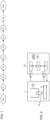
- Fig. 1 shows the method for controlling an optical system of a laser cutting machine L in a preferred embodiment.
- reference data can be generated. This can be done by carrying out a reference cutting process on the laser cutting machine L.
- first optical signals in particular a series of different images, are recorded, which represent a process light during a reference cutting process in a first state of the optical system, in particular in a cold state of the optical system or at the start of cutting.
- the reference data is generated from these first optical signals (image data).
- the reference data can match the first optical signals.
- at least one first feature vector is extracted from the first optical signals, which serves as reference data.
- a data structure namely the first data structure, can be created from the reference data by assigning a set focus position and a setting value of the optical system (e.g. position value of an optical lens) to the first optical signals, which were used to capture the first optical signals.
- already generated reference data can also be read in step S2.
- the reference data can be in an already generated form and, for example, stored in a memory from which it can be read out. Alternatively or cumulatively, it is possible to read out the first data structure.
- the optical system can be set to a target focus position.
- the target focus position defines the desired focus position with which the subsequent productive cutting process is to be carried out.
- the cutting process can be initiated or triggered in step S4. This can be done, for example, by means of a corresponding command.
- second optical signals in particular a series of different images, are read in in step S5 continuously or at certain times or after certain events.
- the read-in second optical signals are evaluated.
- a drift estimator 104 which can be provided as an electronic component.
- the drift estimator 104 is designed in particular to evaluate the read-in second optical signals by comparing them, in particular in preprocessed form (e.g. in the form of a second feature vector calculated from the second optical signals), with the reference data generated in step S1 or read in step S2 (with the first feature vector) in order to estimate a change in the focus position.
- preprocessed form e.g. in the form of a second feature vector calculated from the second optical signals
- an indirect image comparison algorithm can be used for feature comparison.
- the respective entries can be read out from the first and/or second data structure in order to estimate a drift based on the detected optical signals and to determine a corresponding control variable, in the simplest case an offset for the readjustment of the optical system, in particular the lens.
- step S7 at least one control variable for controlling or re-adjusting the optical system is determined based on the estimated change in the focus position in order to return the changed focus position to the respectively set DESIRED focus position.
- the method can then end or be applied continuously during the productive cutting process.
- the determined at least one controlled variable can be transmitted in step S8 to the control of the laser cutting machine L for application.
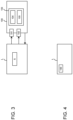
- Fig. 2 shows a schematic representation of a device 100 which is designed to carry out the method just described.
- the device 100 can be provided in different variants, which are described below in the Fig. 3 and Fig. 4 described in more detail In the Fig. 2
- the device 100 is designed with two reading interfaces 101, 102, which serve to read the first and second optical signals that are detected by one or more optical sensors of an optical sensor arrangement S, which can be arranged on the laser cutting machine L, in particular on the cutting head SK.
- the result that is provided after execution of the device 100, namely the determined at least one control variable, can be fed back to the laser cutting machine L or its control in the form of a control loop in order to regulate the laser cutting process accordingly, in particular in such a way that the current focus position, which may have been changed by heating, is returned to the DESIRED focus position.
- Fig. 2 (and Fig. 3 ) is marked with the arrow which is directed from the device 100 to the laser cutting machine L for transmitting the at least one controlled variable.
- the device further comprises a processor 103, the drift estimator 104 and the controller 105.
- the processor 103 is designed to set the optical system to a target focus position and to initiate a cutting process, which can also be referred to as a productive cutting process.
- the controller 105 is designed to determine at least one control variable for re-adjusting or regulating the optical system based on the change in the focus position estimated by the drift estimator 104 in order to return the changed focus position to the respectively set target focus position if the drift estimator 104 has estimated a change in the focus position that exceeds a predetermined threshold value.
- the drift estimator 104 can in particular, as explained above, be designed to compare a first feature vector (from the reference data) with a second feature vector from the current cutting process data.
- the device 100 can have a memory MEM for storing the read-in data, in particular the first and second optical signals, the set focus position from the reference cutting process, the DESIRED focus position from the (productive) cutting process and/or the estimated change in the focus position and/or the determined controlled variable.
- drift estimator 104 and the controller 105 can be formed in the processor 103, as shown in Fig. 3 is shown.
- Fig. 4 shown that the device 100 is implemented directly on the laser cutting machine.
- Fig. 5 is an overview figure showing the integration of the device 100 according to the invention for controlling the focus position in order to avoid drift due to thermal influences in advance.
- the drift estimator 104 estimates the actual or current focus position - possibly changed compared to the set DESIRED focus position.
- the read-in second optical signals can therefore be subjected to preprocessing, in particular to extract or calculate a second feature vector.
- the controller 105 determines the controlled variable in order to readjust or regulate the optical system and in particular its individual components via at least one actuator, so that the current focus position can be returned to the DESIRED focus position.
- the drift estimator 104 executes a preferably computer-implemented drift estimation method.
- the drift estimator 104 can execute a processing algorithm, in particular an indirect image comparison algorithm, in order to determine a controlled variable by comparing feature vectors calculated from the first and second optical signals and/or referencing to associated focus positions and/or setting values, which is fed to a controller 105 in order to return the possibly changed focus position to the DESIRED focus position that was set in step S3.
- a processing algorithm in particular an indirect image comparison algorithm
- the calculated features from the first optical signals (from the reference cutting process) or the first feature vector can be compared with the features from the second optical signals from the current cutting process or the second feature vector in order to then determine in the first data structure the associated further data sections that at least include the respective set focus position and can optionally also include the setting values for the actuators for adjusting the components of the optical system.
- the drift estimator 104 can use a thermal model to determine the controlled variable.
- the controlled variable can then be used to control at least one actuator such that the possibly changed focus position is returned to the DESIRED focus position that was set in step S3.
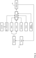
- optical system summarizes several components with different thermal cooling: A possible topology is shown in Fig. 6 Each component has its own thermal properties - some of them are cooled. All of them have an effect on the focus position. Therefore, according to the invention, several control variables are determined in order to be able to readjust or regulate the individual components of the optical system separately and/or individually.
- the components may include a fiber with an endcap lens, a mirror, one or more optical lenses, protective glasses, a telescope and a housing for the optical system.
- the drift estimator 104 estimates the current focus position and a deviation from the DESIRED focus position. If a deviation has been determined, the controller 105 determines a controlled variable in order to regulate the actuators accordingly in such a way that the current focus position can be transferred back to the DESIRED focus position that was set in step S3.
- a controller e.g. a programmable logic controller (PLC) calculates the paths for the next milliseconds.
- PLC programmable logic controller
- the feedback from the cutting process could only be read out using a light sensor that measures the process emission.
- it is possible to also regulate the cutting process i.e. in particular to readjust the components of the optical system based on the results of the drift estimator 104. This enables dynamic interaction.
- a modular frame is provided as an extension of the laser cutting machine L, which is connected to the PLC, the cutting head SK with the optical sensor of the optical sensor arrangement S (e.g. camera) and the user interface HMI (HMI in Fig. 2 shown).
- the HMI can be displayed in a browser and/or in a machine operating software.
- the recorded optical signals (camera images) and/or status information can be displayed in the HMI of the controller, e.g. of the device 100.
- Status information can be output, e.g.
- the data exchange between the components of the system can be carried out via a suitable network connection, such as: EtherCAT, Ethernet (ADS, http, GigE Vision).
- EtherCAT Ethernet
- ADS http, GigE Vision
- the system acts as a process controller and has several interfaces to devices or equipment on the laser cutting machine L. It collects or records sensor data such as first and second optical sensor data (photodiode for measuring the process light), nozzle distance signal, position of sensors on the axis and/or many other signals.
- sensor data such as first and second optical sensor data (photodiode for measuring the process light), nozzle distance signal, position of sensors on the axis and/or many other signals.
- the camera images (first and second optical signals) and optionally other machine data such as the cutting parameters are available.
- the system processes the data in real time.
- the image processor (implementable as part of the processor 103) extracts features using image algorithms and/or artificial intelligence methods, Cl.
- the system can execute a script to process the raw data (in particular the first and second optical signals) and/or the features extracted by the image processor using filters and conditions (if ... then ... else ... end).
- the script decides whether the cutting process and in particular the optical system should be adjusted and sets the offset/override values for re-adjustment (FeedOverride, LaserpowerOffset, FocalOffsetOptotune, FocalOffset, GasPressureOffset, NozzleDistanceOffset).
- the behavior of the L laser cutting machine can be quickly adjusted by changing the offsets/overrides.
- the system collects the first and second optical signals (images) or reads them in, and on the other hand, a return channel is also provided, in particular a fast Feedback channel to the control system, e.g. PLC, to set the offsets/overrides (readjustment/regulation) and/or exchange messages such as alarm conditions such as 'cutting loss' or 'nozzle loss'.
- a fast Feedback channel to the control system, e.g. PLC, to set the offsets/overrides (readjustment/regulation) and/or exchange messages such as alarm conditions such as 'cutting loss' or 'nozzle loss'.
- data showing irregular behavior can be collected and/or stored in a memory MEM (see Fig. 2 ).
- the dumps are automatically sent to a cloud storage (not shown).
- the cloud storage can be accessible via a network connection and implemented as a server, for example.
- the system or the framework presented here has a highly expandable architecture.
- the process can be started by reading in the cutting plan with the cutting parameters.
- the operator instructs the laser cutting machine L to start cutting a new sheet.
- the laser process emits process light during the cutting process.
- Camera images are captured with the cutting head camera from the emitted process light as first and second optical signals.
- a common preprocessor can be designed that rotates, crops, scales and normalizes the respective image. Gamma correction can also be used.
- the image processing is used to extract or calculate features 1..n, such as the mean value (image) or the diameter of the nozzle opening.
- the calculated features can be fed to further algorithms, in particular an indirect image comparison algorithm.
- the comparison between current data, in particular cutting data from the current cutting process, and reference cutting data from the reference cutting process takes place indirectly after the backbone with the features - either through the head or by applying a subtraction.
- the same images are processed in neural networks (convolutional neural networks).
- the models can predict in parallel so that several features A..Z are available.
- a multithreading implementation allows the simultaneous prediction of the same preprocessed image by different inference execution units operating in parallel. These execution units, which are applied in the inference phase, can be implemented in the device 100 and in particular in the processor 103.
- the process controller can act as a high-level arbiter (decision logic) to define useful loopback parameters, in particular the at least one controlled variable.
- the signals from time series can be filtered to have more confidence in the process state before a feedback parameter is set. If the process controller detects an ambiguous irregular pattern, the data is dumped in the dump controller (e.g. implemented on the memory MEM).
- the dumps can be uploaded to a cloud, either by ingestion (push operation, i.e. an automatic upload) or by manual upload. If possible, the labels are also included as a dump for storage and/or transmission, so that the neural network can start supervised learning, and in particular without the need for expensive manual creation of labeled data as training data.
- data In the development phase, data must be collected. The results must be defined and validated to obtain a labeled dataset of initial optical signals (images from the reference process).
- the data must be converted to tensors, the input format for a neural network training machine (e.g. keras/tensorflow, pytorch). By adjusting the network topology and hyperparameters, the accuracy and sensitivity of the model can be improved.
- the model must be saved in a compatible format so that the edge device of the laser cutting machine L can process the images in real time. Once the model is running on the machine L or a controller, the process controller will process the features in real time to improve the cutting process.
- new data is collected by compiling dumps.
- the data is uploaded to the data backbone either manually or automatically.
- the mix of new and old data is prepared to train and validate the neural network.
- model validation the model is deployed on laser cutting machines L.
- a mixed model input (input to the neural network) can be used.
- the preprocessed image is fed to the input of the model.
- scalars such as laser power, focus position, magnification, nozzle distance, gas pressure, speed, nozzle type and/or other cutting parameters can be sent to the model.
- the network receives multiple sensor values or images (history aggregation).
- a reference was taken for 0 drift.
- the topology may look like this: If features from the reference (reference cutting process) and the current process are available, a head (also a neural network) compares the two feature vectors and creates a new feature based on the comparison between the reference and the current process.
- the system with the drift estimator 104 can be described with reference to Fig. 7 be described as follows.
- Preprocessing The following functions can be applied to the first and/or second optical signals (camera image): rotation, scaling, cropping of the ROI (region of interest), gamma correction and/or normalization.
- the neural network e.g. Mobilenet_V2 as the backbone extracts/encodes the 576 features from 3 images.
- Mobilenet_V2 is a deep and highly optimized neural network that has been pre-trained.
- the decoder reproduces a synthetic image from the features. Comparing the real input and the generated output image, the reconstruction error (mean square error, mse) is low if the type of image was captured in the training set. If mse is high, new data needs to be collected.
- mse mean square error
- the first and second optical signals are, for example, Fig. 7 displayed, preprocessed and converted into first and second features (or first and second feature vectors).
- a feature vector vector with features is created using the backbone in the form of a KNN such as the Mobilenet, preferably from 3 images.
- 3 features are preferably created from 3x3 images.
- the 3 features from the first optical signals are preferably calculated only once and then written into a memory for later use.
- Process control After filtering, for example, the lens and/or mirror are checked (or the thermal model is refined in case of a shift).
- the process control can include the thermal model, which counteracts the expected drift during cutting using coefficient c_i.
- the drift is thus minimized with a constant optical system. However, if something changes in the optical system, drift could still occur.
- the process control continuously compares the results dfl_mean with an upper and lower threshold value (e.g. +/-0.3mm). If a drift is detected despite the thermal model, the process control adjusts the coefficients c_i. An adjustment could, for example, mean an increase in the coefficients c_i by 5%. The control or the closed loop takes place in such a way that the adjusted coefficients of the thermal model leads to a changed control of the optical actuators and thus to a reduction of the drift.
- an upper and lower threshold value e.g. +/-0.3mm
- the process control forces the change of the focus position (actuator for lenses and/or mirrors) in a sequence of, for example, 6 steps: [0, 0.166, 0.33, 0, -0.166, -0.33] (mm).
- the focus position actuator for lenses and/or mirrors
- mm a sequence of, for example, 6 steps: [0, 0.166, 0.33, 0, -0.166, -0.33] (mm).
- the cutting parameter can also be part of the data set.
- DoE design of experiment
- images from different steps are combined as pairs of first optical signals and second optical signals so that the head and the backbone can be trained/fine-tuned.
- the method or system presented here can be used for quality control through process stabilization. Furthermore, cutting losses and/or loss of cut are avoided through process stabilization.
Landscapes
- Engineering & Computer Science (AREA)
- Physics & Mathematics (AREA)
- Optics & Photonics (AREA)
- Mechanical Engineering (AREA)
- Plasma & Fusion (AREA)
- Artificial Intelligence (AREA)
- Evolutionary Computation (AREA)
- Laser Beam Processing (AREA)
Priority Applications (4)
| Application Number | Priority Date | Filing Date | Title |
|---|---|---|---|
| EP23186329.1A EP4494801A1 (fr) | 2023-07-19 | 2023-07-19 | Commande d'un système optique d'une machine de découpe au laser pour compenser la dérive thermique |
| PCT/EP2024/070291 WO2025017079A1 (fr) | 2023-07-19 | 2024-07-17 | Commande en boucle fermée d'un système optique d'une machine de découpe laser afin de compenser une dérive thermique |
| CN202480047669.8A CN121712609A (zh) | 2023-07-19 | 2024-07-17 | 对激光切割机的光学系统的闭环控制以补偿热漂移 |
| EP24745937.3A EP4680426A1 (fr) | 2023-07-19 | 2024-07-17 | Commande en boucle fermée d'un système optique d'une machine de découpe laser afin de compenser une dérive thermique |
Applications Claiming Priority (1)
| Application Number | Priority Date | Filing Date | Title |
|---|---|---|---|
| EP23186329.1A EP4494801A1 (fr) | 2023-07-19 | 2023-07-19 | Commande d'un système optique d'une machine de découpe au laser pour compenser la dérive thermique |
Publications (1)
| Publication Number | Publication Date |
|---|---|
| EP4494801A1 true EP4494801A1 (fr) | 2025-01-22 |
Family
ID=87419260
Family Applications (2)
| Application Number | Title | Priority Date | Filing Date |
|---|---|---|---|
| EP23186329.1A Withdrawn EP4494801A1 (fr) | 2023-07-19 | 2023-07-19 | Commande d'un système optique d'une machine de découpe au laser pour compenser la dérive thermique |
| EP24745937.3A Pending EP4680426A1 (fr) | 2023-07-19 | 2024-07-17 | Commande en boucle fermée d'un système optique d'une machine de découpe laser afin de compenser une dérive thermique |
Family Applications After (1)
| Application Number | Title | Priority Date | Filing Date |
|---|---|---|---|
| EP24745937.3A Pending EP4680426A1 (fr) | 2023-07-19 | 2024-07-17 | Commande en boucle fermée d'un système optique d'une machine de découpe laser afin de compenser une dérive thermique |
Country Status (3)
| Country | Link |
|---|---|
| EP (2) | EP4494801A1 (fr) |
| CN (1) | CN121712609A (fr) |
| WO (1) | WO2025017079A1 (fr) |
Cited By (1)
| Publication number | Priority date | Publication date | Assignee | Title |
|---|---|---|---|---|
| CN120395201A (zh) * | 2025-07-01 | 2025-08-01 | 苏州迪森科电子科技有限公司 | 一种光学元件激光切割的工艺控制方法及系统 |
Citations (6)
| Publication number | Priority date | Publication date | Assignee | Title |
|---|---|---|---|---|
| WO2011009594A1 (fr) * | 2009-07-20 | 2011-01-27 | Precitec Kg | Tête d'usinage au laser et procédé permettant de compenser la variation de position du foyer pour une tête d'usinage au laser |
| DE102012001609B3 (de) | 2012-01-26 | 2013-02-21 | Precitec Kg | Laserbearbeitungskopf |
| DE102018121836A1 (de) * | 2017-09-14 | 2019-03-14 | Fanuc Corporation | Laserbearbeitungsvorrichtung, die während der Laserbearbeitung eine Brennpunktverschiebung je nach dem Verschmutzungsgrad des Optischen Systems reguliert |
| WO2020069866A1 (fr) * | 2018-10-05 | 2020-04-09 | Precitec Gmbh & Co. Kg | Dispositif pour régler l'emplacement d'un point focal d'un faisceau laser dans un système de traitement au laser, système de traitement au laser le comprenant et procédé pour régler l'emplacement d'un point focal d'un faisceau laser dans un système de traitement au laser |
| DE102018119900B4 (de) | 2017-08-23 | 2020-12-10 | Fanuc Corporation | Laserbearbeitungsverfahren, das vor einer Laserbearbeitung eine Brennpunktverschiebung je nach der Art und des Grads der Verschmutzung eines externen optischen Systems reguliert |
| DE102019122064A1 (de) | 2019-08-16 | 2021-02-18 | Bystronic Laser Ag | Bearbeitungsvorrichtung zur Laserbearbeitung eines Werkstücks, Teilesatz für eine Bearbeitungsvorrichtung zur Laserbearbeitung eines Werkstücks und Verfahren zur Laserbearbeitung eines Werkstücks |
-
2023
- 2023-07-19 EP EP23186329.1A patent/EP4494801A1/fr not_active Withdrawn
-
2024
- 2024-07-17 CN CN202480047669.8A patent/CN121712609A/zh active Pending
- 2024-07-17 WO PCT/EP2024/070291 patent/WO2025017079A1/fr active Pending
- 2024-07-17 EP EP24745937.3A patent/EP4680426A1/fr active Pending
Patent Citations (6)
| Publication number | Priority date | Publication date | Assignee | Title |
|---|---|---|---|---|
| WO2011009594A1 (fr) * | 2009-07-20 | 2011-01-27 | Precitec Kg | Tête d'usinage au laser et procédé permettant de compenser la variation de position du foyer pour une tête d'usinage au laser |
| DE102012001609B3 (de) | 2012-01-26 | 2013-02-21 | Precitec Kg | Laserbearbeitungskopf |
| DE102018119900B4 (de) | 2017-08-23 | 2020-12-10 | Fanuc Corporation | Laserbearbeitungsverfahren, das vor einer Laserbearbeitung eine Brennpunktverschiebung je nach der Art und des Grads der Verschmutzung eines externen optischen Systems reguliert |
| DE102018121836A1 (de) * | 2017-09-14 | 2019-03-14 | Fanuc Corporation | Laserbearbeitungsvorrichtung, die während der Laserbearbeitung eine Brennpunktverschiebung je nach dem Verschmutzungsgrad des Optischen Systems reguliert |
| WO2020069866A1 (fr) * | 2018-10-05 | 2020-04-09 | Precitec Gmbh & Co. Kg | Dispositif pour régler l'emplacement d'un point focal d'un faisceau laser dans un système de traitement au laser, système de traitement au laser le comprenant et procédé pour régler l'emplacement d'un point focal d'un faisceau laser dans un système de traitement au laser |
| DE102019122064A1 (de) | 2019-08-16 | 2021-02-18 | Bystronic Laser Ag | Bearbeitungsvorrichtung zur Laserbearbeitung eines Werkstücks, Teilesatz für eine Bearbeitungsvorrichtung zur Laserbearbeitung eines Werkstücks und Verfahren zur Laserbearbeitung eines Werkstücks |
Non-Patent Citations (1)
| Title |
|---|
| VASILESKA EMA ET AL: "In-line monitoring of focus shift by kerf width detection with coaxial thermal imaging during laser cutting", THE INTERNATIONAL JOURNAL OF ADVANCED MANUFACTURING TECHNOLOGY, SPRINGER, LONDON, vol. 118, no. 7-8, 1 October 2021 (2021-10-01), pages 2587 - 2600, XP037665674, ISSN: 0268-3768, [retrieved on 20211001], DOI: 10.1007/S00170-021-07893-8 * |
Cited By (1)
| Publication number | Priority date | Publication date | Assignee | Title |
|---|---|---|---|---|
| CN120395201A (zh) * | 2025-07-01 | 2025-08-01 | 苏州迪森科电子科技有限公司 | 一种光学元件激光切割的工艺控制方法及系统 |
Also Published As
| Publication number | Publication date |
|---|---|
| WO2025017079A1 (fr) | 2025-01-23 |
| EP4680426A1 (fr) | 2026-01-21 |
| CN121712609A (zh) | 2026-03-20 |
Similar Documents
| Publication | Publication Date | Title |
|---|---|---|
| EP2456592B1 (fr) | Tête d'usinage au laser et procédé permettant de compenser la variation de position du foyer pour une tête d'usinage au laser | |
| DE4139414C2 (de) | Automatische Fokussierungseinrichtung | |
| EP3891561B1 (fr) | Dispositif de commande pour la commande d'une installation de production ainsi qu'installation de production et procédé | |
| EP2365890B1 (fr) | Procédé et dispositif de surveillance d'un processus d'usinage au laser exécuté sur une pièce, ainsi que tête d'usinage au laser équipée d'un tel dispositif | |
| EP2883647B1 (fr) | Procédé de configuration d'un dispositif d'usinage au laser | |
| EP0897786B1 (fr) | Procédé de régulation d'une machine de moulage par injection de matières plastiques | |
| DE69117851T2 (de) | Methode und Vorrichtung zur Regelung einer Formmaschine | |
| DE102013203338A1 (de) | Modellbasierte Steuerung einer optischen Abbildungseinrichtung | |
| EP3984688A1 (fr) | Méthode, programme ordinateur et système de coupage par laser pour coupage intelligent dans un angle | |
| EP4494801A1 (fr) | Commande d'un système optique d'une machine de découpe au laser pour compenser la dérive thermique | |
| DE102015009247A1 (de) | Numerische Steuerung mit Glätter zum Glätten von Geschwindigkeitsschwankungen aufgrund abrupter Änderungen von Postitionsabweichungen | |
| EP3034984B1 (fr) | Procede et dispositif de stabilisation locale d'une tache de rayonnement sur un objet cible eloigne | |
| EP3233416B1 (fr) | Procédé et dispositif de mesure pour surveiller l'extensibilité lors de la fabrication d'un film étirable dans un procédé de feuille mince moulée | |
| EP2288969B1 (fr) | Système de conduite d'une installation avec optimisation du modèle en plusieurs phases | |
| DE102020100345B4 (de) | System und Verfahren zum Überwachen eines Laserbearbeitungsprozesses sowie dazugehöriges Laserbearbeitungssystem | |
| EP1001320B1 (fr) | Procédé pour l' identification d' un processus avec retard utilisant une compensation et dispositif pour la commande d' un tel processus | |
| EP4275099B1 (fr) | Procédé et systèmes de détermination des paramètres de compensation | |
| DE102022101429A1 (de) | Strahlschneidverfahren, Computerprogramm und Strahlschneidanlage | |
| WO2022189050A1 (fr) | Production de caméras avec un taux de rejet réduit | |
| DE102023131262A1 (de) | Anpassungsvorrichtung, spritzgiessmaschine und programm | |
| DE102011075723A1 (de) | Verfahren zur Regelung eines Spritzgießprozesses | |
| EP4495720A1 (fr) | Procédé et dispositif d'optimisation d'un loc-watchdog (perte de coupe-watchog) pour une machine de découpe au laser | |
| DE102008038359A1 (de) | Mikroskop und Mikroskopierverfahren | |
| EP2821215B1 (fr) | Procédé de déformation présentant un réglage d'une caractéristique géométrique d'une pièce à usiner et dispositif associé | |
| DE102022104082A1 (de) | Linienoptiksystem |
Legal Events
| Date | Code | Title | Description |
|---|---|---|---|
| PUAI | Public reference made under article 153(3) epc to a published international application that has entered the european phase |
Free format text: ORIGINAL CODE: 0009012 |
|
| STAA | Information on the status of an ep patent application or granted ep patent |
Free format text: STATUS: THE APPLICATION HAS BEEN PUBLISHED |
|
| AK | Designated contracting states |
Kind code of ref document: A1 Designated state(s): AL AT BE BG CH CY CZ DE DK EE ES FI FR GB GR HR HU IE IS IT LI LT LU LV MC ME MK MT NL NO PL PT RO RS SE SI SK SM TR |
|
| STAA | Information on the status of an ep patent application or granted ep patent |
Free format text: STATUS: THE APPLICATION IS DEEMED TO BE WITHDRAWN |
|
| 18D | Application deemed to be withdrawn |
Effective date: 20250723 |