EP4494854A2 - Verbundartikel mit einem strukturierten porösen körper und einem schaum und verfahren zur herstellung eines strukturierten porösen körpers und eines partikelschaums - Google Patents
Verbundartikel mit einem strukturierten porösen körper und einem schaum und verfahren zur herstellung eines strukturierten porösen körpers und eines partikelschaums Download PDFInfo
- Publication number
- EP4494854A2 EP4494854A2 EP24210936.1A EP24210936A EP4494854A2 EP 4494854 A2 EP4494854 A2 EP 4494854A2 EP 24210936 A EP24210936 A EP 24210936A EP 4494854 A2 EP4494854 A2 EP 4494854A2
- Authority
- EP
- European Patent Office
- Prior art keywords
- mould
- efb
- foam beads
- expanded foam
- composite article
- Prior art date
- Legal status (The legal status is an assumption and is not a legal conclusion. Google has not performed a legal analysis and makes no representation as to the accuracy of the status listed.)
- Withdrawn
Links
Images

Classifications
-
- B—PERFORMING OPERATIONS; TRANSPORTING
- B29—WORKING OF PLASTICS; WORKING OF SUBSTANCES IN A PLASTIC STATE IN GENERAL
- B29C—SHAPING OR JOINING OF PLASTICS; SHAPING OF MATERIAL IN A PLASTIC STATE, NOT OTHERWISE PROVIDED FOR; AFTER-TREATMENT OF THE SHAPED PRODUCTS, e.g. REPAIRING
- B29C44/00—Shaping by internal pressure generated in the material, e.g. swelling or foaming ; Producing porous or cellular expanded plastics articles
- B29C44/02—Shaping by internal pressure generated in the material, e.g. swelling or foaming ; Producing porous or cellular expanded plastics articles for articles of definite length, i.e. discrete articles
- B29C44/12—Incorporating or moulding on preformed parts, e.g. inserts or reinforcements
-
- B—PERFORMING OPERATIONS; TRANSPORTING
- B29—WORKING OF PLASTICS; WORKING OF SUBSTANCES IN A PLASTIC STATE IN GENERAL
- B29C—SHAPING OR JOINING OF PLASTICS; SHAPING OF MATERIAL IN A PLASTIC STATE, NOT OTHERWISE PROVIDED FOR; AFTER-TREATMENT OF THE SHAPED PRODUCTS, e.g. REPAIRING
- B29C44/00—Shaping by internal pressure generated in the material, e.g. swelling or foaming ; Producing porous or cellular expanded plastics articles
- B29C44/02—Shaping by internal pressure generated in the material, e.g. swelling or foaming ; Producing porous or cellular expanded plastics articles for articles of definite length, i.e. discrete articles
- B29C44/04—Shaping by internal pressure generated in the material, e.g. swelling or foaming ; Producing porous or cellular expanded plastics articles for articles of definite length, i.e. discrete articles consisting of at least two parts of chemically or physically different materials, e.g. having different densities
-
- B—PERFORMING OPERATIONS; TRANSPORTING
- B29—WORKING OF PLASTICS; WORKING OF SUBSTANCES IN A PLASTIC STATE IN GENERAL
- B29C—SHAPING OR JOINING OF PLASTICS; SHAPING OF MATERIAL IN A PLASTIC STATE, NOT OTHERWISE PROVIDED FOR; AFTER-TREATMENT OF THE SHAPED PRODUCTS, e.g. REPAIRING
- B29C44/00—Shaping by internal pressure generated in the material, e.g. swelling or foaming ; Producing porous or cellular expanded plastics articles
- B29C44/02—Shaping by internal pressure generated in the material, e.g. swelling or foaming ; Producing porous or cellular expanded plastics articles for articles of definite length, i.e. discrete articles
- B29C44/12—Incorporating or moulding on preformed parts, e.g. inserts or reinforcements
- B29C44/1285—Incorporating or moulding on preformed parts, e.g. inserts or reinforcements the preformed part being foamed
-
- B—PERFORMING OPERATIONS; TRANSPORTING
- B29—WORKING OF PLASTICS; WORKING OF SUBSTANCES IN A PLASTIC STATE IN GENERAL
- B29C—SHAPING OR JOINING OF PLASTICS; SHAPING OF MATERIAL IN A PLASTIC STATE, NOT OTHERWISE PROVIDED FOR; AFTER-TREATMENT OF THE SHAPED PRODUCTS, e.g. REPAIRING
- B29C44/00—Shaping by internal pressure generated in the material, e.g. swelling or foaming ; Producing porous or cellular expanded plastics articles
- B29C44/34—Auxiliary operations
- B29C44/3415—Heating or cooling
-
- B—PERFORMING OPERATIONS; TRANSPORTING
- B29—WORKING OF PLASTICS; WORKING OF SUBSTANCES IN A PLASTIC STATE IN GENERAL
- B29C—SHAPING OR JOINING OF PLASTICS; SHAPING OF MATERIAL IN A PLASTIC STATE, NOT OTHERWISE PROVIDED FOR; AFTER-TREATMENT OF THE SHAPED PRODUCTS, e.g. REPAIRING
- B29C44/00—Shaping by internal pressure generated in the material, e.g. swelling or foaming ; Producing porous or cellular expanded plastics articles
- B29C44/34—Auxiliary operations
- B29C44/3415—Heating or cooling
- B29C44/3426—Heating by introducing steam in the mould
-
- B—PERFORMING OPERATIONS; TRANSPORTING
- B29—WORKING OF PLASTICS; WORKING OF SUBSTANCES IN A PLASTIC STATE IN GENERAL
- B29C—SHAPING OR JOINING OF PLASTICS; SHAPING OF MATERIAL IN A PLASTIC STATE, NOT OTHERWISE PROVIDED FOR; AFTER-TREATMENT OF THE SHAPED PRODUCTS, e.g. REPAIRING
- B29C44/00—Shaping by internal pressure generated in the material, e.g. swelling or foaming ; Producing porous or cellular expanded plastics articles
- B29C44/34—Auxiliary operations
- B29C44/36—Feeding the material to be shaped
- B29C44/38—Feeding the material to be shaped into a closed space, i.e. to make articles of definite length
- B29C44/44—Feeding the material to be shaped into a closed space, i.e. to make articles of definite length in solid form
- B29C44/445—Feeding the material to be shaped into a closed space, i.e. to make articles of definite length in solid form in the form of expandable granules, particles or beads
-
- B—PERFORMING OPERATIONS; TRANSPORTING
- B29—WORKING OF PLASTICS; WORKING OF SUBSTANCES IN A PLASTIC STATE IN GENERAL
- B29C—SHAPING OR JOINING OF PLASTICS; SHAPING OF MATERIAL IN A PLASTIC STATE, NOT OTHERWISE PROVIDED FOR; AFTER-TREATMENT OF THE SHAPED PRODUCTS, e.g. REPAIRING
- B29C44/00—Shaping by internal pressure generated in the material, e.g. swelling or foaming ; Producing porous or cellular expanded plastics articles
- B29C44/34—Auxiliary operations
- B29C44/58—Moulds
-
- B—PERFORMING OPERATIONS; TRANSPORTING
- B29—WORKING OF PLASTICS; WORKING OF SUBSTANCES IN A PLASTIC STATE IN GENERAL
- B29C—SHAPING OR JOINING OF PLASTICS; SHAPING OF MATERIAL IN A PLASTIC STATE, NOT OTHERWISE PROVIDED FOR; AFTER-TREATMENT OF THE SHAPED PRODUCTS, e.g. REPAIRING
- B29C64/00—Additive manufacturing, i.e. manufacturing of three-dimensional [3D] objects by additive deposition, additive agglomeration or additive layering, e.g. by 3D printing, stereolithography or selective laser sintering
- B29C64/10—Processes of additive manufacturing
- B29C64/141—Processes of additive manufacturing using only solid materials
- B29C64/153—Processes of additive manufacturing using only solid materials using layers of powder being selectively joined, e.g. by selective laser sintering or melting
-
- B—PERFORMING OPERATIONS; TRANSPORTING
- B29—WORKING OF PLASTICS; WORKING OF SUBSTANCES IN A PLASTIC STATE IN GENERAL
- B29C—SHAPING OR JOINING OF PLASTICS; SHAPING OF MATERIAL IN A PLASTIC STATE, NOT OTHERWISE PROVIDED FOR; AFTER-TREATMENT OF THE SHAPED PRODUCTS, e.g. REPAIRING
- B29C67/00—Shaping techniques not covered by groups B29C39/00 - B29C65/00, B29C70/00 or B29C73/00
- B29C67/20—Shaping techniques not covered by groups B29C39/00 - B29C65/00, B29C70/00 or B29C73/00 for porous or cellular articles, e.g. of foam plastics, coarse-pored
- B29C67/205—Shaping techniques not covered by groups B29C39/00 - B29C65/00, B29C70/00 or B29C73/00 for porous or cellular articles, e.g. of foam plastics, coarse-pored comprising surface fusion, and bonding of particles to form voids, e.g. sintering
-
- B—PERFORMING OPERATIONS; TRANSPORTING
- B32—LAYERED PRODUCTS
- B32B—LAYERED PRODUCTS, i.e. PRODUCTS BUILT-UP OF STRATA OF FLAT OR NON-FLAT, e.g. CELLULAR OR HONEYCOMB, FORM
- B32B5/00—Layered products characterised by the non- homogeneity or physical structure, i.e. comprising a fibrous, filamentary, particulate or foam layer; Layered products characterised by having a layer differing constitutionally or physically in different parts
- B32B5/18—Layered products characterised by the non- homogeneity or physical structure, i.e. comprising a fibrous, filamentary, particulate or foam layer; Layered products characterised by having a layer differing constitutionally or physically in different parts characterised by features of a layer of foamed material
-
- B—PERFORMING OPERATIONS; TRANSPORTING
- B32—LAYERED PRODUCTS
- B32B—LAYERED PRODUCTS, i.e. PRODUCTS BUILT-UP OF STRATA OF FLAT OR NON-FLAT, e.g. CELLULAR OR HONEYCOMB, FORM
- B32B5/00—Layered products characterised by the non- homogeneity or physical structure, i.e. comprising a fibrous, filamentary, particulate or foam layer; Layered products characterised by having a layer differing constitutionally or physically in different parts
- B32B5/22—Layered products characterised by the non- homogeneity or physical structure, i.e. comprising a fibrous, filamentary, particulate or foam layer; Layered products characterised by having a layer differing constitutionally or physically in different parts characterised by the presence of two or more layers which are next to each other and are fibrous, filamentary, formed of particles or foamed
- B32B5/32—Layered products characterised by the non- homogeneity or physical structure, i.e. comprising a fibrous, filamentary, particulate or foam layer; Layered products characterised by having a layer differing constitutionally or physically in different parts characterised by the presence of two or more layers which are next to each other and are fibrous, filamentary, formed of particles or foamed at least two layers being foamed and next to each other
-
- B—PERFORMING OPERATIONS; TRANSPORTING
- B33—ADDITIVE MANUFACTURING TECHNOLOGY
- B33Y—ADDITIVE MANUFACTURING, i.e. MANUFACTURING OF THREE-DIMENSIONAL [3D] OBJECTS BY ADDITIVE DEPOSITION, ADDITIVE AGGLOMERATION OR ADDITIVE LAYERING, e.g. BY 3D PRINTING, STEREOLITHOGRAPHY OR SELECTIVE LASER SINTERING
- B33Y10/00—Processes of additive manufacturing
-
- B—PERFORMING OPERATIONS; TRANSPORTING
- B33—ADDITIVE MANUFACTURING TECHNOLOGY
- B33Y—ADDITIVE MANUFACTURING, i.e. MANUFACTURING OF THREE-DIMENSIONAL [3D] OBJECTS BY ADDITIVE DEPOSITION, ADDITIVE AGGLOMERATION OR ADDITIVE LAYERING, e.g. BY 3D PRINTING, STEREOLITHOGRAPHY OR SELECTIVE LASER SINTERING
- B33Y80/00—Products made by additive manufacturing
-
- B—PERFORMING OPERATIONS; TRANSPORTING
- B29—WORKING OF PLASTICS; WORKING OF SUBSTANCES IN A PLASTIC STATE IN GENERAL
- B29K—INDEXING SCHEME ASSOCIATED WITH SUBCLASSES B29B, B29C OR B29D, RELATING TO MOULDING MATERIALS OR TO MATERIALS FOR MOULDS, REINFORCEMENTS, FILLERS OR PREFORMED PARTS, e.g. INSERTS
- B29K2105/00—Condition, form or state of moulded material or of the material to be shaped
- B29K2105/04—Condition, form or state of moulded material or of the material to be shaped cellular or porous
-
- B—PERFORMING OPERATIONS; TRANSPORTING
- B29—WORKING OF PLASTICS; WORKING OF SUBSTANCES IN A PLASTIC STATE IN GENERAL
- B29K—INDEXING SCHEME ASSOCIATED WITH SUBCLASSES B29B, B29C OR B29D, RELATING TO MOULDING MATERIALS OR TO MATERIALS FOR MOULDS, REINFORCEMENTS, FILLERS OR PREFORMED PARTS, e.g. INSERTS
- B29K2105/00—Condition, form or state of moulded material or of the material to be shaped
- B29K2105/25—Solid
- B29K2105/251—Particles, powder or granules
Definitions
- the present invention relates to a process for the production of a composite article comprising a structured porous body (PB) and a particle foam (PF), wherein the provided structured porous body (PB) is inserted into a mould (M) and the mould (M) is filled with expanded foam beads (EFB) so that the expanded foam beads (EFB) are in contact with each other and the structured porous body (PB) is at least partially in contact with the expanded foam beads (EFB). Then, the expanded foam beads (EFB) are thermally welded, wherein the particle foam (PF) is built and the composite article is obtained.
- the present invention relates to a composite article obtained by this process, as well as to a composite article comprising a structured porous body (PB) and a particle foam (PF).
- the present invention further relates to the use of the inventive composite articles in the shoe industry, in the sports and leisure sector, in vehicle construction, in the medical sector, in mechanical engineering and in the logistics sector. Furthermore, the present invention relates to a composite article comprising a structured porous body (PB) and a foam (F), wherein the structured porous body (PB) and the foam (F) comprise the same polymer (P).
- PB structured porous body
- F foam
- Structured porous bodies like, for example, triply periodic minimal surfaces (TPMS) or lattices generally comprise a three-dimensional network of node points, connected to one another by struts, and a void volume present between the struts.
- TPMS triply periodic minimal surfaces
- the porous bodies are periodically structured, they commonly comprise a unit cell that repeats in at least two dimensions.
- a 3D-printing technology is often used. Similar to foams the properties can be controlled by the density of the structured porous bodies.
- the mechanical properties can be controlled by the unit cell type, size and/or the beam diameter of the 3D-printer.
- structured porous bodies are a buckling under a certain pressure which means that, at a certain pressure, some of the struts of the structured porous bodies buckle and the resistance against compression rapidly drops.
- structured porous bodies are open structures, they can easily take up dirt and water if not sealed. Because of the large surface area of the structured porous bodies, they are also more quickly affected by environmental conditions like moisture and UV radiation. In addition, they often need expensive post-processing to clean them from residue powder and to smoothen the surface, especially when they are produced by a powder-or filament-based technology.
- Another disadvantage is that, due to the high complexity of 3D-printed (periodically) structured porous bodies, it is difficult to obtain a high part-to-part consistency, as small variations in the printing process can have a significant effect on the final part behavior.
- EP 3 292 795 A1 describes the use of an elastic polymer for the production of a porous body in an additive manufacturing process.
- the polymer is selected, for example, from thermoset polyurethane elastomers (PUR) or thermoplastic urethane-based elastomers (TPU).
- PUR thermoset polyurethane elastomers
- TPU thermoplastic urethane-based elastomers
- the porous body can target a 40% compression of ⁇ 10 to ⁇ 100 kPa.
- CN 109688877 A also describes a porous body produced in an additive manufacturing method.
- the material of the body is in a first region of the body different from the material in a second region of the body.
- the materials are, for example, selected from thermoplastic elastomers (TPE), thermoplastic polyurethane (TPU) or polyacrylate.
- TPE thermoplastic elastomers
- TPU thermoplastic polyurethane
- the porous body also has a compression hardness (40% compression) in at least one spatial direction of ⁇ 10 to ⁇ 100 kPa.
- US 2019/0357695 A1 describes a composite article comprising a body and solid foam, wherein the material of the body is different from that of the foam.
- the body is produced by means of an additive manufacturing process and is at least partially formed from a polymeric material selected from the group of, for example, thermosetting polyurethanes, epoxides or urethane-based thermoplastic elastomers (TPU).
- TPU thermoplastic elastomers
- the composite article is produced by contacting the body with a reaction mixture which reacts to afford polymer foam, wherein the reaction mixture at least partially penetrates into the interior of the body.
- the reaction mixture may contain polyisocyanates, polyols and additionally chemical and/or physical blowing agents.
- the composite article features good weathering stability.
- the article " The formation and stabilization of lattice structures via foam addition” presents a composite comprising a low-density polymer lattice structure with centimetre-scale voids and a stochastic foam with pores in the sub-millimetre scale in the spaces between the lattice struts.
- the lattice is made of photo-cured thiol-ene and coated with polyurethane pre-polymers in a high-speed mixer to obtain the composite.
- US 2016/0324260 A1 describes an article of footwear with a midsole, wherein the midsole includes a lattice structure with a plurality of laths.
- the lattice structure is provided by a fused nylon or PTFE powder.
- the formation of the foam within the structured porous body can lead to several problems: For example, the exothermic formation of the foam can lead to high temperatures that destroy or deteriorate the structured porous body. Also, the strong and quick expansion of the foam can break some of the connections or struts of the structured porous body. Furthermore, the formation of the foam can also be influenced by the structured porous body, when the structured porous body, for example, acts as a nucleation site and leads to unexpected or uncontrollable foam structures. Finally, most examples in the state-of-the-art use different material chemistries for the structured porous body and the foam, which can lead to compatibility issues and also makes recycling much more difficult.
- the object underlying the present invention was, therefore, to provide an improved process for producing a composite article comprising a structured porous body and a foam, which also allows independently tuning the mechanical properties of the structured porous body and the foam comprised in the composite article. With this process it should also be possible to improve opposite mechanical properties of the structured porous body and the foam independently.
- a further object of the present invention was to provide a composite material having good recycling properties.
- the object is achieved by a process for the production of a composite article comprising a structured porous body (PB) and a particle foam (PF), wherein the process comprises the following steps a) to d)
- the object is achieved by composite article comprising a structured porous body (PB) and a foam (F), wherein the structured porous body (PB) and the foam (F) each comprise the same polymer (P).
- stiffness and compression hardness of the composite article could be increased compared to the stiffness of pure particle foam (PF) at lower density without influencing the rebound significantly. Due to the use of structured porous bodies (PB), it is also possible to achieve a stiffness gradient.
- PB structured porous bodies
- the composite article behaves stiffer in static and dynamic testing as a particle foam (PF) without structured porous body (PB) although the structured porous body (PB) is softer than the particle foam (PF).
- the structured porous body (PB) does not show any negative influence on the thermally welding of the expanded foam beads (EFB) and the rebound.
- PB structured porous body
- F foam
- Composite articles per se are in principle known to the person skilled in the art. They are usually composed of different solid-state components (materials) which normally differ from each other in their chemical nature and/or have special physical-mechanical properties due to their geometry.
- the "composite article” in the context of the present invention is preferably composed of a structured porous body (PB) and a particle foam (PF), wherein the particle foam (PF) is prepared by thermally welding expanded foam beads (EFB).
- PB structured porous body
- PF particle foam
- the composite article in general is produced by a process comprising the steps a) to d).
- step a the structured porous body (PB) is provided.
- the structured porous body (PB) preferably comprises at least one thermoplastic or thermoset polymer (TP) selected from the group consisting of impact modified vinyl-aromatic copolymers, thermoplastic styrene-based elastomers (S-TPE), polyolefins (PO), aliphatic-aromatic copolyesters, polycarbonates, thermoplastic polyurethanes (TPU), polyamides (PA), polyphenylene sulphides (PPS), polyaryletherketones (PAEK), polysulfones and polyimides (PI), more preferably of thermoplastic styrene-based elastomers (S-TPE), thermoplastic polyurethanes (TPU) and polyamides, and particularly preferably of thermoplastic polyurethanes (TPU).
- TP thermoplastic or thermoset polymer
- the structured porous body comprises preferably a three-dimensional network of node points and a void volume, wherein the node points are joined to another by struts and the void volume is present between the struts.
- the structured porous body (PB) can be periodically structured.
- the structured porous body (PB) comprises many identical unit cells and is defined by the design of a single unit cell which repeats itself in at least two dimensions.
- PB lattices or triply periodic minimal surfaces
- a "lattice” comprises a three-dimensional network of node points joined to one another by struts, and a void volume present between the struts, wherein one node point of the lattice can be connected with the same and/or a different quantity of struts as another node point of the lattice, and wherein the length of one strut of the lattice can be equal and/or different than another strut of the lattice. Therefore, in analogy to the terminology of crystallography, a lattice according to the invention can comprise a unit cell that repeats periodically in two or three dimensions and/or an amorphous structure.
- triply periodic minimal surface means that the minimal surface is comprised of a unit cell that repeats in three dimensions and has one of the two-hundred thirty crystallographic space groups as its symmetry group.
- the structured porous body (PB) is a lattice.
- the structured porous body (PB) is preferably produced by a three-dimensional (3D) printing process.
- 3D (three-dimensional) printing processes as such are known to a person skilled in the art.
- all known different 3D printing techniques such as selective laser melting, electron beam melting, selective laser sintering (SLS), the multi-jet fusion process (MJF), stereo lithography (SLA), digital light production (DLP), or the fused deposition modelling (FDM) process can be used.
- SLS selective laser melting
- MJF multi-jet fusion process
- SLA stereo lithography
- DLP digital light production
- FDM fused deposition modelling
- the 3D printing process is preferably a sintering process, more preferably a selective laser sintering process (SLS) or a multi-jet fusion process (MJF).
- SLS selective laser sintering process
- MTF multi-jet fusion process
- the provision of the structured porous body (PB) via a sintering process preferably comprises the following steps i) and ii):
- step ii) the layer of the sinter powder (SP) is usually lowered by the layer thickness of the layer of the sinter powder (SP) provided in step i) and a further layer of sinter powder (SP) is applied. This is then sintered again according to step ii).
- the upper layer of the sinter powder (SP) bonds with the lower layer of the sinter powder (SP)
- the particles of the sinter powder (SP) bond with each other within the upper layer by melting.
- steps i) and ii) can thus be repeated.
- the structured porous body (PB) By repeating the lowering of the powder bed, the application of the sinter powder (SP) and the sintering and thus the melting of the sinter powder (SP), the structured porous body (PB) is produced.
- An additional supporting material is not necessary because the non-melted sinter powder (SP) itself acts as supporting material.
- SLS selective laser sintering process
- MTF multi-jet fusion process
- the sinter powder (SP) usually has particles. These particles have, for example, a size (D50 value) in the range of 10 to 190 ⁇ m, preferably in the range of 15 to 150 ⁇ m, more preferably in the range of 20 to 110 ⁇ m and especially preferably in the range of 40 to 100 ⁇ m.
- D50 value a size in the range of 10 to 190 ⁇ m, preferably in the range of 15 to 150 ⁇ m, more preferably in the range of 20 to 110 ⁇ m and especially preferably in the range of 40 to 100 ⁇ m.
- D50 is understood to mean the particle size at which 50% by volume of the particles based on the total volume of the particles are smaller than or equal to D50 and 50% by volume of the particles based on the total volume of the particles are larger than D50.
- the sinter powder (SP) usually has a melting temperature (T M(SP) ) in the range from 80 to 220°C.
- T M(SP) melting temperature
- the melting temperature (T M(SP) ) of the sinter powder (SP) is in the range from 100 to 190°C and especially preferably in the range of 120 to 170°C.
- the melting temperature (T M(SP) ) is determined within the context of the present invention by means of differential scanning calorimetry (DSC). It is customary to measure a heating run (H) and a cooling run (K), each with a heating rate and cooling rate of 20 K/min respectively, wherein a DSC diagram is obtained. The melting temperature (T M(SP) ) is then understood to be the temperature at which the melting peak of the heating run (H) of the DSC diagram shows a maximum.
- step b) the structured porous body (PB) provided in step a) is inserted into a mould (M), wherein the mould (M) preferably comprises a fixed part (FP) and a moveable part (MP) and the structured porous body (PB) is preferably inserted either into the fixed part (FP) or into the moveable part (MP) of the mould (M).
- the mould (M) preferably comprises a fixed part (FP) and a moveable part (MP) and the structured porous body (PB) is preferably inserted either into the fixed part (FP) or into the moveable part (MP) of the mould (M).
- the structured porous body (PB) fits exactly into the mould (M), preferably into the fixed part (FP) or the moveable part (MP) of the mould (M); however it is likewise possible that the structured porous body (PB) fills only part of the mould (M), preferably the fixed part (FP) or the moveable part (MP) of the mould.
- the term "fits exactly” means that the length of the structured porous body (PB) corresponds to at least 95%, preferably to at least 98%, to the length of the mould (M), preferably to the length of the fixed part (FP) or the moveable part (MP) of the mould (M), that the width of the structured porous body (PB) corresponds to at least 95%, preferably to at least 98%, to the width of the mould (M), preferably to the width of the fixed part (FP) or the moveable part (MP) of the mould (M), and that the thickness of the structured porous body (PB) corresponds to at least 95%, preferably to at least 98%, to the thickness of the mould (M), preferably to the thickness of the fixed part (FP) or the moveable part (MP) of the mould (M).
- the term "fills only part of the mould (M)” means that the length of the structured porous body (PB) corresponds to less than 95% to the length of the mould (M), preferably to the length of the fixed part (FP) or the moveable part (MP) of the mould (M), that the width of the structured porous body (PB) corresponds to less than 95% to the width of the mould (M), preferably to the width of the fixed part (FP) or the moveable part (MP) of the mould (M), and that the thickness of the structured porous body (PB) corresponds to less than 95% to the thickness of the mould (M), preferably to the thickness of the fixed part (FP) or the moveable part (MP) of the mould (M).
- step c) the mould (M) is filled with expanded foam beads (EFB) so that the expanded foam beads (EFB) are in contact with each other and the structured porous body (PB) is at least partially in contact with the expanded foam beads (EFB).
- EFB expanded foam beads
- the term "at least partially in contact” means that at least 10%, preferably at least 20%, more preferably at least 30%, of the surface of the structured porous body (PB) are in contact with the expanded foam beads (EFB).
- Expanded foam beads (EFB) per se are in principle known to the person skilled in the art. Suitable expanded foam beads are, for example, disclosed in WO 94/20568 A1 , WO 2007/082838 A1 , WO 2017/030835 A1 , WO 2013/153190 A1 or WO 2010/010010 A1 .
- the expanded foam beads (EFB) preferably comprise a thermoplastic elastomer (TPE), polystyrene (EPS), ethylene vinyl acetate (EVA) or polyolefine. Mixtures of the expanded foam beads (EFB) comprising the polymers indicated above can also be used to fill the mould (M). More preferably, the expanded foam beads (EFB) comprise a thermoplastic elastomer (TPE).
- thermoplastic elastomers comprised in the expanded foam beads (EFB) are thermoplastic polyurethane, thermoplastic polyamide, thermoplastic polyether ester, thermoplastic (co)polyester, thermoplastic vulcanisate, thermoplastic polyolefine and thermoplastic styrene block copolymer.
- the expanded foam beads (EFB) comprise thermoplastic polyurethane.
- Especially preferred expanded foam beads (EFB) are the expanded foam beads comprising thermoplastic polyurethane, available under the trade name Infinergy ® from BASF SE.
- the expanded foam beads have preferably an average diameter of 0.2 to 20 mm, preferably of 0.5 to 15 mm and in particular of 1 to 12 mm.
- the average diameter means the average diameter of the longest dimension.
- the expanded foam beads (EFB) in the context of the present invention preferably have a melting point T M(EFB) ⁇ 300°C, more preferably ⁇ 250°C and in particular ⁇ 220°C, determined by means of differential scanning calorimetry (DSC) according to DIN EN ISO 11357-1:2016, whereas the melting point is determined from the DSC curve according to DIN EN ISO 11357-3:2018.
- DSC differential scanning calorimetry
- the expanded foam beads have closed cells.
- closed cells means that the cavities of the cells enclosed in the expanded foam beads (EFB) are not connected to each other by openings in the walls of the respective cells.
- a closed-cell material always comprises more closed cells than open cells (relative to the total number of cells).
- the expanded foam beads (EFB) having closed cells comprise at least 80%, more preferably at least 90%, most preferably at least 95%, of closed cells, based on the total number of cells in the expanded foam beads (EFB) having closed cells.
- the expanded foam beads (EFB) within the obtained composite article have a bulk density in the range from 20 to 350 kg/m 3 , preferably in the range from 60 to 210 kg/m 3 , and more preferably in the range from 100 to 170 kg/m 3 .
- step d the expanded foam beads (EFB) are thermally welded, wherein the particle foam (PF) is built and the composite article is obtained.
- the particle foam (PF) in the context of the present invention, is a foam in which the expanded foam beads (EFB) are bonded.
- the thermal welding can be carried out by steam, microwave, variotherm or radio frequency, preferably by steam.
- the term "by variotherm" means that the thermal welding is carried out under a forced dynamic temperature curve.
- the thermal welding in step d) is carried out by steaming the expanded foam beads (EFB) at a first temperature T 1 which is above the softening temperature T S of the expanded foam beads (EFB).
- the first temperature T 1 in step d) is preferably in the range from 90 to 200°C, more preferably in the range from 100 to 170°C, most preferably in the range from 110 to 140°C.
- step e2 is carried out, in which the mould (M) is partially closed by moving the moveable part (MP) of the mould (M) so that a crack (C) is built between the fixed part (FP) and the moveable part (MP), wherein the thickness of the crack (C) is preferably in the range from 5 to 24 mm.
- the steaming of the expanded foam beads (EFB) according to step d) preferably comprises the following steps d1) to d4)
- the term "the steam is subsequently supplied on the side of the moveable part (MP) and on the side of the fixed part (FP) and exits the mould (M) subsequently on the side of the fixed part (FP) and on the side of the moveable part (MP), respectively” according to step d1) means either that the steam is first supplied on the side of the fixed part (FP) of the mould (M) and exits the mould (M) on the side of the moveable part (MP) of the mould (M) and after that, the steam is supplied on the side of the moveable part (MP) of the mould (M) and exits the mould (M) on the side of the fixed part (FP) of the mould (M), or the steam is first supplied on the side of the moveable part (MP) of the mould (M) and exits the mould (M) on the side of the fixed part (FP) of the mould (M) and after that, the steam is supplied on the side of the fixed part (FP) of the mould (M) and exits the mould (M) according to step d1)
- the term "subsequently supplied on the side of the moveable part (MP) and on the side of the fixed part (FP)" according to step d3) means either that the steam is first supplied on the side of the fixed part (FP) of the mould (M) and after that, the steam is supplied on the side of the moveable part (MP) of the mould (M), or the steam is first supplied on the side of the moveable part (MP) of the mould (M) and after that, the steam is supplied on the side of the fixed part (FP) of the mould (M).
- the steaming according to step d1) is also called crack steaming.
- the steaming according to step d3) is also called cross steaming, the steaming according to step d4) is also called autoclave steaming.
- the expanded foam beads (EFB) are preferably steamed with a steam pressure in the range from 0.7 to 2.0 bar, more preferably with a steam pressure in the range from 1.2 to 1.8 bar on the side of the fixed part (FP) and/or on the side of the moveable part (MP). They are preferably steamed through the crack (C) for a time period in the range from 3 to 30 s, more preferably for a time period in the range from 10 to 20 s.
- the expanded foam beads (EFB) are preferably steamed with a steam pressure in the range from 1.1 to 3.5 bar, more preferably in the range from 1.1 to 1.5 bar on the side of the fixed part (FP). Further, in step d3), the expanded foam beads (EFB) are preferably steamed with a steam pressure in the range from 1.1 to 3.5 bar, more preferably in the range from 1.5 to 3.0 bar on the side of the moveable part (MP). They are preferably steamed for a time period in the range from 3 to 60 s, more preferably for a time period in the range from 5 to 40 s.
- the expanded foam beads (EFB) are preferably steamed with an absolute steam pressure in the range from 1.3 to 3.5 bar, more preferably in the range from 1.7 to 3.0 bar. They are preferably steamed for a time period in the range from 3 to 80 s, preferably for a time period in the range from 10 to 60 s.
- step e1 is carried out, in which the mould (M) is completely closed by moving the moveable part (MP) of the mould (M), wherein the steaming of the expanded foam beads (EFB) according to step d) comprises the following steps d3) and d4)
- the above-mentioned embodiments and preferences with respect to steps d3) and d4) apply analogously.
- the amount of the expanded foam beads (EFB) is in this case regulated by the filling pressure.
- the mould (M) is preferably cooled with water having a temperature in the range from 10 to 30°C, more preferably 15 to 25°C, preferably for a time period in the range from 1 to 5 minutes.
- the present invention also provides a composite article obtained by the above-mentioned process.
- the present invention also provides a composite article comprising a structured porous body (PB) and a particle foam (PF).
- PB structured porous body
- PF particle foam
- the above-mentioned embodiments and preferences with respect to the composite article obtained by the above mentioned process (according to claim 14) and the process as such for its production (according to claim 1) apply analogously.
- the composite article can also be produced by a process, wherein the process comprises the following steps a) to d)
- the hybrid technique includes a thermal welding and a gluing.
- the structured porous body (PB) comprised in the composite article is obtained by a three-dimensional (3D) printing process and the particle foam (PF) comprised in the composite article comprises a thermoplastic elastomer (TPE), polystyrene (PS), ethylene vinyl acetate (EVA), polyolefin or a mixture thereof.
- TPE thermoplastic elastomer
- PS polystyrene
- EVA ethylene vinyl acetate
- polyolefin polyolefin or a mixture thereof.
- the inventive composite article has a density in the range from 200 to 500 kg/m 3 , preferably in the range from 250 to 450 kg/m 3 , and more preferably in the range from 300 to 450 kg/m 3 .
- inventive composite articles can be used in the shoe industry (for example running shoes, safety shoes), in the sports and leisure sector (for example bike saddles), in vehicle construction (for example furniture, seats), in the medical sector (for example artificial limbs, prostheses), in mechanical engineering and in the logistics sector.
- shoe industry for example running shoes, safety shoes
- sports and leisure sector for example bike saddles
- vehicle construction for example furniture, seats
- medical sector for example artificial limbs, prostheses
- a further subject of the present invention is therefore also the use of the inventive composite articles in the shoe industry, in the sports and leisure sector, in vehicle construction, in the medical sector, in mechanical engineering and in the logistics sector.
- Composite article comprising a structured porous body (PB) and a foam (F)
- a further subject of the present invention is a composite article comprising a structured porous body (PB) and a foam (F), wherein the structured porous body (PB) and the foam (F) each comprise the same polymer (P).
- structured porous body PB structured porous body
- foam (F) foam
- the structured porous body (PB) and the foam (F) each comprise at least 50 wt.-% of the polymer (P), preferably at least 70 wt.-% of the polymer (P) and more preferably at least 90 wt.-% of the polymer (P).
- the structured porous body (PB) and the foam (F) each consist essentially of the same polymer (P).
- each consist essentially of in the present case is understood to mean that the structured porous body (PB) and the foam (F) each comprise more than 98 % by weight, preferably more than 99 % by weight, more preferably more than 99.5 % by weight of the same polymer (P).
- the solvent (S) consists of the same polymer (P).
- the polymer (P) is at least one thermoplastic or thermoset polymer (P) selected from the group consisting of polyolefins, polyamides, polyurethanes, polyacrylates, polymethacrylates, polytetrafluoroethylene and polystyrenes.
- structured porous body (PB) is also preferred that the structured porous body (PB)
- the 3D printing process is a sintering process, preferably a selective laser sintering process (SLS) or a multi-jet-fusion process (MJF).
- SLS selective laser sintering process
- MTF multi-jet-fusion process
- Step a) Provision of the structured porous bodies (PB)
- Step b) Insertion of the structured porous body (PB)
- a steam chest moulder type Boost Energy Foamer K68 from company Kurtz Ersa GmbH, was used.
- the machine was equipped with a quadratic test plate mould (M) (dimension: 200 ⁇ 200 ⁇ 20 mm) which was made up of a fixed part (FP) and a movable part (MP).
- M quadratic test plate mould
- FP fixed part
- MP movable part
- the 3D printed lattices were each inserted into the fixed part (FP) of the mould (M).
- Step e2) Partially closing of the mould (M)
- the mould (M) After inserting the respective lattice into the fixed part (FP) of the mould (M), the mould (M) was partially closed by moving the moveable part (MP) of the mould (M) so that a crack (C) is built between the fixed part (FP) and the moveable part (MP) of the mould (M).
- the mould (M) was filled with expanded foam beads (EFB) (expanded thermoplastic polyurethane foam beads Infinergy 200 MP, BASF SE) so that the expanded foam beads (EFB) are in contact with each other and the lattice is at least partially in contact with the expanded foam beads (EFB).
- EFB expanded foam beads
- the expanded foam beads (EFB) were steamed through the crack (C), wherein the steam is supplied on the side of the moveable part (MP) of the mould (M) and exits the mould (M) on the side of the fixed part (FP).
- the mould (M) was completely closed by further moving the moveable part (MP) of the mould (M).
- the expanded foam beads (EFB) were steamed, wherein the steam is supplied on the side of the fixed part (FP) of the mould (M).
- Step d4) (Autoclave steaming)
- the expanded foam beads (EFB) were steamed again, wherein the steam is simultaneously supplied on the side of the fixed part (FP) and on the side of the moveable part (MP) of the mould (M).
- pure particle foam (PF) articles were also produced by a process comprising steps e2), c), d1), d2), d3) and d4), which means that no structured porous body (PB) was inserted into the mould (M).
- the cooling water has a temperature of 17 to 23°C.
- the (composite) articles were stored for at least 16 hours under standardized climate conditions (23 ⁇ 2°C and 50 ⁇ 5% humidity). The testing was also carried out under standardized climate conditions.
- specimens with the dimensions 50 ⁇ 50 mm x original thickness of the plate (in general 20 mm, but thickness can vary slightly due to shrinkage, skin is not removed) were taken from the (composite) articles by a band saw. Specimens were taken from the same positions presented in figure 1 .
- the mass (precision scale; accuracy: ⁇ 0.001 g), as well as the length and width (calliper; accuracy: ⁇ 0.01 mm, contact pressure 100 Pa, value was only measured once in the middle of the specimen) was measured.
- Compression behaviour was then measured with a 50 kN force transducer (class 1 according to DIN EN ISO 7500-1:2018-06), a crosshead travel encoder (class 1 according to DIN EN ISO 9513:2013) and two parallel pressure plates (diameter 2000 mm, maximum permissible force 250 kN, maximum permissible surface pressure 300 N/mm 2 ) without holes.
- a 50 kN force transducer class 1 according to DIN EN ISO 7500-1:2018-06
- a crosshead travel encoder class 1 according to DIN EN ISO 9513:2013
- two parallel pressure plates diameter 2000 mm, maximum permissible force 250 kN, maximum permissible surface pressure 300 N/mm 2 .
- the measurement itself was carried out with a test speed of 50 mm/min and a pre-force of 1 N.
- the force in kPa was recorded at a stint of 10, 25, 50 and 75%.
- the values of the 1st cycle were used for evaluation. In order to evaluate the compression hardness at 75%, the sample must be compressed to 76%.
- Compression behaviour under dynamic conditions was measured from the whole (composite) articles (dimension 200 ⁇ 200 mm x original thickness of the plate (in general 20 mm, but thickness can vary slightly due to shrinkage, skin is not removed) by using the HIT procedure according to Brückner et al., Polyurethane-foam midsoles in running shoes - Impact energy and damping, Procedia engineering, 2 for short-term testing (100 load cycles).
- the measurement was carried out using a servo-hydraulic tensile-compression test machine.
- the test set-up consists of a crowned punch, which is aligned at an angle of 90° to the fixed base of the (composite) article to be tested.
- the load spectrum is derived from measurements of the ground reaction force occurring during walking.
- the analysis of the resulting curve shows that the rear foot area of a runner is loaded with about twice the body weight when hitting the ground at a running speed of 3.5 ⁇ 0.1 m/s.
- a force-time curve is plotted in the testing machine according to these results. This reflects the first force peak (ground contact of the rear foot) of the biomechanical loads occurring for an average runner.
- the mechanical running shoe tests are based on the higher reliability and the significantly lower expenditure of time compared to test person tests. The aim of this mechanical test is limited to the realistic reproduction of the vertical force component during the contact of the rear foot with the ground.
- - Stiffness I represents a parameter for the perceived hardness of a running shoe when stationary. This is determined for running shoes between 200-400 N - based on 0.5 times the mass of an average runner of 75 kg.
- - Stiffness II is a parameter for the perceived hardness of the running shoe in the landing phase of a step. This is determined for running shoes between 1,000-1,500 N.
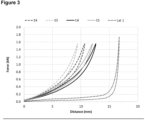
- the pure insert shows the behaviour of a very flexible foam, i.e. the material shows an high compression even at low forces and at even higher compression a sudden increases in stiffness.
- the lattice (Lat 1) already shows a high "stiffness I” and a much higher “stiffness II” compared to the E-TPU (C4 and C5).
- the combination of E-TPU and lattice shows a similar force deflection curve as the pure E-TPU, whereby the "stiffness I" hardly changes compared to the E-TPU, i.e. one would have the same feeling when putting on a shoe.
- a higher "stiffness II" can be achieved with the same density.
Landscapes
- Engineering & Computer Science (AREA)
- Mechanical Engineering (AREA)
- Chemical & Material Sciences (AREA)
- Materials Engineering (AREA)
- Manufacturing & Machinery (AREA)
- Physics & Mathematics (AREA)
- Optics & Photonics (AREA)
- Manufacture Of Porous Articles, And Recovery And Treatment Of Waste Products (AREA)
- Laminated Bodies (AREA)
- Footwear And Its Accessory, Manufacturing Method And Apparatuses (AREA)
- Molding Of Porous Articles (AREA)
Applications Claiming Priority (3)
| Application Number | Priority Date | Filing Date | Title |
|---|---|---|---|
| EP20208235 | 2020-11-17 | ||
| PCT/EP2021/081565 WO2022106319A1 (en) | 2020-11-17 | 2021-11-12 | Composite article comprising a structured porous body and a foam and a process the production of a structured porous body and a particle foam |
| EP21805549.9A EP4247610B1 (de) | 2020-11-17 | 2021-11-12 | Verbundartikel mit einem strukturierten porösen körper und einem schaumstoff und verfahren zur herstellung eines strukturierten porösen körpers und eines partikelschaumstoffs |
Related Parent Applications (2)
| Application Number | Title | Priority Date | Filing Date |
|---|---|---|---|
| EP21805549.9A Division-Into EP4247610B1 (de) | 2020-11-17 | 2021-11-12 | Verbundartikel mit einem strukturierten porösen körper und einem schaumstoff und verfahren zur herstellung eines strukturierten porösen körpers und eines partikelschaumstoffs |
| EP21805549.9A Division EP4247610B1 (de) | 2020-11-17 | 2021-11-12 | Verbundartikel mit einem strukturierten porösen körper und einem schaumstoff und verfahren zur herstellung eines strukturierten porösen körpers und eines partikelschaumstoffs |
Publications (2)
| Publication Number | Publication Date |
|---|---|
| EP4494854A2 true EP4494854A2 (de) | 2025-01-22 |
| EP4494854A3 EP4494854A3 (de) | 2025-03-26 |
Family
ID=73475916
Family Applications (2)
| Application Number | Title | Priority Date | Filing Date |
|---|---|---|---|
| EP24210936.1A Withdrawn EP4494854A3 (de) | 2020-11-17 | 2021-11-12 | Verbundartikel mit einem strukturierten porösen körper und einem schaum und verfahren zur herstellung eines strukturierten porösen körpers und eines partikelschaums |
| EP21805549.9A Active EP4247610B1 (de) | 2020-11-17 | 2021-11-12 | Verbundartikel mit einem strukturierten porösen körper und einem schaumstoff und verfahren zur herstellung eines strukturierten porösen körpers und eines partikelschaumstoffs |
Family Applications After (1)
| Application Number | Title | Priority Date | Filing Date |
|---|---|---|---|
| EP21805549.9A Active EP4247610B1 (de) | 2020-11-17 | 2021-11-12 | Verbundartikel mit einem strukturierten porösen körper und einem schaumstoff und verfahren zur herstellung eines strukturierten porösen körpers und eines partikelschaumstoffs |
Country Status (7)
| Country | Link |
|---|---|
| US (1) | US12643269B2 (de) |
| EP (2) | EP4494854A3 (de) |
| JP (1) | JP2023552080A (de) |
| KR (1) | KR20230109143A (de) |
| CN (1) | CN116438046A (de) |
| ES (1) | ES3016136T3 (de) |
| WO (1) | WO2022106319A1 (de) |
Families Citing this family (2)
| Publication number | Priority date | Publication date | Assignee | Title |
|---|---|---|---|---|
| TWI752623B (zh) * | 2019-09-13 | 2022-01-11 | 美商北面服飾公司 | 三維發泡體替代品 |
| CN118359837B (zh) * | 2024-06-19 | 2024-08-16 | 浙江新恒泰新材料股份有限公司 | 一种高回弹聚烯烃发泡材料及其制备方法 |
Citations (13)
| Publication number | Priority date | Publication date | Assignee | Title |
|---|---|---|---|---|
| US4863538A (en) | 1986-10-17 | 1989-09-05 | Board Of Regents, The University Of Texas System | Method and apparatus for producing parts by selective sintering |
| WO1994020568A1 (de) | 1993-03-11 | 1994-09-15 | Basf Aktiengesellschaft | Schaumstoffe auf basis thermoplastischer polyurethane |
| US5647931A (en) | 1994-01-11 | 1997-07-15 | Eos Gmbh Electro Optical Systems | Method and apparatus for producing a three-dimensional object |
| US5658412A (en) | 1993-01-11 | 1997-08-19 | Eos Gmbh Electro Optical Systems | Method and apparatus for producing a three-dimensional object |
| WO2007082838A1 (de) | 2006-01-18 | 2007-07-26 | Basf Se | Schaumstoffe auf basis thermoplastischer polyurethane |
| WO2010010010A1 (de) | 2008-07-25 | 2010-01-28 | Basf Se | Thermoplastische polymer blends auf der basis von thermoplastischem polyurethan und styrolpolymerisat, daraus hergestellte schaumstoffe und zugehörige herstellungsverfahren |
| WO2013153190A1 (de) | 2012-04-13 | 2013-10-17 | Basf Se | Verfahren zur herstellung von expandiertem granulat |
| WO2015108543A1 (en) | 2014-01-16 | 2015-07-23 | Hewlett-Packard Development Company, L.P. | Three-dimensional (3d) printing method |
| US20160324260A1 (en) | 2015-05-08 | 2016-11-10 | Under Armour, Inc. | Midsole lattice with hollow tubes for footwear |
| WO2017030835A1 (en) | 2015-08-19 | 2017-02-23 | Nike Innovate C.V. | Process for preparing thermoplastic elastomer foam and foamed article |
| EP3292795A1 (de) | 2016-09-13 | 2018-03-14 | Covestro Deutschland AG | Verwendung eines elastischen polymers zur herstellung eines porösen körpers in einem verfahren zur generativen fertigung |
| CN109688877A (zh) | 2016-09-13 | 2019-04-26 | 科思创德国股份有限公司 | 多孔体、用于该多孔体的增材制造法和用于支撑和/或支承人体的装置 |
| US20190357695A1 (en) | 2016-09-23 | 2019-11-28 | Covestro Deutschland Ag | Composite object comprising a body and a foam, and method for production thereof |
Family Cites Families (23)
| Publication number | Priority date | Publication date | Assignee | Title |
|---|---|---|---|---|
| JPS5413980U (de) * | 1977-06-30 | 1979-01-29 | ||
| DE3400909A1 (de) * | 1984-01-12 | 1985-09-05 | Trix Mangold GmbH, 8510 Fürth | Rueckmeldeeinrichtung fuer weichenantriebe o.dgl. |
| DE4008173A1 (de) * | 1990-03-15 | 1991-09-19 | Philippine Tech Kunststoff | Verkleidungselement und verfahren zu seiner herstellung |
| DE19823415A1 (de) | 1998-05-26 | 1999-12-16 | Behr Gmbh & Co | Verfahren zum Herstellen eines Schaumstoffkörpers |
| FR2812234B1 (fr) | 2000-07-27 | 2003-05-16 | Isobox Technologies | Procede de fabrication d'une piece a base de polystyrene expanse destinee a supporter une charge et piece ainsi obtenue |
| GB2381491B (en) * | 2001-10-30 | 2005-02-02 | Trysome Ltd | Forming composite structures |
| DE102007024311A1 (de) * | 2007-05-24 | 2008-11-27 | GM Global Technology Operations, Inc., Detroit | Schaumstoffelement |
| FR2919238B1 (fr) | 2007-07-25 | 2009-10-23 | Cera | Element de garnissage de siege de vehicule automobile comprenant un bloc en polyolefine expansee a face d'aspect grainee. |
| CH706241B1 (de) | 2012-03-29 | 2015-11-30 | Sager Ag | Verfahren zur Herstellung einer Schaumstoffplatte |
| US9456696B2 (en) | 2013-11-29 | 2016-10-04 | Zinus, Inc. | Foam furniture molded around a core with a lumbar support protrusion |
| EP3693146B1 (de) | 2014-11-05 | 2023-03-01 | NIKE Innovate C.V. | Verfahren und flexible gitterschaumstoffe |
| US10427336B2 (en) | 2014-11-20 | 2019-10-01 | Baker Hughes, A Ge Company, Llc | Periodic structured composite and articles therefrom |
| AT518100A1 (de) * | 2015-12-22 | 2017-07-15 | Fill Gmbh | Verfahren zur Herstellung eines Formkörpers aus einem Partikelschaummaterial |
| DE102016007913B4 (de) | 2016-06-30 | 2018-08-23 | Krallmann Kunststoffverarbeitung Gmbh | Kfz-Verbundbauteil und Verfahren zu seiner Herstellung |
| DE102016223567A1 (de) * | 2016-11-28 | 2018-05-30 | Adidas Ag | Verfahren zur Herstellung von Sportartikeln und Sportartikel |
| US10932521B2 (en) | 2017-03-27 | 2021-03-02 | Adidas Ag | Footwear midsole with warped lattice structure and method of making the same |
| US10064726B1 (en) * | 2017-04-18 | 2018-09-04 | Warsaw Orthopedic, Inc. | 3D printing of mesh implants for bone delivery |
| JP6844065B2 (ja) | 2018-04-09 | 2021-03-17 | 旭化成株式会社 | 発泡成型体、及びその製造方法 |
| JP7132489B2 (ja) * | 2018-04-27 | 2022-09-07 | キョーラク株式会社 | 構造体の製造方法及びパネル |
| JP7389026B2 (ja) * | 2018-06-05 | 2023-11-29 | 株式会社アーケム | 多孔質構造体、多孔質構造体の製造方法、及び、3d造形用データ |
| AT521642B1 (de) | 2018-09-13 | 2021-08-15 | Blue Danube Robotics Gmbh | Verfahren zur Herstellung eines Polsters |
| WO2021169804A1 (zh) * | 2020-02-26 | 2021-09-02 | 初石智能科技(上海)有限公司 | 鞋中底、鞋类制品、三维数据处理方法、3d打印方法 |
| CN113303549A (zh) * | 2020-02-26 | 2021-08-27 | 初石智能科技(上海)有限公司 | 鞋中底、鞋类制品、三维数据处理方法、3d打印方法 |
-
2021
- 2021-11-12 KR KR1020237016568A patent/KR20230109143A/ko active Pending
- 2021-11-12 EP EP24210936.1A patent/EP4494854A3/de not_active Withdrawn
- 2021-11-12 ES ES21805549T patent/ES3016136T3/es active Active
- 2021-11-12 CN CN202180077234.4A patent/CN116438046A/zh active Pending
- 2021-11-12 EP EP21805549.9A patent/EP4247610B1/de active Active
- 2021-11-12 US US18/037,095 patent/US12643269B2/en active Active
- 2021-11-12 WO PCT/EP2021/081565 patent/WO2022106319A1/en not_active Ceased
- 2021-11-12 JP JP2023528705A patent/JP2023552080A/ja active Pending
Patent Citations (13)
| Publication number | Priority date | Publication date | Assignee | Title |
|---|---|---|---|---|
| US4863538A (en) | 1986-10-17 | 1989-09-05 | Board Of Regents, The University Of Texas System | Method and apparatus for producing parts by selective sintering |
| US5658412A (en) | 1993-01-11 | 1997-08-19 | Eos Gmbh Electro Optical Systems | Method and apparatus for producing a three-dimensional object |
| WO1994020568A1 (de) | 1993-03-11 | 1994-09-15 | Basf Aktiengesellschaft | Schaumstoffe auf basis thermoplastischer polyurethane |
| US5647931A (en) | 1994-01-11 | 1997-07-15 | Eos Gmbh Electro Optical Systems | Method and apparatus for producing a three-dimensional object |
| WO2007082838A1 (de) | 2006-01-18 | 2007-07-26 | Basf Se | Schaumstoffe auf basis thermoplastischer polyurethane |
| WO2010010010A1 (de) | 2008-07-25 | 2010-01-28 | Basf Se | Thermoplastische polymer blends auf der basis von thermoplastischem polyurethan und styrolpolymerisat, daraus hergestellte schaumstoffe und zugehörige herstellungsverfahren |
| WO2013153190A1 (de) | 2012-04-13 | 2013-10-17 | Basf Se | Verfahren zur herstellung von expandiertem granulat |
| WO2015108543A1 (en) | 2014-01-16 | 2015-07-23 | Hewlett-Packard Development Company, L.P. | Three-dimensional (3d) printing method |
| US20160324260A1 (en) | 2015-05-08 | 2016-11-10 | Under Armour, Inc. | Midsole lattice with hollow tubes for footwear |
| WO2017030835A1 (en) | 2015-08-19 | 2017-02-23 | Nike Innovate C.V. | Process for preparing thermoplastic elastomer foam and foamed article |
| EP3292795A1 (de) | 2016-09-13 | 2018-03-14 | Covestro Deutschland AG | Verwendung eines elastischen polymers zur herstellung eines porösen körpers in einem verfahren zur generativen fertigung |
| CN109688877A (zh) | 2016-09-13 | 2019-04-26 | 科思创德国股份有限公司 | 多孔体、用于该多孔体的增材制造法和用于支撑和/或支承人体的装置 |
| US20190357695A1 (en) | 2016-09-23 | 2019-11-28 | Covestro Deutschland Ag | Composite object comprising a body and a foam, and method for production thereof |
Non-Patent Citations (2)
| Title |
|---|
| BRÜCKNER ET AL.: "Polyurethane-foam midsoles in running shoes - Impact energy and damping", PROCEDIA ENGINEERING |
| J. B. OSTOS ET AL.: "The formation and stabilization of lattice structures via foam addition", ACTA MATERIALIA, 2012 |
Also Published As
| Publication number | Publication date |
|---|---|
| US20230339152A1 (en) | 2023-10-26 |
| EP4247610A1 (de) | 2023-09-27 |
| EP4247610B1 (de) | 2025-01-08 |
| EP4247610C0 (de) | 2025-01-08 |
| EP4494854A3 (de) | 2025-03-26 |
| US12643269B2 (en) | 2026-06-02 |
| ES3016136T3 (en) | 2025-05-08 |
| WO2022106319A1 (en) | 2022-05-27 |
| CN116438046A (zh) | 2023-07-14 |
| JP2023552080A (ja) | 2023-12-14 |
| KR20230109143A (ko) | 2023-07-19 |
Similar Documents
| Publication | Publication Date | Title |
|---|---|---|
| EP4247610B1 (de) | Verbundartikel mit einem strukturierten porösen körper und einem schaumstoff und verfahren zur herstellung eines strukturierten porösen körpers und eines partikelschaumstoffs | |
| EP3384797B1 (de) | Element für schuhsohlen und schuhe | |
| EP0955211B1 (de) | Aufprallenergieabsorbierende Verbundmaterialien | |
| US20190345284A1 (en) | Expanded thermoplastic polyurethane beads, production thereof and production of a molded part | |
| EP3578068A1 (de) | Sohlenelement und schuh | |
| KR20140073592A (ko) | 차량 시트 쿠션 | |
| WO2021014371A1 (en) | Expanded beads having density and/or cell morphology gradients, and sintered foams obtained therefrom | |
| WO2021089767A1 (en) | 3d printed customised cupsoles | |
| US20260061671A1 (en) | COMFORT eTPU | |
| DE69530820T2 (de) | Stossabsorbierendes Material und Fahrzeugsitz aus diesem Material | |
| EP3464435B1 (de) | Hohlpartikel aus thermoplastischen elastomeren und poröse formkörper | |
| EP3753717A1 (de) | Verfahren zur herstellung eines harzformkörpers und schuhsohlenelement | |
| US20070105969A1 (en) | Multi-density flexible foam | |
| Davidson | Investigating the suitability of laser sintered elastomers for running footwear applications | |
| Hartings et al. | Fatigue investigation of urethane seat pads | |
| US11364862B2 (en) | Shock absorption bumper and manufacturing method thereof | |
| EP4697999A1 (de) | Geschäumte schuhkomponente | |
| US20010012554A1 (en) | Energy-absorbing component and method of producing the same | |
| WO2024089264A1 (en) | Expanded thermoplastic polyurethane for special molding process | |
| Kamaruddin et al. | Characterisation of Deproteinised Natural Rubber Latex Foam for Enhanced Acoustic and Vibration Isolation | |
| Ford | Characterization of 3D Printed Thermoplastic Elastomer Auxetic for Impact Tunable Midsole Sport Applications | |
| WO2022161981A1 (en) | Composite material for a molded body |
Legal Events
| Date | Code | Title | Description |
|---|---|---|---|
| PUAI | Public reference made under article 153(3) epc to a published international application that has entered the european phase |
Free format text: ORIGINAL CODE: 0009012 |
|
| STAA | Information on the status of an ep patent application or granted ep patent |
Free format text: STATUS: THE APPLICATION HAS BEEN PUBLISHED |
|
| AC | Divisional application: reference to earlier application |
Ref document number: 4247610 Country of ref document: EP Kind code of ref document: P |
|
| AK | Designated contracting states |
Kind code of ref document: A2 Designated state(s): AL AT BE BG CH CY CZ DE DK EE ES FI FR GB GR HR HU IE IS IT LI LT LU LV MC MK MT NL NO PL PT RO RS SE SI SK SM TR |
|
| REG | Reference to a national code |
Ref country code: DE Ref legal event code: R079 Free format text: PREVIOUS MAIN CLASS: B29C0067200000 Ipc: B29C0044120000 |
|
| PUAL | Search report despatched |
Free format text: ORIGINAL CODE: 0009013 |
|
| AK | Designated contracting states |
Kind code of ref document: A3 Designated state(s): AL AT BE BG CH CY CZ DE DK EE ES FI FR GB GR HR HU IE IS IT LI LT LU LV MC MK MT NL NO PL PT RO RS SE SI SK SM TR |
|
| RIC1 | Information provided on ipc code assigned before grant |
Ipc: B29C 67/20 20060101ALI20250218BHEP Ipc: B29C 64/153 20170101ALI20250218BHEP Ipc: B29C 44/44 20060101ALI20250218BHEP Ipc: B29C 44/34 20060101ALI20250218BHEP Ipc: B29C 44/12 20060101AFI20250218BHEP |
|
| RAP1 | Party data changed (applicant data changed or rights of an application transferred) |
Owner name: STRATASYS, INC. |
|
| STAA | Information on the status of an ep patent application or granted ep patent |
Free format text: STATUS: THE APPLICATION IS DEEMED TO BE WITHDRAWN |
|
| 18D | Application deemed to be withdrawn |
Effective date: 20250927 |