EP4495003A1 - Adaptateur de chargement externe destiné à être utilisé avec un giravion - Google Patents
Adaptateur de chargement externe destiné à être utilisé avec un giravion Download PDFInfo
- Publication number
- EP4495003A1 EP4495003A1 EP23186704.5A EP23186704A EP4495003A1 EP 4495003 A1 EP4495003 A1 EP 4495003A1 EP 23186704 A EP23186704 A EP 23186704A EP 4495003 A1 EP4495003 A1 EP 4495003A1
- Authority
- EP
- European Patent Office
- Prior art keywords
- external cargo
- adapter
- rope
- cargo
- human
- Prior art date
- Legal status (The legal status is an assumption and is not a legal conclusion. Google has not performed a legal analysis and makes no representation as to the accuracy of the status listed.)
- Withdrawn
Links
Images


Classifications
-
- B—PERFORMING OPERATIONS; TRANSPORTING
- B64—AIRCRAFT; AVIATION; COSMONAUTICS
- B64D—EQUIPMENT FOR FITTING IN OR TO AIRCRAFT; FLIGHT SUITS; PARACHUTES; ARRANGEMENT OR MOUNTING OF POWER PLANTS OR PROPULSION TRANSMISSIONS IN AIRCRAFT
- B64D1/00—Dropping, ejecting, releasing or receiving articles, liquids, or the like, in flight
- B64D1/02—Dropping, ejecting, or releasing articles
- B64D1/08—Dropping, ejecting, or releasing articles the articles being load-carrying devices
-
- B—PERFORMING OPERATIONS; TRANSPORTING
- B64—AIRCRAFT; AVIATION; COSMONAUTICS
- B64D—EQUIPMENT FOR FITTING IN OR TO AIRCRAFT; FLIGHT SUITS; PARACHUTES; ARRANGEMENT OR MOUNTING OF POWER PLANTS OR PROPULSION TRANSMISSIONS IN AIRCRAFT
- B64D1/00—Dropping, ejecting, releasing or receiving articles, liquids, or the like, in flight
- B64D1/22—Taking-up articles from earth's surface
-
- B—PERFORMING OPERATIONS; TRANSPORTING
- B64—AIRCRAFT; AVIATION; COSMONAUTICS
- B64D—EQUIPMENT FOR FITTING IN OR TO AIRCRAFT; FLIGHT SUITS; PARACHUTES; ARRANGEMENT OR MOUNTING OF POWER PLANTS OR PROPULSION TRANSMISSIONS IN AIRCRAFT
- B64D7/00—Arrangement of military equipment, e.g. armaments, armament accessories or military shielding, in aircraft; Adaptations of armament mountings for aircraft
- B64D7/02—Arrangement of military equipment, e.g. armaments, armament accessories or military shielding, in aircraft; Adaptations of armament mountings for aircraft the armaments being firearms
- B64D7/06—Arrangement of military equipment, e.g. armaments, armament accessories or military shielding, in aircraft; Adaptations of armament mountings for aircraft the armaments being firearms movably mounted
-
- B—PERFORMING OPERATIONS; TRANSPORTING
- B64—AIRCRAFT; AVIATION; COSMONAUTICS
- B64C—AEROPLANES; HELICOPTERS
- B64C27/00—Rotorcraft; Rotors peculiar thereto
- B64C27/22—Compound rotorcraft, i.e. aircraft using in flight the features of both aeroplane and rotorcraft
- B64C27/26—Compound rotorcraft, i.e. aircraft using in flight the features of both aeroplane and rotorcraft characterised by provision of fixed wings
-
- B—PERFORMING OPERATIONS; TRANSPORTING
- B64—AIRCRAFT; AVIATION; COSMONAUTICS
- B64U—UNMANNED AERIAL VEHICLES [UAV]; EQUIPMENT THEREFOR
- B64U2101/00—UAVs specially adapted for particular uses or applications
- B64U2101/55—UAVs specially adapted for particular uses or applications for life-saving or rescue operations; for medical use
- B64U2101/58—UAVs specially adapted for particular uses or applications for life-saving or rescue operations; for medical use for medical evacuation, i.e. the transportation of persons or animals to a place where they can receive medical care
-
- B—PERFORMING OPERATIONS; TRANSPORTING
- B64—AIRCRAFT; AVIATION; COSMONAUTICS
- B64U—UNMANNED AERIAL VEHICLES [UAV]; EQUIPMENT THEREFOR
- B64U2101/00—UAVs specially adapted for particular uses or applications
- B64U2101/60—UAVs specially adapted for particular uses or applications for transporting passengers; for transporting goods other than weapons
- B64U2101/61—UAVs specially adapted for particular uses or applications for transporting passengers; for transporting goods other than weapons for transporting passengers
-
- B—PERFORMING OPERATIONS; TRANSPORTING
- B64—AIRCRAFT; AVIATION; COSMONAUTICS
- B64U—UNMANNED AERIAL VEHICLES [UAV]; EQUIPMENT THEREFOR
- B64U2101/00—UAVs specially adapted for particular uses or applications
- B64U2101/60—UAVs specially adapted for particular uses or applications for transporting passengers; for transporting goods other than weapons
- B64U2101/67—UAVs specially adapted for particular uses or applications for transporting passengers; for transporting goods other than weapons the UAVs comprising tethers for lowering the goods
Definitions
- the present invention is related to an external cargo adapter for use with a rotorcraft that comprises at least one carrier station, in particular at least one weapon station.
- the present invention is further related to a human external cargo transportation arrangement for use with such a rotorcraft, as well as to a human external cargo transportation system.
- Rotorcrafts which comprise at least one carrier station, in particular at least one weapon station for carrying weapons externally, are well-known.
- the documents US 2020/0298974 A1 , US 2004/0216596 A1 , and EP 3 909 580 A1 illustrate and/or describe such rotorcrafts, which may also be referred to as "attack helicopters".
- attack helicopters are usually not equipped for transporting on their outside human and/or non-human external cargo in general. Therefore, for instance human external cargo that should be transported with a given attack helicopter is usually e. g. transported on a landing gear and/or one or more stub wings of the given attack helicopter.
- the document US 2022/0169389 A1 describes an attack helicopter that may be adapted for human external cargo transportation.
- This attack helicopter comprises a modular deployable external passenger system (MDEPS) that mounts to the bomb release unit (BRU) and air launched effect (ALE) launcher rack of the attack helicopter.
- the MDEPS includes a fully internally stowable external passenger seating unit with a plurality of seats, which is affixed to articulating mounts.
- the external passenger seating unit may be translated between a first position in which the external passenger seating unit is stowed in a payload bay of the attack helicopter and a second position in which the external passenger seating unit is deployed external to the attack helicopter for accommodating at least one passenger.
- the document WO 2005/039972 A2 describes a rotorcraft with a fuselage and pivotable lateral payload bays mounted thereto.
- the pivotable lateral payload bays may be used for mounting or transporting guns or ammunition, personnel or troops, or cargo in general. They may also be used for evacuating wounded persons, and so on.
- human and/or non-human cargo attachment devices for use with suitably equipped rotorcrafts, which are embodied to permit transport of human and/or non-human external cargo outside of the rotorcraft, are available in a wide range of variations and usually attachable to ropes or cables which may be connected to the rotorcrafts.
- three different types of human and/or non-human cargo attachment devices are currently available: rigging plates or loops of so-called SPIE (Special Patrol I nsertion/ E xtraction) rigs, personal transport nets, and personal transport platforms, all of which are attachable to associated attachment interfaces such as safety hooks or snap hooks provided at associated ropes or cables of rotorcrafts.
- an object of the present invention to enable use of an attack helicopter for human and/or non-human external cargo transportation and, more generally, of a rotorcraft which comprises at least one carrier station, in particular at least one weapon station for carrying weapons externally.
- an external cargo adapter for use with a rotorcraft that comprises at least one carrier station, in particular at least one weapon station, the external cargo adapter comprising the features of claim 1. More specifically, according to the present invention the external cargo adapter comprises at least one mounting lug for attachment to the at least one carrier station, at least one cargo carrying ring for connection to a connecting rope adapted for transport of an external cargo, and a connecting member that connects the at least one mounting lug with the at least one cargo carrying ring.
- the external cargo adapter enables use of the at least one carrier station of the rotorcraft, in particular the at least one weapon station that is conventionally used for carrying weapons, for transport of human and/or non-human external cargo.
- the external cargo adapter is lightweight and can be carried in the rotorcraft. It may be used without provision of any additional external mechanics on the rotorcraft, such as an additional cargo hook or winch.
- the inventive external cargo adapter is suitable for attachment of comparatively simple and easy to use human external cargo transportation devices and, thus, enables e. g. evacuation of persons out of dangerous areas. Accordingly, a reliable way of evacuating persons from dangerous areas using already existing rotorcraft interfaces may be provided. Thereby, the persons may be picked up with the rotorcraft without a need for landing, which is important for forest areas, unprepared terrain or water.
- the inventive external cargo adapter is a removable component which is removably attachable to the at least one carrier station via two connector rings. These two rings implement an opening mechanism.
- the removable component further comprises an attachment for human external cargo.
- a swivel may also be installed on the removable component. The swivel may e. g. be used for attachment of suitable transporting ropes.
- the inventive external cargo adapter does not require any fuselage modification and/or modifications to the at least one carrier station, i. e. the at least one weapon station, of the rotorcraft. Accordingly, there is no need for a design change to the rotorcraft.
- the external cargo adapter may be attached easily and quickly to the at least one carrier station, i. e. the at least one weapon station, and it may likewise be released easily and quickly, if required.
- the at least one mounting lug comprises an associated lug opening configured for receiving a blocking hook or bar of the at least one carrier station.
- the at least one cargo carrying ring is mounted to the connecting member via a swivel.
- the connecting member is a connecting rail.
- the external cargo adapter may further comprise a first mounting lug and a second mounting lug which are spaced apart from each other on the connecting rail.
- the first and second mounting lugs and the at least one cargo carrying ring may be mounted to opposite sides of the connecting rail.
- a human external cargo transportation arrangement for use with a rotorcraft that comprises at least a first carrier station and a second carrier station, in particular at least a first weapon station and a second weapon station, is provided.
- the human external cargo transportation arrangement comprises a first external cargo adapter as described hereinabove for attachment to the first carrier station, a second external cargo adapter as described hereinabove for attachment to the second carrier station, a first connecting rope for connection to the first external cargo adapter, and a second connecting rope for connection to the second external cargo adapter.
- Each one of the first and second connecting ropes is connected to a swivel for connection to at least one first human external cargo attachment rope and one second human external cargo attachment rope.
- persons which should be transported as human external cargo with the rotorcraft using the human external cargo transportation arrangement may attach themselves to the rotorcraft over a harness with a swivel in order to allow rotation during flight in order to prevent twisting of the first and second human external cargo attachment ropes and, thus, of the first and second connecting ropes.
- the swivel may e. g. be positioned on a top end or a bottom end of the first and second connecting ropes.
- more than one swivel is used in the human external cargo transportation arrangement to allow rotation of the human external cargo before and after releasing of one attachment path.
- the human external cargo transportation arrangement may be stored inside of the rotorcraft or on one carrier station, i. e. weapon station, in a suitable box that is attachable thereto e. g. using the external cargo adapter described above.
- all remaining carrier stations, i. e. weapon stations may be used for transportation of weapons or other stores before a human external cargo operation, which may require two or more external cargo adapters described hereinabove.
- the human external cargo transportation arrangement is adapted for creating a redundant connection between the first carrier station and the second carrier station of a rotorcraft.
- this redundant connection if e. g. attachment to the first carrier station fails accidentally or intentionally, for instance due to a defective cargo hook, attachment to the second carrier station still guarantees safety of a respectively transported person.
- the applicable FAR regulations for transportation of human external cargo are largely met and the safety of transported persons is increased compared to a transportation on the landing gear or stub wings as described above.
- conventional human cargo attachment devices such as SPIE rigs, the human external cargo transportation arrangement provides for the same level of safety.
- two similar loaded ropes implementing the first and second connecting ropes may be attached via the first and second external cargo adapters to the first and second carrier stations, respectively.
- the first and second carrier stations are each provided on an associated stub wing of the rotorcraft.
- the first and second connecting ropes are interconnected by means of a swivel.
- Persons which are to be transported may, thus, attach themselves to the swivel using e. g. a suitable personnel-carrying device system (PCDS) that may also be referred to as "securing harness".
- PCDS personnel-carrying device system
- two securing harnesses would be used, which implement or comprise the first and second human external cargo attachment ropes that may have different lengths.
- the swivel enables rotation of the persons which are to be transported during normal operation.
- the persons which are to be transported switch from two connection points to only one connection point.
- transportation is still possible and rotating movements are still allowed by the swivel.
- the released one of the first and second external cargo adapters is not lost and still attached via the respective one of the first and second connecting ropes to the swivel.
- first and second connecting ropes may again be attached via the first and second external cargo adapters to the first and second carrier stations, respectively.
- the first and second carrier stations are each again provided on an associated stub wing of the rotorcraft.
- first and second connecting ropes may now be connected to first and second swivels, respectively.
- first and second redundant ropes may now be attached to the first and second swivels, respectively, and to the first and second external cargo adapters, respectively.
- the first and second external cargo adapters may now be interconnected via a safety rope.
- first and second swivels enable rotation of the persons which are to be transported during normal operation.
- the safety rope ensures after the release a small falling height of the released one of the first and second external cargo adapters in order not to injure the other person upon release.
- first or second swivel In any case transportation is still possible and rotating movements are still allowed by the first or second swivel. Furthermore, the released one of the first and second external cargo adapters is not lost and still at least attached to the safety rope.
- first and second connecting ropes may be attached via a total of four external cargo adapters to four carrier stations, respectively.
- first and second carrier stations are provided on an associated stub wing of the rotorcraft
- second and third carrier stations are provided on another stub wing of the rotorcraft.
- the first and second connecting ropes are connected to first and second swivels, respectively. Persons which are to be transported may, thus, attach themselves to the first swivel or the second swivel using e. g. a suitable securing harness.
- the first and second swivels enable rotation of the persons which are to be transported during normal operation.
- the rotorcraft is still symmetrically loaded. Nevertheless, only a single person may be transported on each one of the stub wings and is attached to only one of the stub wings.
- the first and second connecting ropes are connected to a single swivel that attaches the first connecting rope to the second connecting rope.
- the first connecting rope is connected to a first swivel for connection to the second human external cargo attachment rope
- the second connecting rope is connected to a second swivel for connection to the first human external cargo attachment rope.
- the first swivel is further connected to a first redundant rope provided for connection to the second external cargo adapter
- the second swivel is further connected to a second redundant rope provided for connection to the first external cargo adapter.
- the human external cargo transportation arrangement may further comprise a safety rope for connection of the first external cargo adapter with the second external cargo adapter.
- the human external cargo transportation arrangement may comprise a third external cargo adapter as described hereinabove for attachment to a third carrier station of the rotorcraft, and a fourth external cargo adapter as described hereinabove for attachment to a fourth carrier station of the rotorcraft.
- the first connecting rope is a first Y-rope for connection to the first external cargo adapter and the third external cargo adapter
- the second connecting rope is a second Y-rope for connection to the second external cargo adapter and the fourth external cargo adapter.
- the human external cargo transportation system comprises a rotorcraft with at least one carrier station, in particular at least one weapon station, and a human external cargo transportation arrangement as described hereinabove.
- the rotorcraft comprises a wing arrangement with at least one left-hand side wing and one right-hand side wing.
- the left-hand side wing comprises at least the first carrier station
- the right-hand side wing comprises at least the second carrier station.
- the wing arrangement may be a stub wing arrangement, wherein the left-hand side wing and the right-hand side wing are stub wings.
- the rotorcraft is an attack helicopter.
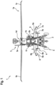
- FIG. 1 shows a rotorcraft 1 that is, by way of example, embodied as a helicopter and, more particularly, as a so-called attack helicopter.
- the rotorcraft 1 is hereinafter referred to as the "attack helicopter 1".
- the present invention is, however, not limited to attack helicopters and may likewise be applied to any other rotorcraft that is adapted for vertical takeoff and landing.
- the attack helicopter 1 comprises at least one rotor 1a that may be powered by two engines 1e, 1f for providing lift and forward or backward thrust during operation.
- the at least one rotor 1a is a multi-blade main rotor that comprises a plurality of rotor blades which are connected at a rotor head 1d to an associated rotor shaft that rotates in operation of the attack helicopter 1 about an associated rotor axis.
- Two rotor blades of the plurality of rotor blades are illustratively separately labelled with the reference signs 1b, 1c.
- the attack helicopter 1 preferably comprises a fuselage 2 to which a landing gear 5 of the wheel-type may be attached.
- the fuselage 2 forms an aircraft interior region that accommodates at least a cockpit 2a.
- the attack helicopter 1 preferably comprises at least one counter-torque device 3 configured to provide counter-torque during operation, i. e. to counter the torque created by rotation of the at least one rotor 1a for purposes of balancing the attack helicopter 1 in terms of yaw.
- the at least one counter-torque device 3 is illustratively provided at an aft section of the attack helicopter 1 and preferably comprises a tail rotor 3a.
- the aft section of the attack helicopter 1 may further be provided with a horizontal stabilizer 4.
- the attack helicopter 1 may be provided with a tail boom to which the counter-torque device 3 and the horizontal stabilizer 4 are mounted.
- the attack helicopter 1 further comprises a wing arrangement 6. More specifically, the wing arrangement 6 comprises two separate wings 6a, 6b.
- the wing 6a is a left-hand side wing, seen in forward flight direction of the attack helicopter 1, and the wing 6b is a right-hand side wing, seen in forward flight direction of the attack helicopter 1.
- the wing arrangement 6 is a stub wing arrangement, wherein the wing 6a is a left-hand side stub wing and wherein the wing 6b is a right-hand side stub wing.
- the stub wing arrangement 6 is equipped with associated carrier stations 7, 8.
- the left-hand side stub wing 6a is equipped with an outboard sub wing carrier station 7a and an inboard sub wing carrier station 7b
- the right-hand side stub wing 6b is equipped with an outboard sub wing carrier station 8a and an inboard sub wing carrier station 8b.
- the present invention is not limited to provision of the carrier stations 7, 8 as sub wing carrier stations on the stub wing arrangement 6.
- the carrier stations 7, 8 or other suitable carrier stations may e. g. be provided on an underside of the fuselage 2, or they may be attached to the landing gear 5, and so on.
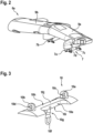
- Figure 2 shows the left-hand stub wing 6a of Figure 1 with the carrier stations 7 which comprise the outboard sub wing carrier station 7a and the inboard sub wing carrier station 7b of Figure 1 .
- the outboard sub wing carrier station 7a is mounted to an outboard section 9a of the left-hand stub wing 6a and the inboard sub wing carrier station 7b is mounted to an inboard section 9b of the left-hand stub wing 6a.
- the outboard sub wing carrier station 7a is shown with two blocking hooks or bars 7c, 7d.
- each one of the sub wing carrier stations 7a, 7b, 8a, 8b of Figure 1 preferably comprises respective blocking hooks or bars.
- the outboard sub wing carrier station 7a is preferably embodied as a weapon station which is provided for transportation of weapons or ammunition, but which may e. g. also be used for transportation of additional fuel tanks.
- a weapon station which may also be referred to as a "bomb rack” or “bomb ejector rack”, is, however, well-known to the person skilled in the art so that a detailed description of the weapon stations 7a, 7b, 8a, 8b may be omitted, for brevity and conciseness.
- FIG 3 shows an external cargo adapter 10 according to the present invention.
- the external cargo adapter 10 is provided for use with a rotorcraft that comprises at least one carrier station, in particular at least one weapon station, such as e. g. the attack helicopter 1 of Figure 1 . More specifically, the external cargo adapter 10 is preferably suitable for transportation of human and/or non-human external cargo.
- the external cargo adapter 10 comprises at least one mounting lug for attachment to an associated carrier station, e. g. one of the sub wing carrier stations 7a, 7b, 8a, 8b of Figure 1 .
- an associated carrier station e. g. one of the sub wing carrier stations 7a, 7b, 8a, 8b of Figure 1 .
- two mounting lugs 10a, 10b are provided, which may e. g. be blocked at the carrier station 7a of Figure 2 via the blocking hooks or bars 7c, 7d. Therefore, each one of the two mounting lugs 10a, 10b preferably comprises an associated lug opening 10c, 10d configured for receiving e. g. one of the blocking hooks or bars 7c, 7d.
- the external cargo adapter 10 further comprises at least one and, illustratively, exactly one cargo carrying ring 10f.
- the cargo carrying ring 10f is provided for connection to at least one connecting rope (e. g. connecting ropes 12a, 12b in Figure 4 and Figure 5 , or 16a, 16b in Figure 6 ) adapted for transport of an external cargo.
- connecting rope e. g. connecting ropes 12a, 12b in Figure 4 and Figure 5 , or 16a, 16b in Figure 6
- the cargo carrying ring 10f and the two mounting lugs 10a, 10b are connected to each other via a connecting member 10e.
- the cargo carrying ring 10f is mounted to the connecting member 10e via a swivel 10g.
- the connecting member 10e is a connecting rail 10j.
- the two mounting lugs 10a, 10b and the cargo carrying ring 10f are mounted to opposite sides 10h, 10i of the connecting rail 10j. Furthermore, the two mounting lugs 10a, 10b are preferably spaced apart from each other on the connecting rail 10j.
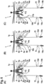
- FIG. 4 shows in parts (A) to (C) a human external cargo transportation system according to the present invention.
- the human external cargo transportation system comprises a rotorcraft with at least one carrier station, in particular at least one weapon station, and a human external cargo transportation arrangement.
- the rotorcraft is the attack helicopter 1 of Figure 1 with the carrier stations 7, 8.
- the carrier stations 7, 8 comprise the sub wing carrier stations 7a, 7b, 8a, 8b of Figure 1 which are embodied as described above at Figure 2 and arranged on the left-hand side stub wing 6a and the right-hand side stub wing 6b of the stub wing arrangement 6 of the attack helicopter 1, respectively.
- the human external cargo transportation arrangement comprises a first external cargo adapter 11a for attachment to a first carrier station, and a second external cargo adapter 11b for attachment to a second carrier station.
- Each one of the external cargo adapters 11a, 11b is preferably embodied in accordance with the external cargo adapter 10 of Figure 3 .
- the external cargo adapter 11a is attached to the sub wing carrier station 7b and the external cargo adapter 11b is attached to the sub wing carrier station 8b.
- the sub wing carrier stations 7a, 8a are kept free and may, for instance, still be used for transportation of weapons, ammunition, or additional fuel tanks.
- the human external cargo transportation arrangement further comprises a first connecting rope for connection to the external cargo adapter 11a, and a second connecting rope for connection to the external cargo adapter 11b.
- a first connecting rope 12a is attached to the external cargo adapter 11a
- a second connecting rope 12b is attached to the external cargo adapter 11b.
- connecting ropes 12a, 12b are both connected to a common swivel 13 which, thus, connects the connecting rope 12a with the connecting rope 12b.
- the common swivel 13 is provided for connection to at least one first human external cargo attachment rope and one second human external cargo attachment rope.
- a first human external cargo attachment rope 12c and a second human external cargo attachment rope 12d are attached to the common swivel 13.
- a first person 14a is attached as human external cargo to the human external cargo attachment rope 12c and a second person 14b is attached as human external cargo to the human external cargo attachment rope 12d.
- the persons 14a, 14b may, for instance, be equipped with individual securing harnesses which are provided with, or attached to, the human external cargo attachment ropes 12c, 12d.
- securing harnesses are well-known to the person skilled in the art so that a detailed description thereof can be omitted, for brevity and conciseness.
- Part (B) shows a scenario, in which the external cargo adapter 11a is accidentally or intentionally released from the sub wing carrier station 7b.
- the external cargo adapter 11a falls down by gravity below the two persons 14a, 14b, but is not lost and, instead, still attached to the common swivel 13 via the connecting rope 12a.
- both persons 14a, 14b are still attached via the human external cargo attachment ropes 12c, 12d, the common swivel 13, the connecting rope 12b, and the external cargo adapter 11b to the sub wing carrier station 8b so that a further safe transportation is guaranteed.
- Part (C) shows a scenario, in which the external cargo adapter 11b is accidentally or intentionally released from the sub wing carrier station 8b.
- the external cargo adapter 11b falls down by gravity below the two persons 14a, 14b, but is not lost and, instead, still attached to the common swivel 13 via the connecting rope 12b.
- both persons 14a, 14b are still attached via the human external cargo attachment ropes 12c, 12d, the common swivel 13, the connecting rope 12a, and the external cargo adapter 11a to the sub wing carrier station 7b so that a further safe transportation is guaranteed.
- FIG 5 shows in parts (A) to (C) a variant of the human external cargo transportation system of Figure 4 , which comprises the attack helicopter 1 and the human external cargo transportation arrangement of Figure 4 .
- the human external cargo transportation arrangement now comprises in addition to the external cargo adapters 11a, 11b, the connecting ropes 12a, 12b, the swivel 13, and the human external cargo attachment ropes 12c, 12d two redundant ropes and a safety rope.
- two separate swivels are provided instead of the single common swivel 13 of Figure 4 .
- the connecting rope 12a is now attached to a first swivel 15 and the connecting rope 12b is now attached to a second swivel, e. g. the swivel 13 of Figure 4 .
- the swivel 15 is further attached to a first redundant rope 12f that is also attached to the external cargo adapter 11b
- the swivel 13 is further attached to a second redundant rope 12e that is also attached to the external cargo adapter 11a.
- a safety rope 12g is attached to both external cargo adapters 11a, 11b and, thus, connects the external cargo adapter 11a with the external cargo adapter 11b.
- the human external cargo attachment rope 12c is attached to the swivel 13 and the human external cargo attachment rope 12d is attached to the swivel 15.
- the first person 14a is attached as human external cargo to the human external cargo attachment rope 12c and the second person 14b is attached as human external cargo to the human external cargo attachment rope 12d.
- both external cargo adapters 11a, 11b are correctly attached to the sub wing carrier stations 7b, 8b, and the sub wing carrier stations 7a, 8a are kept free and may, for instance, still be used for transportation of weapons, ammunition, or additional fuel tanks.
- Part (B) shows a scenario, in which the external cargo adapter 11a is accidentally or intentionally released from the sub wing carrier station 7b.
- the external cargo adapter 11a falls down by gravity as far as the safety rope 12g allows, but is not lost and, instead, still attached to the external cargo adapter 11b via the safety rope 12g.
- the first person 14a is still attached via the human external cargo attachment rope 12c, the swivel 13, the connecting rope 12b, and the external cargo adapter 11b to the sub wing carrier station 8b
- the second person 14b is still attached via the human external cargo attachment rope 12d, the swivel 15, the redundant rope 12f, and the external cargo adapter 11b to the sub wing carrier station 8b, so that a further safe transportation of both persons 14a, 14b is guaranteed.
- Part (C) shows a scenario, in which the external cargo adapter 11b is accidentally or intentionally released from the sub wing carrier station 8b.
- the external cargo adapter 11b falls down by gravity as far as the safety rope 12g allows, but is not lost and, instead, still attached to the external cargo adapter 11a via the safety rope 12g.
- the first person 14a is still attached via the human external cargo attachment rope 12c, the swivel 13, the redundant rope 12e, and the external cargo adapter 11a to the sub wing carrier station 7b
- the second person 14b is still attached via the human external cargo attachment rope 12d, the swivel 15, the connecting rope 12a, and the external cargo adapter 11a to the sub wing carrier station 7b, so that a further safe transportation of both persons 14a, 14b is guaranteed.
- FIG 6 shows in parts (A) to (C) another variant of the human external cargo transportation system of Figure 4 , which comprises the attack helicopter 1 with the four sub wing carrier stations 7a, 7b, 8a, 8b of Figure 4 , and the human external cargo transportation arrangement of Figure 4 .
- the human external cargo transportation arrangement now comprises two so-called Y-ropes 16a, 16b instead of the connecting ropes 12a, 12b of Figure 4 and two separate swivels are provided instead of the single common swivel 13 of Figure 4 .
- Y-ropes are well-known to the person skilled in the art so that a detailed description thereof can be omitted, for brevity and conciseness.
- two additional external cargo adapters 11c, 11d are provided. Each one of the two additional external cargo adapters 11c, 11d is preferably embodied in accordance with the external cargo adapter 10 of Figure 3 .
- the Y-rope 16a is attached to a first swivel, e. g. the swivel 15 of Figure 5
- the Y-rope 16b is attached to a second swivel, e. g. the swivel 13 of Figure 4
- the two upper branches of the Y-rope 16a which may have different lengths, are attached via the external cargo adapters 11a, 11c to the sub wing carrier stations 7b, 7a, respectively.
- the two upper branches of the Y-rope 16b which may also have different lengths, are attached via the external cargo adapters 11b, 11d to the sub wing carrier stations 8b, 8a, respectively.
- the human external cargo attachment rope 12c is attached to the swivel 13 and the human external cargo attachment rope 12d is attached to the swivel 15.
- the first person 14a is attached as human external cargo to the human external cargo attachment rope 12c and the second person 14b is attached as human external cargo to the human external cargo attachment rope 12d.
- Part (B) shows a scenario, in which the external cargo adapter 11d is accidentally or intentionally released from the sub wing carrier station 8a.
- the external cargo adapter 11d falls down by gravity as far as the respective branch of the Y-rope 16b allows, but is not lost and, instead, still attached to the external cargo adapter 11b via the Y-rope 16b.
- the first person 14a is still attached via the human external cargo attachment rope 12c, the swivel 13, the Y-rope 16b, and the external cargo adapter 11b to the sub wing carrier station 8b, so that a further safe transportation of the first person 14a is guaranteed.
- Part (C) shows a scenario, in which the external cargo adapter 11b is accidentally or intentionally released from the sub wing carrier station 8b.
- the external cargo adapter 11b falls down by gravity as far as the respective branch of the Y-rope 16b allows, but is not lost and, instead, still attached to the external cargo adapter 11d via the Y-rope 16b.
- the first person 14a is still attached via the human external cargo attachment rope 12c, the swivel 13, the Y-rope 16b, and the external cargo adapter 11d to the sub wing carrier station 8a, so that a further safe transportation of the first person 14a is guaranteed.
Landscapes
- Engineering & Computer Science (AREA)
- Aviation & Aerospace Engineering (AREA)
- Emergency Lowering Means (AREA)
Priority Applications (2)
| Application Number | Priority Date | Filing Date | Title |
|---|---|---|---|
| EP23186704.5A EP4495003A1 (fr) | 2023-07-20 | 2023-07-20 | Adaptateur de chargement externe destiné à être utilisé avec un giravion |
| US18/632,974 US20250026475A1 (en) | 2023-07-20 | 2024-04-11 | An external cargo adapter for use with a rotorcraft |
Applications Claiming Priority (1)
| Application Number | Priority Date | Filing Date | Title |
|---|---|---|---|
| EP23186704.5A EP4495003A1 (fr) | 2023-07-20 | 2023-07-20 | Adaptateur de chargement externe destiné à être utilisé avec un giravion |
Publications (1)
| Publication Number | Publication Date |
|---|---|
| EP4495003A1 true EP4495003A1 (fr) | 2025-01-22 |
Family
ID=87429698
Family Applications (1)
| Application Number | Title | Priority Date | Filing Date |
|---|---|---|---|
| EP23186704.5A Withdrawn EP4495003A1 (fr) | 2023-07-20 | 2023-07-20 | Adaptateur de chargement externe destiné à être utilisé avec un giravion |
Country Status (2)
| Country | Link |
|---|---|
| US (1) | US20250026475A1 (fr) |
| EP (1) | EP4495003A1 (fr) |
Citations (10)
| Publication number | Priority date | Publication date | Assignee | Title |
|---|---|---|---|---|
| US4378919A (en) * | 1977-07-19 | 1983-04-05 | Erickson Air Crane Co. | Apparatus for controlling orientation of a suspended load |
| EP0669277A1 (fr) * | 1994-02-28 | 1995-08-30 | Electricite De France | Elingage pour le transport de charges par hélicoptère |
| US20040216596A1 (en) | 2003-04-09 | 2004-11-04 | Isker John D. | Fixture for mounting weapons, and method of using |
| WO2005039972A2 (fr) | 2003-10-27 | 2005-05-06 | Urban Aeronautics Ltd. | Vehicules a decollage et atterrissage verticaux a soufflantes carenees |
| US20160236779A1 (en) * | 2015-02-18 | 2016-08-18 | Boost Human External Cargo Systems Inc. | Belly-mounted load beam for an aerial vehicle |
| US20180111687A1 (en) * | 2016-10-26 | 2018-04-26 | Boost Human External Cargo Systems Inc. | Belly-mounted load beam for an aerial vehicle |
| US20200298974A1 (en) | 2019-03-20 | 2020-09-24 | The Boeing Company | Auxiliary-pod mounting system and mounting methods for a helicopter |
| US20210229819A1 (en) * | 2014-06-23 | 2021-07-29 | Ascent Aerospace Ltd. | Personnel carrying devices |
| EP3909580A1 (fr) | 2018-12-11 | 2021-11-17 | Daiichi Sankyo Company, Limited | Combinaison d'un conjugué anticorps-médicament et d'un inhibiteur de parp |
| US20220169389A1 (en) | 2020-11-30 | 2022-06-02 | Bell Textron Inc. | Modular deployable external passenger system for aircraft |
Family Cites Families (31)
| Publication number | Priority date | Publication date | Assignee | Title |
|---|---|---|---|---|
| US2991960A (en) * | 1958-06-18 | 1961-07-11 | Clarence R Mcnutt | Pickup, tow and release unit |
| US3176940A (en) * | 1963-01-10 | 1965-04-06 | United Aircraft Corp | Helicopter pod positioning and supporting means |
| BE663462A (fr) * | 1964-05-13 | 1900-01-01 | ||
| US4673059A (en) * | 1982-12-20 | 1987-06-16 | Kurtgis Michael P | Placement of load onto energized transmission line system |
| US4606517A (en) * | 1983-12-12 | 1986-08-19 | Northrop Corporation | Store adapter |
| FR2670460B1 (fr) * | 1990-12-18 | 1996-11-08 | Aerospatiale | Installation de cordage sur helicoptere. |
| NZ247629A (en) * | 1992-05-15 | 1995-12-21 | Michael Paul Kurtgis Substitut | Transferring a suspended bosun chair from a helicopter to a transmission line with load detachment requiring operation of two distinct release mechanisms |
| US5593113A (en) * | 1995-02-06 | 1997-01-14 | Cox; Donald P. | Methods and apparatus for selectively attaching and releasing multiple payloads suspended from an aircraft |
| US6241185B1 (en) * | 1999-02-16 | 2001-06-05 | Paul H. Sanderson | Plank-based external aircraft armament/cargo carrying apparatus with pivotable outer end portions foldable into the aircraft cabin area |
| US6543328B1 (en) * | 2001-09-21 | 2003-04-08 | Raytheon Company | Convertible multipurpose missile launcher |
| PT2143633E (pt) * | 2008-07-10 | 2011-02-16 | Agusta Spa | Aeronave e método de recuperação de um berço de salvamento para a fuselagem do aeronave |
| DE102009030934A1 (de) * | 2009-06-23 | 2011-01-05 | Matthias Schuster | Lasthebevorrichtung für einen Hubschrauber |
| US8590841B1 (en) * | 2010-02-23 | 2013-11-26 | WestWind Technologies, Inc. | Hoisting systems and methods |
| US9718548B2 (en) * | 2011-01-27 | 2017-08-01 | General Dynamics—OTS, Inc. | Payload mount adapter assembly |
| FR2974786B1 (fr) * | 2011-05-03 | 2013-11-22 | Eurocopter France | Dispositif de largage et de recuperation d'un drone, et aeronef associe |
| US9114876B1 (en) * | 2013-03-15 | 2015-08-25 | Air Rescue Systems Corporation | Quick rope assisted deployment and extraction apparatus |
| PL2944569T3 (pl) * | 2014-05-14 | 2018-01-31 | Airbus Helicopters Deutschland GmbH | Lina masy ładunku zewnętrznego wiropłatu |
| WO2016007796A1 (fr) * | 2014-07-10 | 2016-01-14 | Breeze-Eastern Corporation | Systemes de treuil d'helicoptere, dispositifs et procedes |
| US10589862B2 (en) * | 2014-09-19 | 2020-03-17 | Sikorsky Aircraft Corporation | Rope deployment mechanism and method |
| US10549854B2 (en) * | 2015-03-26 | 2020-02-04 | Bell Helicopter Textron Inc. | Integrated aircraft hoist |
| US10472065B2 (en) * | 2015-05-12 | 2019-11-12 | Quanta Associates, L.P. | Hovering aircraft belly bar clasp |
| PL3109159T3 (pl) * | 2015-06-22 | 2020-03-31 | Airbus Helicopters Deutschland GmbH | Urządzenie do zawieszania liny z co najmniej jednym modułem do zawieszania liny |
| US10421544B2 (en) * | 2016-04-08 | 2019-09-24 | Rosemount Aerospace Inc. | Systems and methods for positioning a hoist and hook |
| FR3051769B1 (fr) * | 2016-05-25 | 2019-07-19 | Airbus Helicopters | Aeronef muni d'un dispositif de treuillage |
| US10843905B2 (en) * | 2017-04-04 | 2020-11-24 | Summation Labs, LLC | Systems and methods for slung load stabilization |
| US10930182B2 (en) * | 2017-05-23 | 2021-02-23 | Sweet Water Media Holdings, Llc | Modular universal lightweight banner display system for an unmanned aerial vehicle and method of using same |
| FI12547U1 (fi) * | 2018-02-08 | 2020-01-15 | Vita Inclinata Tech Inc | Kuormanvakautusjärjestelmän laitteisto |
| US10858104B2 (en) * | 2018-07-13 | 2020-12-08 | Goodrich Corporation | Rescue hoist cable angle detection assembly |
| US11873099B2 (en) * | 2020-12-02 | 2024-01-16 | Airbus Helicopters Deutschland GmbH | Load carrying assembly |
| US11873111B2 (en) * | 2021-01-07 | 2024-01-16 | Textron Innovations Inc. | Fuel cell protection system |
| US12297086B2 (en) * | 2022-11-21 | 2025-05-13 | Hornet Acquisitionco, Llc | Cable follower lifting lever |
-
2023
- 2023-07-20 EP EP23186704.5A patent/EP4495003A1/fr not_active Withdrawn
-
2024
- 2024-04-11 US US18/632,974 patent/US20250026475A1/en active Pending
Patent Citations (10)
| Publication number | Priority date | Publication date | Assignee | Title |
|---|---|---|---|---|
| US4378919A (en) * | 1977-07-19 | 1983-04-05 | Erickson Air Crane Co. | Apparatus for controlling orientation of a suspended load |
| EP0669277A1 (fr) * | 1994-02-28 | 1995-08-30 | Electricite De France | Elingage pour le transport de charges par hélicoptère |
| US20040216596A1 (en) | 2003-04-09 | 2004-11-04 | Isker John D. | Fixture for mounting weapons, and method of using |
| WO2005039972A2 (fr) | 2003-10-27 | 2005-05-06 | Urban Aeronautics Ltd. | Vehicules a decollage et atterrissage verticaux a soufflantes carenees |
| US20210229819A1 (en) * | 2014-06-23 | 2021-07-29 | Ascent Aerospace Ltd. | Personnel carrying devices |
| US20160236779A1 (en) * | 2015-02-18 | 2016-08-18 | Boost Human External Cargo Systems Inc. | Belly-mounted load beam for an aerial vehicle |
| US20180111687A1 (en) * | 2016-10-26 | 2018-04-26 | Boost Human External Cargo Systems Inc. | Belly-mounted load beam for an aerial vehicle |
| EP3909580A1 (fr) | 2018-12-11 | 2021-11-17 | Daiichi Sankyo Company, Limited | Combinaison d'un conjugué anticorps-médicament et d'un inhibiteur de parp |
| US20200298974A1 (en) | 2019-03-20 | 2020-09-24 | The Boeing Company | Auxiliary-pod mounting system and mounting methods for a helicopter |
| US20220169389A1 (en) | 2020-11-30 | 2022-06-02 | Bell Textron Inc. | Modular deployable external passenger system for aircraft |
Also Published As
| Publication number | Publication date |
|---|---|
| US20250026475A1 (en) | 2025-01-23 |
Similar Documents
| Publication | Publication Date | Title |
|---|---|---|
| US9027879B1 (en) | Modular adaptive configured helicopter | |
| EP2046637B1 (fr) | Intégration aérodynamique d'un contenant de cargaison à un aéronef à décollage et atterrissage vertical | |
| US10023313B2 (en) | Rope suspension device with at least one rope suspension module | |
| EP3381793B1 (fr) | Aile mobile pour la gestion du poids et de l'équilibre | |
| US10589859B2 (en) | Apparatus and method for aerial recovery of an unmanned aerial vehicle | |
| RU2175933C2 (ru) | Средства, способ и система запуска космических аппаратов на основе буксируемого планера (их варианты) | |
| US6394392B1 (en) | Aircraft having multiple fuselages | |
| EP3378757B1 (fr) | Avion ayantune région de sous-plancher logeant un compartiment auxiliaire | |
| US20230077891A1 (en) | Quad Tilt Rotor Unmanned Aircraft | |
| ES2881673T3 (es) | Procedimientos y sistemas para el abastecimiento de combustible en vuelo de aviones | |
| US6102332A (en) | High capacity air transport system and method | |
| US11427321B2 (en) | Passenger compartment | |
| US10486790B2 (en) | Maintenance step for a helicopter | |
| US4447025A (en) | Carrier for a dropload to be dropped from an aircraft | |
| WO2015115913A1 (fr) | Avion polyvalent | |
| US11603180B2 (en) | Vehicle with at least one emergency exit system | |
| EP2838793B1 (fr) | Système de secours à parachute | |
| EP4495003A1 (fr) | Adaptateur de chargement externe destiné à être utilisé avec un giravion | |
| US20130082139A1 (en) | Aircraft | |
| EP4026790A1 (fr) | Procédé pour arranger du fret dans un ensemble conteneur de fret et conteneur de fret et ensemble conteneur de fret comprenant un tel conteneur de fret | |
| EP4101761B1 (fr) | Appareil de support de charge modulaire avec un support en étoile | |
| DE10338963B4 (de) | Ausziehplattform für das Absetzen von Flugkörpern aus einem Transportflug mittels Fallschirm | |
| EP3556655B1 (fr) | Appareil de transport de marchandises dans un aéronef | |
| US20050087652A1 (en) | Emergency parachute system for helicopters | |
| US12269712B2 (en) | Human and/or non-human cargo attachment device for use with a rotorcraft |
Legal Events
| Date | Code | Title | Description |
|---|---|---|---|
| PUAI | Public reference made under article 153(3) epc to a published international application that has entered the european phase |
Free format text: ORIGINAL CODE: 0009012 |
|
| STAA | Information on the status of an ep patent application or granted ep patent |
Free format text: STATUS: THE APPLICATION HAS BEEN PUBLISHED |
|
| AK | Designated contracting states |
Kind code of ref document: A1 Designated state(s): AL AT BE BG CH CY CZ DE DK EE ES FI FR GB GR HR HU IE IS IT LI LT LU LV MC ME MK MT NL NO PL PT RO RS SE SI SK SM TR |
|
| STAA | Information on the status of an ep patent application or granted ep patent |
Free format text: STATUS: REQUEST FOR EXAMINATION WAS MADE |
|
| 17P | Request for examination filed |
Effective date: 20250123 |
|
| P01 | Opt-out of the competence of the unified patent court (upc) registered |
Free format text: CASE NUMBER: APP_3765/2025 Effective date: 20250123 |
|
| STAA | Information on the status of an ep patent application or granted ep patent |
Free format text: STATUS: EXAMINATION IS IN PROGRESS |
|
| 17Q | First examination report despatched |
Effective date: 20250403 |
|
| STAA | Information on the status of an ep patent application or granted ep patent |
Free format text: STATUS: THE APPLICATION IS DEEMED TO BE WITHDRAWN |
|
| 18D | Application deemed to be withdrawn |
Effective date: 20251007 |