EP4495005A1 - Système de contrôle environnemental avec agencement de turbine adaptatif - Google Patents
Système de contrôle environnemental avec agencement de turbine adaptatif Download PDFInfo
- Publication number
- EP4495005A1 EP4495005A1 EP24190160.2A EP24190160A EP4495005A1 EP 4495005 A1 EP4495005 A1 EP 4495005A1 EP 24190160 A EP24190160 A EP 24190160A EP 4495005 A1 EP4495005 A1 EP 4495005A1
- Authority
- EP
- European Patent Office
- Prior art keywords
- turbine
- medium
- operating
- outlet
- bypass conduit
- Prior art date
- Legal status (The legal status is an assumption and is not a legal conclusion. Google has not performed a legal analysis and makes no representation as to the accuracy of the status listed.)
- Pending
Links
Images


Classifications
-
- B—PERFORMING OPERATIONS; TRANSPORTING
- B64—AIRCRAFT; AVIATION; COSMONAUTICS
- B64D—EQUIPMENT FOR FITTING IN OR TO AIRCRAFT; FLIGHT SUITS; PARACHUTES; ARRANGEMENT OR MOUNTING OF POWER PLANTS OR PROPULSION TRANSMISSIONS IN AIRCRAFT
- B64D13/00—Arrangements or adaptations of air-treatment apparatus for aircraft crew or passengers, or freight space
- B64D13/06—Arrangements or adaptations of air-treatment apparatus for aircraft crew or passengers, or freight space the air being conditioned
-
- B—PERFORMING OPERATIONS; TRANSPORTING
- B64—AIRCRAFT; AVIATION; COSMONAUTICS
- B64D—EQUIPMENT FOR FITTING IN OR TO AIRCRAFT; FLIGHT SUITS; PARACHUTES; ARRANGEMENT OR MOUNTING OF POWER PLANTS OR PROPULSION TRANSMISSIONS IN AIRCRAFT
- B64D13/00—Arrangements or adaptations of air-treatment apparatus for aircraft crew or passengers, or freight space
- B64D13/06—Arrangements or adaptations of air-treatment apparatus for aircraft crew or passengers, or freight space the air being conditioned
- B64D13/08—Arrangements or adaptations of air-treatment apparatus for aircraft crew or passengers, or freight space the air being conditioned the air being heated or cooled
-
- F—MECHANICAL ENGINEERING; LIGHTING; HEATING; WEAPONS; BLASTING
- F25—REFRIGERATION OR COOLING; COMBINED HEATING AND REFRIGERATION SYSTEMS; HEAT PUMP SYSTEMS; MANUFACTURE OR STORAGE OF ICE; LIQUEFACTION SOLIDIFICATION OF GASES
- F25B—REFRIGERATION MACHINES, PLANTS OR SYSTEMS; COMBINED HEATING AND REFRIGERATION SYSTEMS; HEAT PUMP SYSTEMS
- F25B41/00—Fluid-circulation arrangements
- F25B41/20—Disposition of valves, e.g. of on-off valves or flow control valves
-
- F—MECHANICAL ENGINEERING; LIGHTING; HEATING; WEAPONS; BLASTING
- F25—REFRIGERATION OR COOLING; COMBINED HEATING AND REFRIGERATION SYSTEMS; HEAT PUMP SYSTEMS; MANUFACTURE OR STORAGE OF ICE; LIQUEFACTION SOLIDIFICATION OF GASES
- F25B—REFRIGERATION MACHINES, PLANTS OR SYSTEMS; COMBINED HEATING AND REFRIGERATION SYSTEMS; HEAT PUMP SYSTEMS
- F25B9/00—Compression machines, plants or systems, in which the refrigerant is air or other gas of low boiling point
- F25B9/002—Compression machines, plants or systems, in which the refrigerant is air or other gas of low boiling point characterised by the refrigerant
- F25B9/004—Compression machines, plants or systems, in which the refrigerant is air or other gas of low boiling point characterised by the refrigerant the refrigerant being air
-
- F—MECHANICAL ENGINEERING; LIGHTING; HEATING; WEAPONS; BLASTING
- F25—REFRIGERATION OR COOLING; COMBINED HEATING AND REFRIGERATION SYSTEMS; HEAT PUMP SYSTEMS; MANUFACTURE OR STORAGE OF ICE; LIQUEFACTION SOLIDIFICATION OF GASES
- F25B—REFRIGERATION MACHINES, PLANTS OR SYSTEMS; COMBINED HEATING AND REFRIGERATION SYSTEMS; HEAT PUMP SYSTEMS
- F25B9/00—Compression machines, plants or systems, in which the refrigerant is air or other gas of low boiling point
- F25B9/06—Compression machines, plants or systems, in which the refrigerant is air or other gas of low boiling point using expanders
-
- B—PERFORMING OPERATIONS; TRANSPORTING
- B64—AIRCRAFT; AVIATION; COSMONAUTICS
- B64D—EQUIPMENT FOR FITTING IN OR TO AIRCRAFT; FLIGHT SUITS; PARACHUTES; ARRANGEMENT OR MOUNTING OF POWER PLANTS OR PROPULSION TRANSMISSIONS IN AIRCRAFT
- B64D13/00—Arrangements or adaptations of air-treatment apparatus for aircraft crew or passengers, or freight space
- B64D13/06—Arrangements or adaptations of air-treatment apparatus for aircraft crew or passengers, or freight space the air being conditioned
- B64D2013/0603—Environmental Control Systems
- B64D2013/0618—Environmental Control Systems with arrangements for reducing or managing bleed air, using another air source, e.g. ram air
-
- B—PERFORMING OPERATIONS; TRANSPORTING
- B64—AIRCRAFT; AVIATION; COSMONAUTICS
- B64D—EQUIPMENT FOR FITTING IN OR TO AIRCRAFT; FLIGHT SUITS; PARACHUTES; ARRANGEMENT OR MOUNTING OF POWER PLANTS OR PROPULSION TRANSMISSIONS IN AIRCRAFT
- B64D13/00—Arrangements or adaptations of air-treatment apparatus for aircraft crew or passengers, or freight space
- B64D13/06—Arrangements or adaptations of air-treatment apparatus for aircraft crew or passengers, or freight space the air being conditioned
- B64D2013/0603—Environmental Control Systems
- B64D2013/0648—Environmental Control Systems with energy recovery means, e.g. using turbines
-
- B—PERFORMING OPERATIONS; TRANSPORTING
- B64—AIRCRAFT; AVIATION; COSMONAUTICS
- B64D—EQUIPMENT FOR FITTING IN OR TO AIRCRAFT; FLIGHT SUITS; PARACHUTES; ARRANGEMENT OR MOUNTING OF POWER PLANTS OR PROPULSION TRANSMISSIONS IN AIRCRAFT
- B64D13/00—Arrangements or adaptations of air-treatment apparatus for aircraft crew or passengers, or freight space
- B64D13/06—Arrangements or adaptations of air-treatment apparatus for aircraft crew or passengers, or freight space the air being conditioned
- B64D2013/0603—Environmental Control Systems
- B64D2013/0662—Environmental Control Systems with humidity control
-
- Y—GENERAL TAGGING OF NEW TECHNOLOGICAL DEVELOPMENTS; GENERAL TAGGING OF CROSS-SECTIONAL TECHNOLOGIES SPANNING OVER SEVERAL SECTIONS OF THE IPC; TECHNICAL SUBJECTS COVERED BY FORMER USPC CROSS-REFERENCE ART COLLECTIONS [XRACs] AND DIGESTS
- Y02—TECHNOLOGIES OR APPLICATIONS FOR MITIGATION OR ADAPTATION AGAINST CLIMATE CHANGE
- Y02T—CLIMATE CHANGE MITIGATION TECHNOLOGIES RELATED TO TRANSPORTATION
- Y02T50/00—Aeronautics or air transport
- Y02T50/50—On board measures aiming to increase energy efficiency
Definitions
- Embodiments of the disclosure relate to environmental control systems, and more specifically to an environmental control system (ECS) of an aircraft.
- ECS environmental control system
- Aircraft need to have their internal environment controlled.
- contemporary air conditioning systems are supplied a pressure at cruise that is approximately 30 psig to 35 psig.
- the trend in the aerospace industry today is towards systems with higher efficiency.
- One approach to improve efficiency of an aircraft environmental control system is to eliminate the bleed air entirely and use electrical power to compress outside air.
- a second approach is to use lower engine pressure and thus, pressure to the inlet of the ECS.
- the third approach is to use the energy in the cabin outflow air to compress outside air and bring it into the cabin.
- a method of operating an environmental control system pack of a vehicle includes providing a thermodynamic device including a compressor and a plurality of turbines including a first turbine and a second turbine mounted to a shaft and a plurality of valves fluidly coupled to the thermodynamic device, operating at least one of the plurality of valves to supply a medium to the first turbine and the second turbine in series during a mode of operation, and operating at least one of the plurality of valves to supply a first portion of the medium to the first turbine and to supply a second portion of the medium to the second turbine independently from the first portion of the medium in location another mode of operation.
- operating at least one of the plurality of valves to supply the first portion of the medium to the first turbine and to supply the second portion of the medium to the second turbine independently from the first portion of the medium in the another mode of operation includes supplying the medium from the first turbine directly to an outlet of the environmental control system pack.
- operating at least one of the plurality of valves to supply the first portion of the medium to the first turbine and to supply the second portion of the medium to the second turbine independently from the first portion of the medium in the another mode of operation includes mixing the first portion of the medium from a first turbine outlet with the second portion of the medium from a second turbine outlet at a position upstream from an outlet of the environmental control system pack.
- operating at least one of the plurality of valves to supply the medium to only one of the first turbine and the second turbine during the yet another mode of operation includes supplying the medium to only the second turbine.
- supplying the medium to only the second turbine includes operating a valve associated with a first turbine bypass conduit arranged in parallel with the first turbine.
- supplying the medium to only the second turbine includes operating a valve associated with a dehumidification bypass conduit arranged in parallel with a dehumidification system.
- operating at least one of the plurality of valves to supply the medium to only one of the first turbine and the second turbine during the yet another mode of operation includes supplying the medium to only the first turbine.
- supplying the medium to only the first turbine includes operating a valve associated with a system bypass conduit.
- the system bypass conduit has an inlet arranged directly downstream from a first turbine outlet.
- supplying the medium to only the first turbine includes operating a valve associated with a system bypass conduit.
- the system bypass conduit has an inlet arranged directly downstream from an interface between a first turbine outlet and a first turbine bypass conduit arranged in parallel with the first turbine.
- selecting one of the first turbine and the second turbine based on at least one of a demand of one or more loads connected to the environmental control system pack and a flow requirement of the environmental control system pack and operating at least one of the plurality of valves to supply the medium to the selected first turbine or second turbine.
- bypassing the compressor and a ram heat exchanger during operation in at least one mode of operation In embodiments bypassing the compressor and a ram heat exchanger during operation in at least one mode of operation.
- Embodiments herein provide an environmental control system of an aircraft that mixes mediums from different sources to power the environmental control system and to provide cabin pressurization and cooling at a high fuel burn efficiency.
- the medium can generally be air, while other examples include gases, liquids, fluidized solids, or slurries.
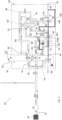
- FIGS. 10 schematic diagrams of a portion of an environment control system (ECS) 10 including an environmental control system pack 20, such as an air conditioning unit or pack for example, are depicted according to non-limiting embodiments.
- the environmental control system 10 is described with reference to an aircraft, alternative applications are also within the scope of the disclosure.
- the ECS 10 has an inlet 22 configured to receive a medium A from a source 24.
- the environmental control system pack 20 is configured to deliver a conditioned form of the medium A to an outlet 26 fluidly coupled to one or more loads, such as a cabin for example.
- the medium A may be bled air, which is pressurized air originating from i.e., being "bled" from, an engine or auxiliary power unit of the aircraft. It shall be understood that one or more of the temperature, humidity, and pressure of the bleed air provided via a bleed air system 24 can vary based upon the compressor stage and revolutions per minute of the engine or auxiliary power unit from which the air is drawn.
- the medium A provided to the inlet 22 may be fresh air, such as outside air for example.
- the outside air can be procured via one or more scooping mechanisms, such as an impact scoop or a flush scoop for example.
- the fresh air as described herein is at an ambient pressure equal to an air pressure outside of the aircraft when the aircraft is on the ground and is between an ambient pressure and a cabin pressure when the aircraft is in flight.
- the medium A may be provided from the cabin of the aircraft.
- the medium A is cabin discharge air, which is air leaving the cabin and that would typically be discharged overboard.
- the medium A is provided from a cabin air compressor located upstream from the inlet 22. It should be understood that a medium A including a mixture of any of the mediums described herein and/or other suitable mediums may be provided from another suitable source of the aircraft is also within the scope of the disclosure.
- the ECS pack 20 includes a RAM air circuit 30 having a shell or duct, illustrated schematically in broken lines at 32, within which one or more heat exchangers are located.
- the ram air shell 32 can receive and direct a medium, such as ram air for example, through a portion of the ECS pack 20.
- the one or more heat exchangers are devices built for efficient heat transfer from one medium to another. Although the heat exchangers are illustrated as having a single pass configuration, it should be appreciated that in other embodiments, at least one of the mediums may make multiple passes through the heat exchanger. Further, the mediums may be arranged in any suitable flow configuration at the heat exchanger, such as cross-flow, parallel flow, counter-flow, or any combination thereof. Examples of the type of heat exchangers that may be used, include, but are not limited to, double pipe, shell and tube, plate, plate and shell, adiabatic shell, plate fin, pillow plate, and fluid heat exchangers.
- the one or more heat exchangers arranged within the shell 32 may be referred to as a ram heat exchanger.
- the ram heat exchangers include a first or primary heat exchanger 34 and a second or secondary heat exchanger 36. Although two heat exchangers are illustrated, it should be understood that embodiments including a single heat exchanger, or alternatively, embodiments including more than two heat exchangers are also contemplated herein.
- ram air such as outside air for example, acts as a heat sink to cool the medium passing there through.
- the ECS pack 20 additionally comprises at least one thermodynamic device 40.
- the ECS pack 20 includes a single thermodynamic device 40; however, embodiments including additional thermodynamic devices are also within the scope of the disclosure.
- the thermodynamic device 40 is a mechanical device that includes components for performing thermodynamic work on a medium (e.g., extracts work from or applies work to the medium A by raising and/or lowering pressure and/or by raising and/or lowering temperature). Examples of a thermodynamic device 40 include an air cycle machine, a two-wheel air cycle machine, a three-wheel air cycle machine, a four-wheel air cycle machine, etc. In the illustrated, non-limiting embodiment, the thermodynamic device 40 is a four-wheel air cycle machine.
- the thermodynamic device 40 includes a compressor 42 and at least one turbine 44 operably coupled to each other via a shaft 46.
- the compressor 42 is a mechanical device that raises a pressure of a medium and can be driven by another mechanical device (e.g., a motor or a medium via a turbine). Examples of compressor types include centrifugal, diagonal or mixed-flow, axial-flow, reciprocating, ionic liquid piston, rotary screw, rotary vane, scroll, diaphragm, air bubble, etc.
- the turbine 44 is a mechanical device that expands a medium and extracts work therefrom (also referred to as extracting energy) to drive the compressor 42 via the shaft 46.
- the thermodynamic device 40 includes a first turbine 44a and a second turbine 44b.
- the thermodynamic device 40 includes a fan 48 mounted to the shaft 46.
- the fan 48 is a mechanical device that can force via push or pull methods a medium (e.g., ram air) through the shell 32 across the one or more ram heat exchangers 34, 36 and at a variable cooling flow rate to control temperatures.
- a medium e.g., ram air
- the first turbine 44a and the second turbine 44b are operable independently or in combination, to drive the compressor 42 and the fan 48 via the shaft 46.
- the fan 48 is illustrated as being part of the air cycle machine that forms the thermodynamic device 40, in other embodiments, the fan 48 may be separate from the thermodynamic device 40 and driven by another suitable means. In such instances, the fan 48 may be electrically driven, may be a tip-turbine fan, or may be part of a separate simple cycle machine.
- the ECS pack 20 may additionally include a dehumidification system.
- the dehumidification system includes a reheater 50, a condenser 52, and a water extractor or water collector 54 arranged in series relative to a flow of the medium A.
- the reheater 50 and condenser 52 are particular types of heat exchangers and the water collector 54 is a mechanical device that performs a process of removing water from a medium.
- the reheater 50 is illustrated as a separate heat exchanger located downstream from and arranged in fluid communication with an outlet of the secondary heat exchanger 36.
- the reheater 50, the condenser 52, and/or the water extractor 54 may form a high-pressure water separator because the pressure of the medium provided thereto is at or is very close to its highest pressure within the ECS pack 20.
- the functionality of the reheater 50 and the condenser 52 are integrated into a single heat exchanger. It should be understood that an ECS pack 20 having at least one dehumidification system with any suitable configuration is also contemplated herein.
- Valves e.g., flow regulation device or mass flow valve
- Valves are devices that regulate, direct, and/or control a flow of a medium by opening, closing, or partially obstructing various passageways within the tubes, pipes, etc. of the system. Valves can be operated by actuators, such that flow rates of the medium in any portion of the ECS pack 20 can be regulated to a desired value. It should be appreciated that the valves may be operated independently or in combination to form a medium A having a desired temperature and pressure at the outlet 26. For instance, a first valve V1 may be operable to control the supply of the medium A to the ECS pack 20.
- the ECS pack 20 may include at least one valve to allow the medium A to bypass at least one of the turbines 44.
- a second valve V2 may be arranged within a first turbine bypass conduit 60 extending parallel to the inlet of the first turbine 44a, such that when the second valve V2 is open, at least a portion of the medium A output from the secondary heat exchanger 36 bypasses the first turbine 44a.
- a third valve V3 may be arranged a within a second turbine bypass conduit 62 extending parallel to the inlet of the second turbine 44b, such that when the third valve V3 is open, at least a portion of the medium A output from the condenser 52 bypasses the second turbine 44b.
- a third or dehumidification bypass conduit 64 including a fourth valve V4 is arranged in parallel with an inlet of the dehumidification system, such as the reheater 50 for example, and is connected to a pass within the condenser 52, such that fluid within the third bypass conduit bypasses a first pass through the reheater, a first pass through the condenser, a second pass through the reheater, and the first turbine 44a.
- a fifth valve V5 may be operable to allow some or all of the flow output from the primary heat exchanger 34 to bypass the compressor 42.
- Each of the valves of the ECS pack 20 is operably coupled to a controller (not shown).
- the controller may be configured to adjust a position of the one or more valves based on a temperature and pressure of the medium A provided to the inlet 22 and the temperature and pressure demands of the one or more loads fluidly coupled to an outlet 26 of the ECS pack 20.
- the ECS pack 20 may be operable in at least one mode or operation, and in some embodiments in a plurality of modes of operation. Operation of the ECS pack 20 in a first mode may be associated with take-off, climb, or operation of the aircraft on the ground.
- valve V1 is opened such that the medium A, such as bleed air for example, is provided to the inlet 22 from the source 24 and valves V2, V3, and V4 may be closed.
- the medium A may be provided to the first or primary heat exchanger 34. Within the primary heat exchanger 34, the medium A is cooled via a flow of ram air, such as driven by the fan 48.
- At least one conduit 70 fluidly couples the outlet 72 of the primary heat exchanger 34 and the inlet 74 of the compressor 42. Accordingly, the cooled medium A flows from the primary heat exchanger 34 to the compressor 42 where the medium A is compressed to form compressed medium A'. The act of compressing the medium A heats the medium A and/or increases the pressure thereof.
- the outlet 76 of the compressor 42 is fluidly connected to an inlet 78 of the secondary heat exchanger 36 by at least one conduit 80.
- the compressed medium A' output from the compressor 42 is therefore provided to the secondary heat exchanger 36 where the compressed medium A' is again cooled via the flow of ram air.
- the compressed medium A' flows into conduit 84. Because valve V4 arranged within the dehumidification bypass conduit 64 fluidly connected to the conduit 84 is closed during normal operation, the cool compressed medium A' is configured to flow to the dehumidification system.
- the cool compressed medium A' is configured to flow through the reheater 50, the condenser 52, and the water extractor 54 sequentially.
- the cool compressed medium A' is cooled and further cooled within the reheater 50 and the condenser 52, respectively, causing any moisture within the compressed medium A' to condense. This moisture is then removed from the flow of compressed medium A' within the water extractor 54.
- the resulting cool, dry compressed medium A' output from the water extractor 54 is configured to pass through the reheater 50 again. Within this second pass through the reheater 50, the cool, dry compressed medium A' output from the water extractor 54 is at least partially heated by the compressed medium A' output from the secondary heat exchanger 36 of the ram air circuit 30 to produce a warm, dry compressed medium A'.
- valve V2 may be closed such that the dry compressed medium A' output from the reheater 50 is provided from the dehumidification system to an inlet 86 of the first turbine 44a via a passage 88.
- work is extracted from the compressed medium A' and is used to drive the compressor 42 and the fan 48.
- the outlet 90 of the first turbine 44a is arranged in fluid communication with the condenser 52 via a conduit 92. Accordingly, the cooled expanded medium A" output from the first turbine outlet 90 flows through passage 92 back to the condenser 52 where the expanded medium A" is heated.
- valve V3 is closed, the heated expanded medium A" output from the condenser 52 is provided to the inlet 94 of the second turbine 44b.
- the medium A may be configured to bypass one of the plurality of turbines of the thermodynamic device 40.
- the valves are positioned such that the medium A bypasses the first turbine 44a.
- Such a mode of operation may be substantially identical to the first mode; however, valve V2 is open such that all of the compressed medium A' is provided to the first turbine bypass conduit 60.
- the flow of the compressed medium A' downstream from the first turbine bypass conduit 60 may also be the same as in the first mode.
- the valve V4 arranged within the dehumidification bypass conduit 64 may be open. Accordingly, the entire flow of compressed medium A' within conduit 84 may bypass the dehumidification system and the first turbine 44a and flow directly into the dehumidification bypass conduit 64. In such embodiments, the compressed medium A' will flow through the second pass of the condenser 52. However, because no secondary flow is provided to the condenser 52, the temperature of the compressed medium A' will remain substantially constant. From the condenser 52, the compressed medium A' may be provided to the second turbine 44b, within which the compressed medium A' is expanded to form an expanded medium A".
- the flow of medium A typically bypasses the first turbine 44a and is provided to the second turbine 44b.
- the ECS pack 20 may be adapted such that the medium A is alternatively or additionally able to flow through only the first turbine 44a and bypass the second turbine 44b.
- the controller C may selectively operate the ECS 10 in the second mode or the third mode or supply the medium to the second turbine or to the first turbine based on the demand of one or more loads connected to the environmental control system pack 20 and/or a flow requirement of the environmental control system pack 20.
- the ECS pack 20 includes another bypass conduit 100, also referred to herein as a system bypass conduit, operable to bypass the second pass of the condenser 52 and the second turbine 44b.
- the system bypass conduit 100 delivers the expanded medium A' output from the outlet 90 of the first turbine 44a to a location at or directly upstream from the outlet 26 associated with one or more loads.
- a sixth valve V6 may be fluidly coupled to the fourth bypass conduit 100 and operable to control a flow of medium therethrough. Although the valve V6 is generally illustrated as being located near an outlet of the system bypass conduit 100, it should be understood that the valve V6 may be located at any suitable location to control the flow.
- an inlet 102 of the system bypass conduit 100 is located directly downstream from the outlet 90 of the first turbine 44a.
- the inlet 102 may be positioned upstream from the interface between the first turbine bypass conduit 60 and the outlet of the first turbine 44a relative to the flow of medium A.
- a valve V7 such as a check valve for example, may be located at or directly downstream from the inlet end 102 of the fourth bypass conduit within conduit 92 to prevent undesired flow of any of compressed medium A' from the bypass conduit 60 or any flow from the condenser 52 backwards into the system bypass conduit 100.
- the inlet 102 of the system bypass conduit 100 may be located downstream from interface between the first turbine bypass conduit 60 and the outlet of the first turbine 44a relative to the flow of medium A.
- both the expanded medium A' output from the turbine 44a and any compressed medium A' within the first turbine bypass conduit 60 are provided directly to the outlet 26.
- the valve V7 may be located at or directly downstream from the inlet end 102 of the system bypass conduit 100 within conduit 92 to prevent undesired flow of a medium from the condenser 52 into the lower pressure system bypass conduit 100.
- valve V6 arranged within the system bypass conduit 100 is open.
- the flow of the medium A between the inlet 22 and the inlet 86 of the turbine 44a may be substantially identical to that described with respect to the first and second modes.
- the compressed medium A' is expanded within the first turbine 44a, thereby creating an expanded medium A".
- the expanded medium A" is provided to the system bypass conduit 100 and to the outlet 26.
- valve V2 is closed during operation in the third mode.
- valve V2 may be open during operation of the ECS pack 20 in the third mode.
- the medium A can be provided to the first turbine 44a and the second turbine 44b of the ECS pack 20 in parallel.
- valves V1, V2, and V6 are open and valves V3 and V4 are closed.
- the medium A is provided from the source 22 to the first or primary heat exchanger 34 where the medium A is cooled, such as via a flow of ram air. From the outlet 72 of the primary heat exchanger 34, the cooled medium A flows to the compressor 42 where the medium A is compressed to form compressed medium A'. From the compressor 42, the compressed medium A' is provided to the secondary heat exchanger 36 where the compressed medium A' is again cooled via the flow of ram air. From the outlet of the 82 of the secondary heat exchanger 36, the compressed medium A' is provided to the reheater 50 via conduit 84.
- the cool compressed medium A' is configured to flow through the reheater 50, the condenser 52, and the water extractor 54 sequentially, as previously described.
- a first portion of the resulting, warm, dry compressed medium A' output from the reheater 50 is provided to the inlet 86 of the first turbine 44a and a second portion of the compressed medium A' output from the reheater 50 is provided to the first turbine bypass conduit 60.
- energy is extracted from the first portion of the compressed medium A' to form an expanded medium A".
- the expanded medium A" is delivered to the outlet 26 via the system bypass conduit 100.
- the second portion of the compressed medium A' flows through passage 92 back to the condenser 52 where the second portion of the compressed medium A' is heated.
- the heated second portion of the compressed medium A'output from the condenser 52 is provided to the inlet 94 of the second turbine 44b such that energy is extracted from the second portion of the compressed medium A' to form an expanded medium A".
- the expanded medium A" provided at the outlet 96 of the second turbine 44b may be delivered to the outlet 26 independently or may be mixed with the expanded medium A" from the system bypass conduit 100 upstream from the outlet 26.
- valves V1, V4, and V6 are open and valve V3 is closed.
- the medium A is provided from the source 22 to the first or primary heat exchanger 34 where the medium A is cooled, such as via a flow of ram air.
- the cooled medium A flows to the compressor 42 where the medium A is compressed to form compressed medium A'.
- the compressed medium A' is provided to the secondary heat exchanger 36 where the compressed medium A' is again cooled via the flow of ram air.
- the compressed medium A' flows into conduit 84.
- a first portion of compressed medium A' within the conduit 84 is configured to flow toward the dehumidification system and a second portion of compressed medium A' within the conduit 84 is provided to the dehumidification bypass conduit 64.
- the first portion of the compressed medium A' flows through the reheater 50, the condenser 52, and the water extractor 54 sequentially, as previously described.
- the resulting, warm, dry compressed medium A' output from the reheater 50 may be provided to the inlet 86 of the first turbine 44a.
- energy is extracted from the first portion of the compressed medium A' to form an expanded medium A".
- a portion of the compressed medium A' is also provided to the first turbine bypass conduit 60.
- the expanded medium A" output from the outlet 90 of the first turbine 44a, and in some embodiments, the compressed medium A' from the first turbine bypass conduit 60 are then provided to the outlet l26 via the system bypass conduit 100.
- the compressed medium A' is provided to the second pass of the condenser 52.
- the second portion of the compressed medium A' is heated by the flow of the first portion of the compressed medium A'.
- the warm compressed medium A' is provided to the second turbine 44b to form an expanded medium A".
- the expanded medium A" provided at the outlet 96 of the second turbine 44b may be delivered to the outlet 26 independently or may be mixed with the expanded medium A" from the system bypass conduit 100 upstream from the outlet 26.
- valve V5 may be opened such that at least a portion of the medium A bypasses the compressor 42.
- a compressor and ram heat exchanger bypass conduit 110 may fluidly couple a location upstream of both the compressor 42 and the compressor bypass containing valve V5 to a location directly upstream from the inlet 86 of the first turbine 44a and the first turbine bypass conduit 60.
- a valve such as a check valve V8 for example, may be arranged within the compressor and ram heat exchanger bypass conduit 110.
- medium A may bypass the compressor 42 and secondary heat exchanger 36 to prevent the occurrence of a large pressure drops at the heat exchanger 36.
- the compressor and ram heat exchanger bypass conduit 110 is illustrated in combination with a system bypass conduit located downstream form the first turbine bypass conduit 60, it should be appreciated that the system of FIG. 1 , as well as any other suitable system may be adapted to include a compressor and ram heat exchanger bypass conduit 110 as disclosed herein.
- any environmental control system having a primary and secondary heat exchanger 34, 36 may be adapted to include at least the first bypass conduit and a corresponding valve, to selectively provide the flow of a medium A to the primary and secondary heat exchangers 34, 36 in series and in parallel.
Landscapes
- Engineering & Computer Science (AREA)
- Physics & Mathematics (AREA)
- Mechanical Engineering (AREA)
- Thermal Sciences (AREA)
- General Engineering & Computer Science (AREA)
- Health & Medical Sciences (AREA)
- General Health & Medical Sciences (AREA)
- Pulmonology (AREA)
- Aviation & Aerospace Engineering (AREA)
- Control Of Turbines (AREA)
Applications Claiming Priority (1)
| Application Number | Priority Date | Filing Date | Title |
|---|---|---|---|
| US18/356,399 US20250026479A1 (en) | 2023-07-21 | 2023-07-21 | Environmental control system with adaptive turbine arrangement |
Publications (1)
| Publication Number | Publication Date |
|---|---|
| EP4495005A1 true EP4495005A1 (fr) | 2025-01-22 |
Family
ID=91961958
Family Applications (1)
| Application Number | Title | Priority Date | Filing Date |
|---|---|---|---|
| EP24190160.2A Pending EP4495005A1 (fr) | 2023-07-21 | 2024-07-22 | Système de contrôle environnemental avec agencement de turbine adaptatif |
Country Status (2)
| Country | Link |
|---|---|
| US (1) | US20250026479A1 (fr) |
| EP (1) | EP4495005A1 (fr) |
Citations (5)
| Publication number | Priority date | Publication date | Assignee | Title |
|---|---|---|---|---|
| US20210188449A1 (en) * | 2019-12-19 | 2021-06-24 | Hamilton Sundstrand Corporation | Air cycle machines, air cycle machine systems, and methods of controlling air flow in air cycle machines |
| EP4036013A2 (fr) * | 2021-01-29 | 2022-08-03 | Hamilton Sundstrand Corporation | Architecture d'air ambiant avec un seul acm sans turbine d'ambiance |
| US20220340287A1 (en) * | 2021-04-27 | 2022-10-27 | The Boeing Company | Aircraft environmental control systems having electrically powered ram circuit fans |
| EP4082911A1 (fr) * | 2021-04-29 | 2022-11-02 | Hamilton Sundstrand Corporation | Système de climatisation à 100 % air ambiant avec turbines à prélèvement d'air moteur agencées en série |
| EP4331991A1 (fr) * | 2022-08-29 | 2024-03-06 | Hamilton Sundstrand Corporation | Système de contrôle environnemental à faible pression d'entrée |
Family Cites Families (1)
| Publication number | Priority date | Publication date | Assignee | Title |
|---|---|---|---|---|
| US10745136B2 (en) * | 2013-08-29 | 2020-08-18 | Hamilton Sunstrand Corporation | Environmental control system including a compressing device |
-
2023
- 2023-07-21 US US18/356,399 patent/US20250026479A1/en active Pending
-
2024
- 2024-07-22 EP EP24190160.2A patent/EP4495005A1/fr active Pending
Patent Citations (5)
| Publication number | Priority date | Publication date | Assignee | Title |
|---|---|---|---|---|
| US20210188449A1 (en) * | 2019-12-19 | 2021-06-24 | Hamilton Sundstrand Corporation | Air cycle machines, air cycle machine systems, and methods of controlling air flow in air cycle machines |
| EP4036013A2 (fr) * | 2021-01-29 | 2022-08-03 | Hamilton Sundstrand Corporation | Architecture d'air ambiant avec un seul acm sans turbine d'ambiance |
| US20220340287A1 (en) * | 2021-04-27 | 2022-10-27 | The Boeing Company | Aircraft environmental control systems having electrically powered ram circuit fans |
| EP4082911A1 (fr) * | 2021-04-29 | 2022-11-02 | Hamilton Sundstrand Corporation | Système de climatisation à 100 % air ambiant avec turbines à prélèvement d'air moteur agencées en série |
| EP4331991A1 (fr) * | 2022-08-29 | 2024-03-06 | Hamilton Sundstrand Corporation | Système de contrôle environnemental à faible pression d'entrée |
Also Published As
| Publication number | Publication date |
|---|---|
| US20250026479A1 (en) | 2025-01-23 |
Similar Documents
| Publication | Publication Date | Title |
|---|---|---|
| EP3945030B1 (fr) | Système de réglage environnemental d'un aéronef | |
| EP3489142B1 (fr) | Système de commande environnemental d'aéronef avec des turbines à air de prélèvement en série | |
| US11939065B2 (en) | Aircraft environmental control system | |
| EP3514065A1 (fr) | Système de contrôle environnemental d'un aéronef | |
| US12097962B2 (en) | Aircraft environmental control system | |
| EP4082911B1 (fr) | Système de climatisation à 100 % air ambiant avec turbines à prélèvement d'air moteur agencées en série | |
| EP4036013A2 (fr) | Architecture d'air ambiant avec un seul acm sans turbine d'ambiance | |
| EP4005925A1 (fr) | Architecture d'air ambiant avec machine à cycle d'air unique et séparateur d'eau haute pression | |
| EP4331991A1 (fr) | Système de contrôle environnemental à faible pression d'entrée | |
| EP4273044A1 (fr) | 100% système de régulation environnementale d'air ambiant | |
| EP4495005A1 (fr) | Système de contrôle environnemental avec agencement de turbine adaptatif | |
| EP4520664A1 (fr) | Système de contrôle environnemental moins de saignement | |
| US12234018B2 (en) | Environmental control system with no bleed driven throttle | |
| US20260028127A1 (en) | Bleed air powered ambient aircraft environmental control system |
Legal Events
| Date | Code | Title | Description |
|---|---|---|---|
| PUAI | Public reference made under article 153(3) epc to a published international application that has entered the european phase |
Free format text: ORIGINAL CODE: 0009012 |
|
| STAA | Information on the status of an ep patent application or granted ep patent |
Free format text: STATUS: THE APPLICATION HAS BEEN PUBLISHED |
|
| AK | Designated contracting states |
Kind code of ref document: A1 Designated state(s): AL AT BE BG CH CY CZ DE DK EE ES FI FR GB GR HR HU IE IS IT LI LT LU LV MC ME MK MT NL NO PL PT RO RS SE SI SK SM TR |
|
| STAA | Information on the status of an ep patent application or granted ep patent |
Free format text: STATUS: REQUEST FOR EXAMINATION WAS MADE |
|
| 17P | Request for examination filed |
Effective date: 20250722 |
|
| GRAP | Despatch of communication of intention to grant a patent |
Free format text: ORIGINAL CODE: EPIDOSNIGR1 |
|
| STAA | Information on the status of an ep patent application or granted ep patent |
Free format text: STATUS: GRANT OF PATENT IS INTENDED |
|
| INTG | Intention to grant announced |
Effective date: 20260304 |