EP4495031A1 - Renforcement pour réduire le bruit et améliorer la résistance à la flexion pour rouleaux métalliques - Google Patents
Renforcement pour réduire le bruit et améliorer la résistance à la flexion pour rouleaux métalliques Download PDFInfo
- Publication number
- EP4495031A1 EP4495031A1 EP24181520.8A EP24181520A EP4495031A1 EP 4495031 A1 EP4495031 A1 EP 4495031A1 EP 24181520 A EP24181520 A EP 24181520A EP 4495031 A1 EP4495031 A1 EP 4495031A1
- Authority
- EP
- European Patent Office
- Prior art keywords
- bearing
- roller
- reinforcement
- examples
- metal tube
- Prior art date
- Legal status (The legal status is an assumption and is not a legal conclusion. Google has not performed a legal analysis and makes no representation as to the accuracy of the status listed.)
- Pending
Links
- 230000002787 reinforcement Effects 0.000 title claims abstract description 111
- 239000002184 metal Substances 0.000 title claims abstract description 82
- 229910052751 metal Inorganic materials 0.000 title claims abstract description 82
- 239000007769 metal material Substances 0.000 claims abstract description 7
- 229910052755 nonmetal Inorganic materials 0.000 claims abstract description 5
- 239000010410 layer Substances 0.000 claims description 15
- 229920000114 Corrugated plastic Polymers 0.000 claims description 14
- 239000002335 surface treatment layer Substances 0.000 claims description 10
- 229920001296 polysiloxane Polymers 0.000 claims description 6
- 239000000843 powder Substances 0.000 claims description 6
- 239000000463 material Substances 0.000 description 23
- 229920003023 plastic Polymers 0.000 description 11
- 239000004033 plastic Substances 0.000 description 11
- -1 polyoxymethylene Polymers 0.000 description 9
- 239000004743 Polypropylene Substances 0.000 description 6
- 229920001155 polypropylene Polymers 0.000 description 6
- CWYNVVGOOAEACU-UHFFFAOYSA-N Fe2+ Chemical compound [Fe+2] CWYNVVGOOAEACU-UHFFFAOYSA-N 0.000 description 5
- 229920000642 polymer Polymers 0.000 description 5
- 239000002210 silicon-based material Substances 0.000 description 5
- 239000010935 stainless steel Substances 0.000 description 5
- 229910001220 stainless steel Inorganic materials 0.000 description 5
- 238000003466 welding Methods 0.000 description 5
- 238000005516 engineering process Methods 0.000 description 4
- VYZAMTAEIAYCRO-UHFFFAOYSA-N Chromium Chemical compound [Cr] VYZAMTAEIAYCRO-UHFFFAOYSA-N 0.000 description 3
- 239000004677 Nylon Substances 0.000 description 3
- 229930040373 Paraformaldehyde Natural products 0.000 description 3
- 230000008878 coupling Effects 0.000 description 3
- 238000010168 coupling process Methods 0.000 description 3
- 238000005859 coupling reaction Methods 0.000 description 3
- 229920001778 nylon Polymers 0.000 description 3
- 229920006324 polyoxymethylene Polymers 0.000 description 3
- 239000000654 additive Substances 0.000 description 2
- 239000000853 adhesive Substances 0.000 description 2
- 230000001070 adhesive effect Effects 0.000 description 2
- 239000002131 composite material Substances 0.000 description 2
- 230000007812 deficiency Effects 0.000 description 2
- 239000003365 glass fiber Substances 0.000 description 2
- 239000007787 solid Substances 0.000 description 2
- 239000002023 wood Substances 0.000 description 2
- 229910000975 Carbon steel Inorganic materials 0.000 description 1
- 238000007792 addition Methods 0.000 description 1
- 239000010962 carbon steel Substances 0.000 description 1
- 238000000748 compression moulding Methods 0.000 description 1
- 230000003247 decreasing effect Effects 0.000 description 1
- 239000011152 fibreglass Substances 0.000 description 1
- 229910052500 inorganic mineral Inorganic materials 0.000 description 1
- 150000002739 metals Chemical class 0.000 description 1
- 239000011707 mineral Substances 0.000 description 1
- 238000012986 modification Methods 0.000 description 1
- 230000004048 modification Effects 0.000 description 1
- 239000002861 polymer material Substances 0.000 description 1
- 238000003856 thermoforming Methods 0.000 description 1
Images





Classifications
-
- B—PERFORMING OPERATIONS; TRANSPORTING
- B65—CONVEYING; PACKING; STORING; HANDLING THIN OR FILAMENTARY MATERIAL
- B65G—TRANSPORT OR STORAGE DEVICES, e.g. CONVEYORS FOR LOADING OR TIPPING, SHOP CONVEYOR SYSTEMS OR PNEUMATIC TUBE CONVEYORS
- B65G39/00—Rollers, e.g. drive rollers, or arrangements thereof incorporated in roller-ways or other types of mechanical conveyors
- B65G39/02—Adaptations of individual rollers and supports therefor
-
- B—PERFORMING OPERATIONS; TRANSPORTING
- B65—CONVEYING; PACKING; STORING; HANDLING THIN OR FILAMENTARY MATERIAL
- B65G—TRANSPORT OR STORAGE DEVICES, e.g. CONVEYORS FOR LOADING OR TIPPING, SHOP CONVEYOR SYSTEMS OR PNEUMATIC TUBE CONVEYORS
- B65G23/00—Driving gear for endless conveyors; Belt- or chain-tensioning arrangements
- B65G23/02—Belt- or chain-engaging elements
- B65G23/04—Drums, rollers, or wheels
- B65G23/08—Drums, rollers, or wheels with self-contained driving mechanisms, e.g. motors and associated gearing
-
- F—MECHANICAL ENGINEERING; LIGHTING; HEATING; WEAPONS; BLASTING
- F16—ENGINEERING ELEMENTS AND UNITS; GENERAL MEASURES FOR PRODUCING AND MAINTAINING EFFECTIVE FUNCTIONING OF MACHINES OR INSTALLATIONS; THERMAL INSULATION IN GENERAL
- F16C—SHAFTS; FLEXIBLE SHAFTS; ELEMENTS OR CRANKSHAFT MECHANISMS; ROTARY BODIES OTHER THAN GEARING ELEMENTS; BEARINGS
- F16C13/00—Rolls, drums, discs, or the like; Bearings or mountings therefor
-
- B—PERFORMING OPERATIONS; TRANSPORTING
- B65—CONVEYING; PACKING; STORING; HANDLING THIN OR FILAMENTARY MATERIAL
- B65G—TRANSPORT OR STORAGE DEVICES, e.g. CONVEYORS FOR LOADING OR TIPPING, SHOP CONVEYOR SYSTEMS OR PNEUMATIC TUBE CONVEYORS
- B65G13/00—Roller-ways
- B65G13/02—Roller-ways having driven rollers
-
- F—MECHANICAL ENGINEERING; LIGHTING; HEATING; WEAPONS; BLASTING
- F16—ENGINEERING ELEMENTS AND UNITS; GENERAL MEASURES FOR PRODUCING AND MAINTAINING EFFECTIVE FUNCTIONING OF MACHINES OR INSTALLATIONS; THERMAL INSULATION IN GENERAL
- F16C—SHAFTS; FLEXIBLE SHAFTS; ELEMENTS OR CRANKSHAFT MECHANISMS; ROTARY BODIES OTHER THAN GEARING ELEMENTS; BEARINGS
- F16C13/00—Rolls, drums, discs, or the like; Bearings or mountings therefor
- F16C13/02—Bearings
Definitions
- the present application relates generally, in some examples, to a roller. More specifically, the present application relates, in some examples, to a reinforced metal roller.
- Metal rollers are sometimes used in conveyors.
- one or more metal rollers may be used to transport an object.
- the inventors have identified numerous deficiencies and problems with the existing technologies in this field.
- existing technologies may result in excessively loud noise during transportation.
- existing technologies are a heavy and result in increased weight of a roller system.
- a roller in an example embodiment, includes a metal tube extending between a first end and a second end, where the metal tube includes an outer surface and an inner surface.
- the example roller includes a first bearing disposed at the first end.
- the example roller includes a second bearing disposed at the second end.
- the example roller includes a reinforcement filling in contact with the inner surface of the metal tube, where the reinforcement filling is made at least partially of a non-metal material.
- the reinforcement filling fills a space inside the metal tube and between the first bearing and the second bearing.
- a roller of an example embodiment further includes a shaft extending through the metal tube and between the first bearing and the second bearing.
- the reinforcement filling fills a space inside the metal tube, outside the shaft, and between the first bearing and the second bearing.
- the reinforcement filling includes a corrugated plastic filling.
- the corrugated plastic filling includes at least one of a honeycomb reinforcement structure, a bubble reinforcement structure, a rectangular reinforcement structure, or a plate reinforcement structure.
- the corrugated plastic filling includes a plurality of corrugated sheets.
- each of the plurality of corrugated sheets are stacked in a direction extending between the first bearing and the second bearing.
- each of the plurality of corrugated sheets defines a circular shape.
- each of the plurality of corrugated sheets is disposed between two reinforcement layers.
- each of the plurality of corrugated sheets is further disposed between two surface treatment layers.
- the plurality of corrugates sheets are fused together.
- the reinforcement filling includes a silicone-based powder.
- the roller of an example embodiment further includes a motor positioned inside the metal tube.
- the reinforcement filling fills a space inside the metal tube, outside the motor, and between the first bearing and the second bearing.
- the metal tube includes 20gauge metal.
- At least one of the first bearing or the second bearing includes a hex shaft.
- a roller conveyor system in an example embodiment, includes one or more conveyor frames.
- the example roller conveyor system includes one or more conveyor legs.
- the example roller conveyor system includes one or more example rollers.
- Each of the example rollers includes a metal tube extending between a first end and a second end, where the metal tube includes an outer surface and an inner surface.
- Each of the example rollers includes a first bearing disposed at the first end.
- Each of the example rollers includes a second bearing disposed at the second end.
- Each of the example rollers includes a reinforcement filling in contact with the inner surface of the metal tube, where the reinforcement filling is made at least partially of a non-metal material.
- the reinforcement filling fills a space inside the metal tube and between the first bearing and the second bearing.
- Each of the rollers of an example embodiment further includes a shaft extending through the metal tube and between the first bearing and the second bearing.
- the reinforcement filling fills a space inside the metal tube, outside the shaft, and between the first bearing and the second bearing.
- the reinforcement filling includes a corrugated plastic filling.
- the corrugated plastic filling includes at least one of a honeycomb reinforcement structure, a bubble reinforcement structure, a rectangular reinforcement structure, or a plate reinforcement structure.
- the corrugated plastic filling includes a plurality of corrugated sheets.
- each of the plurality of corrugated sheets are stacked in a direction extending between the first bearing and the second bearing.
- each of the plurality of corrugated sheets defines a circular shape.
- each of the plurality of corrugated sheets is disposed between two reinforcement layers.
- each of the plurality of corrugated sheets is further disposed between two surface treatment layers.
- the plurality of corrugates sheets are fused together.
- the reinforcement filling includes a silicone-based powder.
- Each of the plurality of rollers of an example embodiment further includes a motor positioned inside the metal tube.
- the reinforcement filling fills a space inside the metal tube, outside the motor, and between the first bearing and the second bearing.
- the metal tube includes 20gauge metal.
- At least one of the first bearing or the second bearing includes at least one of a hex shaft or a circular shaft.
- exemplary means serving as an example, instance, or illustration. Any aspect or design described herein as "exemplary” is not necessarily to be construed as preferred or advantageous over other aspects or designs. Rather, use of the word exemplary is intended to present concepts in a concrete fashion.
- a particular feature may be disclosed with respect to only one of several implementations, such feature may be combined with one or more other features of the other implementations as may be desired and advantageous for any given or particular application.
- the terms “includes” and “including” and variants thereof are used in either the detailed description or the claims, these terms are intended to be inclusive in a manner similar to the term “comprising.”
- the term "or” is intended to mean an inclusive “or” rather than an exclusive “or”. That is, unless specified otherwise, or clear from context, "X employs A or B” is intended to mean any of the natural inclusive permutations. That is, if X employs A; X employs B; or X employs both A and B, then "X employs A or B” is satisfied under any of the foregoing instances.
- the articles “a” and “an” as used in this application and the appended claims should generally be construed to mean “one or more” unless specified otherwise or clear from context to be directed to a singular form.
- Coupled refers to both direct coupling, fixing, or attaching, as well as indirect coupling, fixing, or attaching through one or more intermediate components or features, unless otherwise specified herein.
- coupling can be accomplished through welding one component to another component.
- the term "positioned directly on” refers to a first component being positioned on a second component such that they make contact.
- the term “positioned directly between” refers to a first component being positioned between a second component and a third component such that the first component makes contact with both the second component and the third component.
- a first component that is "positioned between" a second component and a third component may or may not have contact with the second component and the third component.
- a first component that is "positioned between" a second component and a third component is positioned such that there may be other intervening components between the second component and the third component other than the first component.
- rollers it is desirable, in some examples, for rollers to be lightweight and produce a low amount of noise while in use.
- Embodiments of the present disclosure include, but are not limited to, a reinforced metal roller that is lightweight and does not create excessive noise.
- example reinforced metal rollers may produce 10% to 20% less noise than existing technologies.
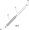
- an example roller 100 is provided.
- the example roller 100 has a cylindrical shape.
- the example roller 100 may extend between a first end and a second end.
- a roller 100 has a metal tube 110 having a cylindrical shape.
- metal tube 110 may extend between the first end and the second end.
- metal tube 110 has a diameter equal to the diameter of the roller 100.
- metal tube 110 has a hollow cylindrical shape.
- metal tube 110 is made of, for example, ferrous or nonferrous metals.
- metal tube 110 may be made of stainless steel.
- metal tube 110 has an outer surface and an inner surface. In some examples, metal tube 110 has a low thickness between the outer surface and the inner surface. For example, metal tube 110 may have a thickness less than 16 gauge, in some examples, a thickness of 20 gauge in other examples, and a thickness of 3mm in yet other examples. The low thickness of metal tube 110 provides example benefits including decreased weight and cost.
- the example roller 100 is able to bear weight with a lower thickness due, for example, a reinforcement filling such as a corrugated plastic material or a silicone-based powder.
- a roller has a first bearing 120 disposed at the first end of roller 100.
- first bearing 120 has a circular shape.
- first bearing 120 may have a circular shape and have a diameter equal to the diameter of roller 100 and/or outer layer 110.
- first bearing 120 is made of a hard material.
- first bearing 120 may be made of ferrous metal, chrome steal, stainless steel, polymer plastic (e.g., nylon, polyoxymethylene, etc.), a hybrid material, and/or the like
- first bearing 120 is coupled to the first end of roller 100.
- first bearing 120 may be coupled to outer layer 110 of roller 100 and/or materials inside of outer layer 110.
- first bearing 120 may be coupled to a corrugated plastic filling inside roller 100.
- first bearing 120 may be coupled to a motor placed inside of roller 100.
- first bearing 120 is fused to roller 100 via ultrasonic welding, friction welding, press fitting, and/or the like.
- first bearing 120 includes a shaft 125.
- shaft 125 extends away from roller 100.
- shaft 125 is a hex shaft, and in other examples, shaft 125 may be circular, rectangular, and/or the like.
- shaft 125 is made of the same material as the rest of first bearing 120.
- shaft 125 may be made of ferrous metal, chrome steal, stainless steel, polymer plastic (e.g., nylon, polyoxymethylene, etc.), a hybrid material, and/or the like
- a roller has a second bearing 130 disposed at the second end of roller 100.
- second bearing 130 has a circular shape.
- second bearing 130 may be a circular shape and have a diameter equal to the diameter of roller 100 and/or outer layer 110.
- second bearing 130 is made of a hard material.
- second bearing 130 may be made of ferrous material, chrome steal, stainless steel, polymer plastic (e.g., nylon, polyoxymethylene, etc.), a hybrid material, and/or the like.
- second bearing 130 is coupled to the second end of roller 100.
- second bearing 130 may be coupled to outer layer 110 of roller 100 and/or materials inside of outer layer 110.
- second bearing 130 may be coupled to a corrugated plastic filling inside roller 100, in other examples, second bearing 130 may be coupled to a motor placed inside of roller 100.
- second bearing 130 is fused to roller 100 via ultrasonic welding, friction welding, press fitting, and/or the like.
- second bearing 130 includes a shaft 135.
- shaft 135 extends away from roller 100.
- shaft 135 is a hex shaft, and in other examples, shaft 135 may circular, rectangular, and/or the like.
- shaft 135 is made of the same material as the rest of second bearing 130.
- shaft 135 is made of metal.
- roller 100 includes reinforcement filling 210.
- reinforcement filling 210 consists of a plurality of corrugated sheets 220.
- reinforcement filling 210 is in contact with the inner surface of metal tube 110.
- reinforcement filling 210 is made at least partially of a non-metal material.
- reinforcement filling 210 may be made of a polymer material, wood, a rubber material, wood and polymer composite material, or other composite materials that would provide reinforcement to roller 100.
- reinforcement filling 210 includes additives.
- reinforcement filling 210 is a corrugated plastic filling such as polypropylene or other similar materials.
- reinforcement filling 210 may be made of a lightweight plastic or silicone-based material that provides reinforcement to roller 210.
- reinforcement filling 210 is lighter in weight than metal materials.
- reinforcement filling 210 increases the flexural strength by 50% to 100% compared to non-reinforced rollers.
- reinforcement filling 210 dampens noise produced by roller 100 by 10% to 20%.
- reinforcement filling 210 is shaped into alternating ridges and/or grooves.
- reinforcement filling 210 is textured.
- reinforcement filling 210 may include a honeycomb structure, a bubble structure, a series of rectangular grooves, a series of plate-shaped grooves, and/or the like.
- metal tube 110 is configured house the plurality of corrugated sheets 220.
- the plurality of corrugated sheets 220 may be pushed into the metal tube 110.
- the plurality of corrugated sheets 220 are stacked such that a space inside the metal tube 110 and between the first bearing 120 and the second bearing 130 is filled.
- corrugated sheets 220 may be stacked in a direction extending between first bearing 120 and second bearing 130.
- corrugated sheets 220 are stacked in a direction perpendicular to a direction between first bearing 120 and second bearing 130.
- each of corrugated sheets 220 may extend fully between first bearing 120 and second bearing 130 and be stacked to fill the metal tube 110. In other examples, corrugated sheets 220 do not extend fully between first bearing 120 and second bearing 130.
- corrugated sheets 220 may be stacked both in the direction between first bearing 120 and second bearing 130 and perpendicularly to the direction between first bearing 120 and second bearing 130.
- corrugated sheets 220 may be stacked such that a space a space inside the metal tube 110 and between the first bearing 120 and the second bearing 130 is filled.
- one or more of the plurality of corrugated sheets 220 may define a circular shape. Additionally or alternatively, one or more of the plurality of corrugated sheets 220 may be square, rectangular, oval, triangular, hexagonal, and/or the like. In some examples, the plurality of corrugated sheets 220 may comprise a plurality of uniform or different shapes.
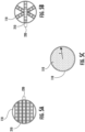
- FIG. 2B a front view of a plurality of corrugated sheets 220 is provided in accordance with example embodiments of the present disclosure.
- the plurality of corrugated sheets 220 are fused together.
- the plurality of corrugated sheets 220 may be fused together by an adhesive, by stacking under heat and pressure, and/or the like.
- the plurality of corrugated sheets 220 are fused together and then pushed into the metal tube 110.
- the plurality of corrugated sheets 220 are each made of a corrugated plastic material (e.g., polypropylene).
- each of corrugated sheets 220 may have a honeycomb, bubble, rectangular, plate, and/or the like structure.
- each of corrugated sheets 220 shares the same structure, and in other examples, the plurality of corrugated sheets 220 include corrugated sheets with varied structures.
- the plurality of corrugated sheets 220 may provide reinforcement when an example roller 100 is bearing weight.
- the individual corrugated sheet 220 may be any of the plurality of corrugates sheets 220 depicted in FIGS. 2A-2B .
- each of the plurality of corrugated sheets 220 is disposed between a two reinforcement layers 230.
- the reinforcement layers 230 each cover a side of corrugated sheet 220.
- the reinforcement layers 230 are made of fiberglass or other plastic materials that provide strength and structural integrity to corrugated sheet 220.
- each of the plurality of corrugated sheets 220 and the surrounding reinforcement layers 230 are disposed between two surface treatment layers 240.
- surface treatment layers 240 may be fused to the corrugated sheet 220 and/or reinforcement layers 230 through thermal fusing, thermoforming, compression molding, and/or the like.
- surface treatment layers 240 are configured to increase the strength of corrugated sheet 220.
- surface treatment layers 240 are configured to be fused to a surface treatment layer of a different corrugated sheet.
- surface treatment layers 240 may be made of a polymer (e.g., plastic) material.
- surface treatment layers 240 may include additives such as glass fiber, minerals, chopped strand glass fiber, and/or the like.
- the roller 100 includes a plurality of layers positioned in between first bearing 120 and second bearing 130.
- the reinforcement filling 210 is placed within a metal tube 110.
- reinforcement filling 210 may be in contact with the inner surface of the metal tube 110.
- reinforcement filling 210 and metal tube 110 extend between first bearing 120 and second bearing 130.
- FIG. 4A a front cross-sectional view of a roller 100 is provided when the roller 100 includes a shaft 400.
- the reinforcement filling 210 fills a space inside the metal tube 110, outside the shaft 400, and between the first bearing 120 and the second bearing 130.
- the shaft 400 extends through the metal tube 110 and between the first bearing 120 and the second bearing 130.
- the shaft 400 may extend through a center of the metal tube 110.
- the shaft 400 is in contact with the reinforcement filling 210.
- the shaft 400 is coupled to the first bearing 120 and/or the second bearing 130.
- the shaft is an extension of shaft 125 and/or shaft 135.
- shaft 400 is a cylindrical shape. In other examples, shaft 400 may be a hexagonal shape, rectangular shape, and/or the like. In some examples, shaft 400 is hollow, and in other examples, shaft 400 may be solid throughout.
- shaft 400 is made of a metal material.
- shaft 400 may be made of an identical material to first bearing 120 and/or second bearing 130.
- shaft 400 may be made of an identical material to shaft 125 and/or shaft 135.
- shaft 400 may be made of carbon steel, stainless steel (e.g., grade 306, grade 316, etc.), ferrous material, and/or the like.
- FIG. 4B a side cross-section view of a roller 100 including a metal tube 110 and a shaft 400 is provided in accordance with example embodiments of the present disclosure.
- shaft 400 has a smaller diameter than metal tube 110.
- shaft 400 may have a diameter of 10-11 mm.
- reinforcement filling 210 fills a space between the shaft 400 and the metal tube 110.
- FIG. 4C an exploded view of an example roller 100 including a shaft 400 is provided in accordance with example embodiments of the present disclosure.
- the shaft 400 is placed within the reinforcement filling 210 and the metal tube 110.
- reinforcement filling 210 may be in contact with an outer surface of the shaft 400.
- shaft 400 includes a single shaft extending from first bearing 120 to second bearing 130. In other examples, shaft 400 may be two shafts connected within roller 100.
- shaft 400, reinforcement filling 210 and metal tube 110 extend between first bearing 120 and second bearing 130.
- metal tube 110 is filled with a reinforcement filling 210 including a plurality of corrugated sheets 220 stacked in a direction perpendicularly to a direction extending between first bearing 120 and second bearing 130.
- the plurality of corrugated sheets 220 may be fused together (e.g., by adhesives, stacking under heat and pressure, and/or the like).
- the plurality of corrugated sheets 220 may be stacked without being fused.
- the plurality of corrugated sheets 220 are stacked until there is not room for other corrugated sheets 220 within the metal tube.
- metal tube 110 is filled with a reinforcement filling 210 including a plurality of corrugated sheets 220 oriented in a plurality of different directions.
- the plurality of corrugated sheets may be stacked together while being oriented in different directions.
- each of the plurality of corrugated sheets 220 may be extend partially between the first bearing 120 and the second bearing 130.
- the plurality of corrugated sheets 220 are stacked lengthwise between the first bearing 120 and the second bearing 130.
- the direction between first bearing 120 and second bearing 130 defines an axis along which different corrugated sheets 220 extend in different directions.
- at least one of the plurality of corrugated sheets 220 may be oriented on a horizontal plane.
- at least one of the plurality of corrugated sheets 220 may be oriented on a second plane diagonal to the horizontal plane.
- at least one of the plurality of corrugated sheets may be oriented on a third plane diagonal to the second plane and the horizontal plane.
- metal tube 110 is filled with a reinforcement filling 210 including a silicone-based material 510.
- silicone-based material 510 is a silicone-based powder.
- silicone-based material 510 may be a solid rubber filling.
- silicone-based material 510 may fill the entirety of metal tube 110.
- FIG. 6 a front cross-sectional view of a roller 100 is provided when the roller 100 includes a motor 610.
- the reinforcement filling 210 fills a space inside the metal tube 110, outside the motor 610, and between the first bearing 120 and the second bearing 130.
- motor 610 is configured to rotate the roller 100.
- motor 610 may be configured to rotate first bearing 120 and/or second bearing 130.
- motor 610 may be configured to rotate shaft 125 and/or shaft 135, in other examples, motor 610 may be configured to rotate the shaft 400, and in still other examples, motor 610 may be configured to rotate metal tube 110.
- Motor 610 may be, for example, a gas motor, electric motor, and/or the like. In some examples, motor 610 may be an internal or external motor driven motor.
- motor is disposed inside of metal tube 110.
- motor 610 may be in contact with a first bearing 120, a second bearing 130, a shaft 400, and/or an inside surface of metal tube 110.
- motor 610 may be outside metal tube 110.
- motor 610 may be in contact with a shaft 125, a shaft 135, a first bearing 120, a second bearing 130, and/or an outside surface of metal tube 110.
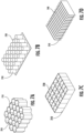
- reinforcement filling 210 includes a honeycomb reinforcement structure 710.
- honeycomb reinforcement structure 710 may be cut into a plurality of corrugated sheets 220.
- honeycomb reinforcement structure 710 is made of a plastic material (e.g., polypropylene). In some examples, honeycomb reinforcement structure 710 provides strength to a roller 100. In some examples, gaps in the honeycomb reinforcement structure 710 allow the roller 100 to be lighter in weight. In some examples, honeycomb reinforcement structure 710 dampens noise produced by roller 100.
- reinforcement filling 210 includes a bubble reinforcement structure 720.
- bubble reinforcement structure 720 may be cut into a plurality of corrugated sheets 220.
- bubble reinforcement structure 720 is made of a plastic material (e.g., polypropylene). In some examples, bubble reinforcement structure 720 provides strength to a roller 100. In some examples, gaps in the bubble reinforcement structure 720 allow the roller 100 to be lighter in weight. In some examples, bubble reinforcement structure 720 dampens noise produced by roller 100.
- a plastic material e.g., polypropylene
- reinforcement filling 210 includes a rectangular reinforcement structure 730.
- rectangular reinforcement structure 730 may be cut into a plurality of corrugated sheets 220.
- rectangular reinforcement structure 730 is made of a plastic material (e.g., polypropylene). In some examples, rectangular reinforcement structure 730 provides strength to a roller 100. In some examples, gaps in the rectangular reinforcement structure 730 allow the roller 100 to be lighter in weight. In some examples, rectangular reinforcement structure 730 dampens noise produced by roller 100.
- plastic material e.g., polypropylene
- reinforcement filling 210 includes a plate reinforcement structure 740.
- plate reinforcement structure 740 may be cut into a plurality of corrugated sheets 220.
- plate reinforcement structure 740 is made of a plastic material (e.g., polypropylene). In some examples, plate reinforcement structure 740 provides strength to a roller 100. In some examples, gaps in the plate reinforcement structure 740 allow the roller 100 to be lighter in weight. In some examples, plate reinforcement structure 740 dampens noise produced by roller 100.
- a roller conveyor system 800 includes one or more conveyor frames 810, one or more conveyor legs 820, and one or more rollers 100.
- a roller conveyor system 800 includes two conveyor frames 810.
- the conveyor frames 810 are positioned perpendicularly to the plurality of rollers 100.
- the conveyor frames 810 extend parallel to each other.
- the conveyor frames are coupled to shafts (e.g., shafts 125 and 135) attached to the one or more rollers 100.
- each conveyor frame 810 is coupled to one or more conveyor legs 820.
- each of the one or more conveyor legs 820 extends perpendicularly to both the plurality of rollers 100 and the plurality of conveyor frames 810.
- each of the conveyor legs 820 includes a bar portion 821 and a foot portion 822.
- the foot portion 822 shaped to provide surface contact with the ground (e.g., a circular shape).
- the foot portion 822 is placed at an end of the bar portion 821 distal to conveyor frame 810.
- the conveyor frames 810, bar portion 821, and/or foot portion 822 may be made of metal.
- foot portion 822 may be made of plastic.
- foot portion 822 may be made of rubber.
Landscapes
- Engineering & Computer Science (AREA)
- Mechanical Engineering (AREA)
- General Engineering & Computer Science (AREA)
- Rollers For Roller Conveyors For Transfer (AREA)
Applications Claiming Priority (2)
| Application Number | Priority Date | Filing Date | Title |
|---|---|---|---|
| IN202311048454 | 2023-07-19 | ||
| US18/459,722 US12473151B2 (en) | 2023-07-19 | 2023-09-01 | Reinforcement to reduce noise and improve flexural strength for metal rollers |
Publications (1)
| Publication Number | Publication Date |
|---|---|
| EP4495031A1 true EP4495031A1 (fr) | 2025-01-22 |
Family
ID=91481786
Family Applications (1)
| Application Number | Title | Priority Date | Filing Date |
|---|---|---|---|
| EP24181520.8A Pending EP4495031A1 (fr) | 2023-07-19 | 2024-06-11 | Renforcement pour réduire le bruit et améliorer la résistance à la flexion pour rouleaux métalliques |
Country Status (1)
| Country | Link |
|---|---|
| EP (1) | EP4495031A1 (fr) |
Citations (3)
| Publication number | Priority date | Publication date | Assignee | Title |
|---|---|---|---|---|
| DE1272218B (de) * | 1967-12-12 | 1968-07-04 | Fritz Teske | Tragrolle fuer Foerdervorrichtungen, Foerderbaender u. dgl. |
| US5766120A (en) * | 1995-03-29 | 1998-06-16 | Voith Sulzer Finishing Gmbh | Calender roller having a cylindrical base body |
| US20070099781A1 (en) * | 2005-10-27 | 2007-05-03 | Tetsuya Itoh | Method for producing motorized roller and motorized roller produced by the method |
-
2024
- 2024-06-11 EP EP24181520.8A patent/EP4495031A1/fr active Pending
Patent Citations (3)
| Publication number | Priority date | Publication date | Assignee | Title |
|---|---|---|---|---|
| DE1272218B (de) * | 1967-12-12 | 1968-07-04 | Fritz Teske | Tragrolle fuer Foerdervorrichtungen, Foerderbaender u. dgl. |
| US5766120A (en) * | 1995-03-29 | 1998-06-16 | Voith Sulzer Finishing Gmbh | Calender roller having a cylindrical base body |
| US20070099781A1 (en) * | 2005-10-27 | 2007-05-03 | Tetsuya Itoh | Method for producing motorized roller and motorized roller produced by the method |
Similar Documents
| Publication | Publication Date | Title |
|---|---|---|
| FI125708B (fi) | Paneelirakenne | |
| US20040105960A1 (en) | Structural sandwich members | |
| US9079377B2 (en) | Sandwich structured construction element | |
| CA3013741C (fr) | Poutre transversale de plancher en composite et methode de fabrication associee | |
| CA2496492A1 (fr) | Feuille de plastique expanse | |
| CA2356724A1 (fr) | Revetement thermoplastique renforce avec du fil metallique | |
| US4742899A (en) | Fiber reinforced tubular component | |
| EP2130762A3 (fr) | Aile et structure de surface portante d'empennage fabriquées en matériau thermoplastique doté d'une configuration à double enveloppe durcie | |
| US10681902B2 (en) | Fishing rod | |
| US12486116B2 (en) | Corrugated reinforced plastic roller | |
| EP1930519A3 (fr) | Panneau en sandwich | |
| US20130336708A1 (en) | Modular structural component | |
| EP1533434A1 (fr) | Panneau de fibres renforcé et procédé de fabrication associé | |
| WO2007127148A2 (fr) | Panneau de coffrage de béton, composite, de poids léger | |
| US12473151B2 (en) | Reinforcement to reduce noise and improve flexural strength for metal rollers | |
| WO2009097836A1 (fr) | Panneau léger comportant un noyau composé de feuilles structurées et des couches de couverture pouvant être coupées | |
| EP4495032A1 (fr) | Rouleau ondulé en matière plastique renforcée | |
| JPH08269886A (ja) | 円筒形基体を有するカレンダロール | |
| EP2360325A1 (fr) | Panneau composite renforcé | |
| CN213167011U (zh) | 一种复合材料压辊结构 | |
| JP2016504534A (ja) | 厚紙を含む構造要素 | |
| JP3322497B2 (ja) | Frp製構造材 | |
| CN1481466A (zh) | 结构元件和制造该元件的方法 | |
| KR100828806B1 (ko) | 자동차용 하이브리드 드라이브샤프트의 제조방법 | |
| WO2015095042A1 (fr) | Guide ou bras de tendeur composite pour application à entraînement synchronisé |
Legal Events
| Date | Code | Title | Description |
|---|---|---|---|
| PUAI | Public reference made under article 153(3) epc to a published international application that has entered the european phase |
Free format text: ORIGINAL CODE: 0009012 |
|
| STAA | Information on the status of an ep patent application or granted ep patent |
Free format text: STATUS: REQUEST FOR EXAMINATION WAS MADE |
|
| 17P | Request for examination filed |
Effective date: 20240611 |
|
| AK | Designated contracting states |
Kind code of ref document: A1 Designated state(s): AL AT BE BG CH CY CZ DE DK EE ES FI FR GB GR HR HU IE IS IT LI LT LU LV MC ME MK MT NL NO PL PT RO RS SE SI SK SM TR |