EP4495055A1 - Système et procédé de traitement de liquide par séparation de molécules du liquide en petites parties - Google Patents
Système et procédé de traitement de liquide par séparation de molécules du liquide en petites parties Download PDFInfo
- Publication number
- EP4495055A1 EP4495055A1 EP23186517.1A EP23186517A EP4495055A1 EP 4495055 A1 EP4495055 A1 EP 4495055A1 EP 23186517 A EP23186517 A EP 23186517A EP 4495055 A1 EP4495055 A1 EP 4495055A1
- Authority
- EP
- European Patent Office
- Prior art keywords
- plates
- liquids
- liquid
- molecules
- treatment units
- Prior art date
- Legal status (The legal status is an assumption and is not a legal conclusion. Google has not performed a legal analysis and makes no representation as to the accuracy of the status listed.)
- Pending
Links
Images


Classifications
-
- C—CHEMISTRY; METALLURGY
- C01—INORGANIC CHEMISTRY
- C01B—NON-METALLIC ELEMENTS; COMPOUNDS THEREOF; METALLOIDS OR COMPOUNDS THEREOF NOT COVERED BY SUBCLASS C01C
- C01B3/00—Hydrogen; Gaseous mixtures containing hydrogen; Separation of hydrogen from mixtures containing it; Purification of hydrogen; Reversible storage of hydrogen
- C01B3/02—Production of hydrogen; Production of gaseous mixtures containing hydrogen
- C01B3/04—Production of hydrogen; Production of gaseous mixtures containing hydrogen by decomposition of inorganic compounds
- C01B3/042—Decomposition of water
-
- B—PERFORMING OPERATIONS; TRANSPORTING
- B01—PHYSICAL OR CHEMICAL PROCESSES OR APPARATUS IN GENERAL
- B01J—CHEMICAL OR PHYSICAL PROCESSES, e.g. CATALYSIS OR COLLOID CHEMISTRY; THEIR RELEVANT APPARATUS
- B01J19/00—Chemical, physical or physico-chemical processes in general; Their relevant apparatus
- B01J19/08—Processes employing the direct application of electric or wave energy, or particle radiation; Apparatus therefor
- B01J19/087—Processes employing the direct application of electric or wave energy, or particle radiation; Apparatus therefor employing electric or magnetic energy
- B01J19/088—Processes employing the direct application of electric or wave energy, or particle radiation; Apparatus therefor employing electric or magnetic energy giving rise to electric discharges
-
- C—CHEMISTRY; METALLURGY
- C01—INORGANIC CHEMISTRY
- C01B—NON-METALLIC ELEMENTS; COMPOUNDS THEREOF; METALLOIDS OR COMPOUNDS THEREOF NOT COVERED BY SUBCLASS C01C
- C01B13/00—Oxygen; Ozone; Oxides or hydroxides in general
- C01B13/02—Preparation of oxygen
- C01B13/0203—Preparation of oxygen from inorganic compounds
- C01B13/0207—Water
-
- C—CHEMISTRY; METALLURGY
- C01—INORGANIC CHEMISTRY
- C01B—NON-METALLIC ELEMENTS; COMPOUNDS THEREOF; METALLOIDS OR COMPOUNDS THEREOF NOT COVERED BY SUBCLASS C01C
- C01B2203/00—Integrated processes for the production of hydrogen or synthesis gas
- C01B2203/04—Integrated processes for the production of hydrogen or synthesis gas containing a purification step for the hydrogen or the synthesis gas
- C01B2203/0465—Composition of the impurity
-
- C—CHEMISTRY; METALLURGY
- C01—INORGANIC CHEMISTRY
- C01B—NON-METALLIC ELEMENTS; COMPOUNDS THEREOF; METALLOIDS OR COMPOUNDS THEREOF NOT COVERED BY SUBCLASS C01C
- C01B2203/00—Integrated processes for the production of hydrogen or synthesis gas
- C01B2203/08—Methods of heating or cooling
- C01B2203/0805—Methods of heating the process for making hydrogen or synthesis gas
- C01B2203/0855—Methods of heating the process for making hydrogen or synthesis gas by electromagnetic heating
Definitions
- the present patent application relates to systems and methods for treating liquids.
- the present patent application relates to splitting molecules of a liquid into smaller parts.
- the current patent application for example, provides a system and method for generation of hydrogen and oxygen gases from water or mixtures of water with other liquids (e.g. an alcohol such as methanol or ethanol).
- oxygen and hydrogen are components of liquids, such as water or mixtures of waters with other liquids (e.g. alcohols), obtaining these components from the liquid is cumbersome.
- the current application provides a novel concept for obtaining hydrogen and oxygen syngas from liquids by splitting molecules of the liquid.
- While various applications of the disclosed concept are possible, one particular example is the application for conditioning liquids for use in internal combustion engines.
- Power units on the basis of internal combustion engines are a main contributor to carbon emissions that accelerate global warming and thereby impact the environment and the air quality, because they combust hydrocarbon fuels which causes emissions such as particulate matter (PM), hydrocarbon (HC), carbon dioxides (CO 2 ), carbon monoxides (CO), and nitrogen oxides (NOX).
- PM particulate matter
- HC hydrocarbon
- CO 2 carbon dioxides
- CO carbon monoxides
- NOX nitrogen oxides
- One way of improving the combustion will be adding hydrogen and/or oxygen gas to the hydrocarbon fuel.
- the system and method according to the current patent application will provide for generating hydrogen or oxygen gas from liquid.
- the system and method according to the current patent application aims at obtaining hydrogen and oxygen gas from widely available liquids, such as (fresh) water, waste water, sea water or any mixture of water and another substance, such as an alcohol, a hydrocarbon fuel or an additive.
- the hydrogen and/or oxygen gas are used as an addition to the hydrocarbon fuel in the combustion engines, the produced hydrogen may also alone be used in respective engines or other application.
- the cumbersome storing facilities like big pressurized gas tanks, become obsolete, since the hydrogen can directly be produced from liquids.
- the abovementioned need for improving the generation of syngas by splitting molecules of a liquid into smaller parts is overcome by an apparatus according to the current invention.
- the apparatus comprises one or more treatment units.
- Each treatment unit of the one or more treatment units comprises two first plates and at least one second plate.
- the two first plates are arranged essentially parallel to each other and each plate of the two first plates comprises at least one hole. Further, the two first plates are configured to receive an electric current.
- the electric current may be provided by an electric current generator or in other words, the first plates may be configured to be connected to an electric current generator.
- the electric current may be an alternating current or may be a direct current.
- the electric current is a pulsating current.
- the first plates may be made of a metal.
- the first plates may be made of stainless steel or another non-magnetic, but conductive metal.
- the first plates may be made of fiber material, such as carbon fibers, or may be made of nano-coated material, including conductive and non-conductive materials, such as glass.
- the at least one second plate is arranged between the two first plates and each second plate comprises at least one hole. Because of their arrangement, the two first plates may be referred to as end plates of the treatment unit, whereas the at least one second plate may be referred to as one or more middle plates.
- the holes of the two first plates and the at least one hole of the at least one second plate are fluidly connected.
- the two first plates and the at least one second plate are arranged essentially parallel to each other.
- the two first plates and the at least one second plate are spaced apart from one another, thereby creating clearances between adjacent plates. These clearances may be fluidly connected by the holes in the first and second plates. This way the clearances and the holes may form one or more flow paths that extend between the plates.
- the holes may be located at opposing ends of the plates, thereby increasing the length of the flow path that is formed between the plates.
- the one or more flow paths that are formed between the plates and the holes may comprise turns in order to increase the length of the flow path.
- one or more liquids will stream through the fluidly connected holes in the first and second plates.
- the liquid By applying an electrical current to the two first plates, the liquid will be polarized.
- the molecules of liquids have portions that are positively charged and other portions that are negatively charged, while the molecule as such is not charged.
- the hydrogen atoms (H) in the molecule get positively charged, while the oxygen atom (O) gets negatively charged because the electronegativity of the oxygen atom is higher than the electronegativity of the hydrogen atoms. Since the water molecule is angled, each water molecule forms a dipole.
- the at least one second plate experiences the electric field generated by the polarization of the one or more liquids and/or the electric field generated by the two first plates. This leads to a polarization of the second pate, thereby maintaining the polarization of the one or more liquids while the one or more liquids flow through the at least one hole in the at least one second plate.
- a pulsating current is applied to the first plates.
- the pulsating current has an amplitude that changes according to a frequency, thereby creating resonance in the liquid molecules. Because of the resonance, energy is introduced into the molecules that causes some of the bonds that hold the atoms of the molecules together to break. When at least some of the bonds are breaking, the molecules of the liquid will split into smaller parts. In case of water, the H 2 O molecules could split into hydrogen and oxygen, which may form H 2 and O 2 molecules dissolved in the water.
- the resonance that is generated by the electric current applied to the first plates may depend on the geometric properties of the apparatus, its size, the arrangement of the plates, and/or the materials used.
- the frequency at which the apparatus resonates is preferably adjusted to match with the frequency that resonates with the bonds of the molecules that are to be split.
- the disclosed apparatus treats liquids by splitting molecules of the liquids into smaller parts.
- hydrogen and oxygen gases are generated from the water or the mixture.
- These hydrogen and oxygen gases may be collected (e.g. separated from the liquid/mixture) and may be used in internal combustion engines or other applications as has been mentioned above.
- the apparatus comprises two or more of the abovementioned treatment units. These two or more treatment units may preferably be arranged in a stacked manner, i.e. arranged adjacent to one another. Thereby, holes in the plates of neighboring treatment units preferably are fluidly connected to one another. As mentioned above, the plates of each treatment unit may be spaced apart and form clearances, wherein the clearances and the holes in the plates form one or more flow paths. In case of two or more treatment units, the flow paths of adjacent treatment units may be connected and form a common flow path.
- a flow path formed between plates of one or more treatment units may form a linear flow path in the sense that the flow path only forms a single branch. While the single branch may comprise turns and twists that increase the length of the flow path and thereby the time during which the liquid flowing through the flow path is treated by the treatment unit, the single branch does not comprise any taps or branch-offs.
- the flow path formed between plates of one or more treatment units may form a branching flow path that comprises multiple branches. This may be of particular use in case that one plate of the treatment units comprises more than one hole, because then the branches of the flow path may connect these different holes with each other.
- multiple flow paths may be formed between the plates of the one or more treatment units. These multiple flow paths may form intersections between at least some of the branches or may be separated without forming any intersections.
- one of the two first plates of a first treatment unit may represent one of the two first plates of a second treatment unit that is an adjacent neighbor of the first treatment unit in the stack of two or more treatment units.
- neighboring treatment units may share a common first plate.
- two neighboring treatment units may comprise a common end plate.
- the abovementioned need is also overcome by a system for treating one or more liquids according to the current invention.
- the system comprises a resonance frequency splitting chamber, a liquid-gas separator, a polarizer and an outlet.
- the resonance frequency splitting chamber may correspond to any of the embodiments of the abovementioned apparatus for treating liquid according to the invention.
- the liquid-gas separator comprises two outputs, wherein a first output may be configured to provide liquid and a second output may provide gas that is separated from the liquid.
- the polarizer may improve the polarization of the one or more liquids and may thereby enhance the further processing of the one or more liquids.
- a polarizer that is suitable for being used in a system according to the invention, is a Halbach array - however other polarizers may be used without departing from the scope of the current application.
- a Halbach array comprises a specific arrangement of permanent magnets, which causes increased magnetic flux on one side of the arrangement, along with highly decreased magnetic flux on the opposite side of the arrangement.
- the Halbach array preferably comprises a cylindrical body. Within the cylindrical body, a stack of rings is placed, wherein each ring comprises magnets that are arranged in an annular fashion along the ring.
- neighboring magnets have opposite orientations, meaning that a first magnet has a north pole facing radially towards the center of the ring and a south pole facing radially outwards of the ring and a neighboring second magnet has a south pole facing radially towards the center of the ring and a north pole facing radially outwards of the rings and so on. Due to this arrangement, the magnetic flux inside the ring may be increased.
- the Halbach array comprises a helical shaped structure that is placed within the stack of rings.
- the helical shaped structure may be made of magnetic material, e.g. stainless steel. However, it is also possible that the helical shaped structure is made of a material that has a chaotic or structured arrangement of magnetic properties, e.g.
- the helical shaped structure is configured to rotate within the stacked rings.
- one or more liquid will be advanced by a rotating movement of helical shaped structure. Because of the increased magnetic flux within the stacked rings, the liquid experiences the influence of the magnetic field lines. When the liquid is advanced through the Halbach array, it will get softer when it streams through the magnetic field on the side of the increased magnetic flux. Thereby, chemical bonds of the liquid may be weakened.
- the resonance frequency splitting chamber, the liquid-gas separator, the polarizer, and the outlet are fluidly connected, wherein the resonance frequency splitting chamber is fluidly connected to the liquid-gas separator, a first output of the two outputs of the liquid-gas separator is connected to the outlet of the system, a second output of the two outputs of the liquid-gas separator is connected to the polarizer, and the polarizer is connected back to the resonance frequency splitting chamber.
- the resonance frequency splitting chamber is fluidly connected to the liquid-gas separator
- a first output of the two outputs of the liquid-gas separator is connected to the outlet of the system
- a second output of the two outputs of the liquid-gas separator is connected to the polarizer
- the polarizer is connected back to the resonance frequency splitting chamber.
- the one or more liquids are treated by splitting molecules of the one or more liquids into smaller parts - in particular splitting water molecules into hydrogen and oxygen - as has been described in detail above with respect to the apparatus according to the invention.
- gaseous content is separated from the one or more liquids, for example hydrogen and oxygen gases are separated from water.
- the water will be provided to the polarizer for conditioning (e.g. by softening the liquid and weakening the chemical bonds of its molecules) and then fed back to the resonance frequency splitting chamber for further treatment, thereby forming a loop for the liquid content.
- the gaseous content that is extracted at the liquid-gas separator is provided to the outlet and can be removed from the system, which allows the gaseous content to be used in other applications.
- the gaseous content may be provided to an internal combustion engine.
- the system may comprise a magnetic gas separator.
- the magnetic gas separator may be connected to the outlet of the system and may separate different gases by applying a magnetic field.
- the magnetic gas separator may comprise a pulsed gradient magnetic field.
- the magnetic gas separator may be configured for separating hydrogen and oxygen gases, thereby allowing the system to not only obtain hydrogen and oxygen gases from a liquid, but also to provide hydrogen gas and oxygen gas as separate products. This way, the system may provide purified hydrogen gas and/or purified oxygen gas.
- the abovementioned need is also overcome by a method for treating one or more liquids according to the current invention.
- the method comprises receiving one or more liquids and treating the one or more liquids by resonance being introduced into the one or more liquids, thereby splitting molecules of the one or more liquids into smaller parts.
- the method may be performed by an apparatus treating one or more liquids according to the current invention or a system for treating one or more liquids according to the current invention that comprises a resonance frequency splitting chamber that corresponds to an apparatus according to the current invention as described above.
- the method may comprise separating the smaller parts obtained from splitting the molecules of the one or more liquids by applying a magnetic field.
- the step of separating the smaller parts may be performed by a magnetic separator.
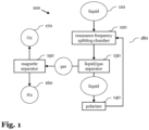
- Figure 1 shows a flow diagram according to an embodiment of the invention.
- the flow diagram according to an embodiment of the invention is generally shown at 100.
- liquids are provided to a system for treating one or more liquids.
- the liquids may include water or a mixture of water and another liquid or substance.
- the substance may be an alcohol, a hydrocarbon fuel, or an additive.
- a resonance frequency splitting chamber 120 receives the liquid and treats the liquid by splitting molecules of the liquid into smaller parts.
- water molecules H 2 O may be split into hydrogen H 2 and oxygen O 2 .
- the products of the splitting may be incorporated in the liquid, for example gaseous hydrogen and gaseous oxygen may be dissolved in the liquid, preferably in form of an emulsion.
- the liquid with the gaseous content is provided to the liquid-gas separator 130 wherein at least a portion of the gaseous content is separated from the liquid and provided to a magnetic separator 150, while the liquid is provided to the polarizer 140 for further processing.
- polarizer 140 While several forms of polarizers may be used, a Halbach array that is used in preferred examples is described in the following. This does, however, not limit the scope of the disclosure.
- the liquid is conditioned by treating it with a magnetic field. By this treatment, the liquid may become softer and the chemical bonds of the liquid molecules may be weakened.
- the conditioned liquid is then fed back to the resonance frequency splitting chamber 120, where it will be mixed with unconditioned liquid received from 110. Thereby, a liquid loop is provided, in which the liquid will flow in a loop between the resonance frequency splitting chamber 120, the liquid-gas separator 130 and the Halbach array, gaseous content dissolved in the liquid will be extracted from the liquid at the liquid-gas separator 130.
- the gaseous content as it is extracted from the liquid at the liquid-gas separator will be the final product of the treatment and will not be further processed. However, in some other embodiments of the system according to the invention, the extracted gaseous content will be further processed.
- the extracted gaseous content is provided to a magnetic separator 150.
- different gases may be separated by ease of magnetic field. Since the splitting of the liquid generally results in a mixture of extracted gases, separating the gases from one another may be necessary in case that purified gases shall be obtained.
- the extracted gas contains a mixture of at least hydrogen and oxygen. Since hydrogen molecules H 2 are diamagnetic (due to paired electrons) and oxygen molecules O 2 are paramagnetic (due to unpaired electrons), both gases will behave differently in a magnetic field.
- the hydrogen and the oxygen molecules will flow differently - for example, when a pulsed gradient magnetic field is applied perpendicular to the flow direction of the gas stream, the diamagnetic hydrogen molecules may only experience a small or no perpendicular force, the paramagnetic oxygen molecules may experience a perpendicular force that may extract the oxygen molecules from the gas stream, thereby separating oxygen and hydrogen from one another.
- a pulsed gradient magnetic field is applied perpendicular to the flow direction of the gas stream
- the diamagnetic hydrogen molecules may only experience a small or no perpendicular force
- the paramagnetic oxygen molecules may experience a perpendicular force that may extract the oxygen molecules from the gas stream, thereby separating oxygen and hydrogen from one another. This concept is illustrated in figure 6 in more detail.
- FIG. 2 shows an embodiment of a resonance frequency splitting chamber as shown in figure 1 , wherein the resonance frequency splitting chamber in the here shown embodiment example comprises a single treatment unit.
- the resonance frequency splitting chamber 200 depicted in figure 2 comprises two first plates 210 and two second plates 220.
- a resonance frequency splitting chamber according to the invention comprises at least one second plate 220.
- two second plates 220 are depicted in figure 2 .
- the two first plates 210 each comprise at least one hole 215 and the two second plates 220 each comprise at least one hole 225. Further, the two first plates 210 are connected to an electric current generator 250.
- Figure 3 shows another embodiment of a resonance frequency splitting chamber that comprises two treatment units.
- the embodiment example depicted in figure 3 comprises two treatment units 300a and 300b, which each comprise a frame formed by dashed lines for illustrative purposes, wherein each of these two treatment units has the same structure as the single treatment unit illustrated in figure 2 .
- the two treatment units 300a and 300b are placed adjacent to one another. In other examples, more than two treatment units may be placed adjacent to one another, thereby forming a stack of treatment units with first and second plates arranged essentially parallel to one another. It can also be said that the two treatment units 300a and 300b are neighboring treatment units.
- both treatment units share a common first plate, namely the first plate that has negative charge in figure 3 .
- each pair of neighboring treatment units may share one of their first plates. While it is not excluded from the scope of the disclosure that two first plates may be placed directly adjacent to one another at the positions where two treatment units are stacked together, using common first plates as is illustrated in figure 3 may be preferred because a smaller number of plates needs to be used.
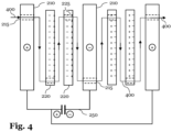
- Figure 4 shows liquid flow through the embodiment of the resonance frequency splitting chamber according to figure 3 .
- liquid flow is illustrated by arrows 400.
- the arrows 400 connect the holes 215 in the first plates 210 and the holes 225 in the second plates 220 with one another. Thereby, a continuous flow path is formed between the holes and clearances between the plates that are spaced apart from one another.
- the holes 215, 225 of neighboring plates are placed at non-overlapping positions, wherein the non-overlapping positions refer to a direction of view that is parallel to the direction in which the plates are stacked. For example in figure 4 , the plates are stacked in a left-right direction.
- the positions of the holes 215, 225 of the embodiment example depicted in figure 4 are alternating between the top portions and bottom portions of the plates, wherein “top” and “bottom” refers to the orientation of the sheet of paper. This way, the distance that the liquid has to cover between the holes of two adjacent plates is increased compared to the case in which the positions of the holes would overlap, which would mean that the flow path would essentially be a left-to-right flow considering the aforementioned directions in figure 4 .
- the liquid will be polarized when it flows along the flow path 400 and is in contact with the first plate 210.
- the polarization of the liquid will also cause a polarization of the second plates 220, which is illustrated via the "+" and "-" placed across the second plates 220 in figure 4 .
- This polarization may be increased in case that the electrical field caused by the first plates 210 is large enough that the second plates 220 experience it as well.
- the polarization of the liquid will be increased over the covered distance.
- Figure 5 shows examples of a Halbach array that may be used as polarizer in the systems according to the invention, e.g. system 100 illustrated in figure 1 .
- Figure 5 (a) is an explosion drawing of a Halbach array according to an embodiment of the invention.
- a Halbach array comprises a specific arrangement of permanent magnets, which causes increased magnetic flux on one side of the arrangement, along with highly decreased magnetic flux on the opposite side of the arrangement.
- Figure 5 illustrates one specific embodiment example of an Halbach array 500 in an explosion drawing.
- the Halbach array 500 comprises a cylindrical body (not shown). Within the cylindrical body, a stack of rings 570 is placed, wherein each ring 570 comprises magnets 590 that are arranged in an annular fashion along the ring. Preferably, neighboring magnets a specified orientation. Some examples of orientations of magnets 590 are illustrated in figure 5 (b) as magnets 590a, 590b, 590c. The arrows represent the magnetic orientation (e.g. pointing from the north pole to the south pole of the magnet). Depending on the orientations of the magnets, the magnetic field within the center of the annularly arranged magnets may be augmented, i.e. increased, oriented in a particular manner or canceled.
- the magnetic field in the center 595a is canceled.
- the field lines of the magnetic field in the center 595b are essentially aligned in a parallel manner and in the example of magnets 590c, the field lines of the magnetic field in the center 595c are arranged in sections as illustrated by the dashed lines.
- the Halbach array 500 comprises a helical shaped structure 580 that is placed within the stack of rings 570.
- the helical shaped structure 580 is preferably made of magnetic material, e.g. stainless steel.
- the helical shaped structure 580 is configured to rotate within the stacked rings 570.
- An inner cylinder 560 may be placed within the stack of rings 570 in order to provide a sealed volume within the stack of rings 570, so that the fluid(s) that are passed through the Halbach array 500 do not leak.
- a rotating movement of helical shaped structure 580 can be used to advance the fluid(s) through the Halbach array 500. Because of the increased magnetic flux within the stacked rings, the fluid(s) experience the influence of the magnetic field lines.
- the Halbach array 500 influences the fluid in a way that the fluid molecules (in particular in case of water molecules) will get softer when they stream through the magnetic field on the side of the increased magnetic flux.
- the Halbach array 500 influences the hydrocarbon fuel in a way that certain chemical bonds of the hydrocarbon chains are weakened, which causes the hydrocarbon chains to dissolve into smaller sections of hydrocarbon chains. As the person skilled in the art will appreciate, burning of smaller hydrocarbon chains will result in reduced amount of exhaust gases, which is why the Halbach array can contribute to the reduction of carbon gas emissions from internal combustion engines.
- Halbach arrays 500 illustrated in Figure 5 (a) and (b) represents only some examples of Halbach arrays and that other Halbach array configurations may be used without departing from the current invention.
- a linear arrangement of magnets 590d as illustrated in Figure 5 (c) may be used in other example of Halbach arrays.
- FIG. 6 shows an embodiment example of a magnetic separator according to an embodiment of the invention, as shown in figure 1 .
- the magnetic separator 600 comprises a pulsed gradient magnetic field that is illustrated as magnetic poles 620a, 620b.
- the magnetic separator may comprise a geometric arrangement that forms pathways for the different gases.
- the geometric arrangement is formed by concentric cylinders 630, 630.
- the inner cylinder 640 may be formed by a mesh tube, thereby allowing gas to flow out of the tube in a radial direction.
- the magnetic separator 600 may separate oxygen molecules 660 from hydrogen molecules 650 since the diamagnetic hydrogen molecules 650 essentially stream through the magnetic separator in a linear manner, while the paramagnetic oxygen molecules 660 may experience a force perpendicular to the direction of the gas stream 610 that pushes the oxygen molecules 660 out of the inner cylinder 640.
Landscapes
- Chemical & Material Sciences (AREA)
- Organic Chemistry (AREA)
- Inorganic Chemistry (AREA)
- Health & Medical Sciences (AREA)
- General Health & Medical Sciences (AREA)
- Toxicology (AREA)
- Chemical Kinetics & Catalysis (AREA)
- Engineering & Computer Science (AREA)
- Combustion & Propulsion (AREA)
- Physical Or Chemical Processes And Apparatus (AREA)
Priority Applications (2)
| Application Number | Priority Date | Filing Date | Title |
|---|---|---|---|
| EP23186517.1A EP4495055A1 (fr) | 2023-07-19 | 2023-07-19 | Système et procédé de traitement de liquide par séparation de molécules du liquide en petites parties |
| PCT/EP2024/070494 WO2025017166A1 (fr) | 2023-07-19 | 2024-07-19 | Système et méthode de traitement de liquide par division de molécules du liquide en parties plus petites |
Applications Claiming Priority (1)
| Application Number | Priority Date | Filing Date | Title |
|---|---|---|---|
| EP23186517.1A EP4495055A1 (fr) | 2023-07-19 | 2023-07-19 | Système et procédé de traitement de liquide par séparation de molécules du liquide en petites parties |
Publications (1)
| Publication Number | Publication Date |
|---|---|
| EP4495055A1 true EP4495055A1 (fr) | 2025-01-22 |
Family
ID=87426543
Family Applications (1)
| Application Number | Title | Priority Date | Filing Date |
|---|---|---|---|
| EP23186517.1A Pending EP4495055A1 (fr) | 2023-07-19 | 2023-07-19 | Système et procédé de traitement de liquide par séparation de molécules du liquide en petites parties |
Country Status (2)
| Country | Link |
|---|---|
| EP (1) | EP4495055A1 (fr) |
| WO (1) | WO2025017166A1 (fr) |
Citations (3)
| Publication number | Priority date | Publication date | Assignee | Title |
|---|---|---|---|---|
| WO1992022679A1 (fr) * | 1991-05-17 | 1992-12-23 | Meyer Stanley A | Systeme d'injection de carburant a eau |
| EP2433902A1 (fr) * | 2009-05-19 | 2012-03-28 | Energy Innovation Company B.V. | Procédé et dispositif de production de gaz combustible, d'énergie thermique, d'hydrogène et d'oxygène |
| US20170275160A1 (en) * | 2016-03-25 | 2017-09-28 | Carter International, Llc | Electro-magnetic resonance apparatus for molecular, atomic, and chemical modification of water |
Family Cites Families (2)
| Publication number | Priority date | Publication date | Assignee | Title |
|---|---|---|---|---|
| PT116152A (pt) * | 2020-03-10 | 2021-09-10 | Fusion Welcome Fuel Unipessoal Lda | Dispositivo com acoplamento directo para geração de hidrogénio a partir de luz solar concentrada |
| US20240044017A1 (en) * | 2020-09-21 | 2024-02-08 | Hysata Pty Ltd | Capillary-based electro-synthetic water electrolysis cells |
-
2023
- 2023-07-19 EP EP23186517.1A patent/EP4495055A1/fr active Pending
-
2024
- 2024-07-19 WO PCT/EP2024/070494 patent/WO2025017166A1/fr active Pending
Patent Citations (3)
| Publication number | Priority date | Publication date | Assignee | Title |
|---|---|---|---|---|
| WO1992022679A1 (fr) * | 1991-05-17 | 1992-12-23 | Meyer Stanley A | Systeme d'injection de carburant a eau |
| EP2433902A1 (fr) * | 2009-05-19 | 2012-03-28 | Energy Innovation Company B.V. | Procédé et dispositif de production de gaz combustible, d'énergie thermique, d'hydrogène et d'oxygène |
| US20170275160A1 (en) * | 2016-03-25 | 2017-09-28 | Carter International, Llc | Electro-magnetic resonance apparatus for molecular, atomic, and chemical modification of water |
Also Published As
| Publication number | Publication date |
|---|---|
| WO2025017166A1 (fr) | 2025-01-23 |
Similar Documents
| Publication | Publication Date | Title |
|---|---|---|
| DK2699786T3 (en) | A method for optimization of internal combustion engines | |
| US5238547A (en) | Gas-liquid separation device for electroconductive gas-liquid two phase flow | |
| JPH04503684A (ja) | 流体の磁気的処理用装置 | |
| RU2671451C2 (ru) | Устройство для обработки жидких и газообразных веществ, содержащих водород и углерод | |
| EP4495055A1 (fr) | Système et procédé de traitement de liquide par séparation de molécules du liquide en petites parties | |
| US20130272927A1 (en) | System and Method for Extracting and Collecting Substances From a Molecular Combination | |
| HK40122415A (en) | System and method for treating liquid by splitting molecules of the liquid into smaller parts | |
| RU2082897C1 (ru) | Магнитный активатор жидких топлив | |
| CN101027471A (zh) | 发动机用磁处理装置以及发动机用磁处理系统 | |
| RU2403211C2 (ru) | Устройство комплексной обработки жидкости | |
| RU2229620C1 (ru) | Устройство для обработки воздуха топливно-воздушной смеси | |
| DK177981B1 (en) | Method and apparatus for increasing gaseous content of a hydrocarbon fuel | |
| JPH06323212A (ja) | 燃料処理のための磁気装置 | |
| US20030113597A1 (en) | Apparatus and method to increase density and energy of hydrogen, oxygen, and other gases | |
| US5243946A (en) | Apparatus for the magnetic treatment of fuel | |
| JP3826199B2 (ja) | 磁気分離装置 | |
| JP7309305B1 (ja) | 気体処理装置 | |
| WO2001073284A1 (fr) | Procede et dispositif de preparation de carburant | |
| CN101900060B (zh) | 高效节油净化器 | |
| RU2403210C2 (ru) | Устройство для обработки жидкости | |
| RU2614562C2 (ru) | Устройство обработки жидкого углеводородного топлива для изменения его группового и фракционного состава под воздействием электрического поля (варианты) | |
| CA2773381A1 (fr) | Methode de traitement du carburant | |
| KR19990034415U (ko) | 자동차용 연료 및 공기 자화장치 | |
| RU219908U1 (ru) | Устройство для обработки углеводородного топлива | |
| CA2526176A1 (fr) | Combustible sous forme de nanogranules et sa preparation |
Legal Events
| Date | Code | Title | Description |
|---|---|---|---|
| PUAI | Public reference made under article 153(3) epc to a published international application that has entered the european phase |
Free format text: ORIGINAL CODE: 0009012 |
|
| STAA | Information on the status of an ep patent application or granted ep patent |
Free format text: STATUS: THE APPLICATION HAS BEEN PUBLISHED |
|
| AK | Designated contracting states |
Kind code of ref document: A1 Designated state(s): AL AT BE BG CH CY CZ DE DK EE ES FI FR GB GR HR HU IE IS IT LI LT LU LV MC ME MK MT NL NO PL PT RO RS SE SI SK SM TR |
|
| STAA | Information on the status of an ep patent application or granted ep patent |
Free format text: STATUS: REQUEST FOR EXAMINATION WAS MADE |
|
| 17P | Request for examination filed |
Effective date: 20250721 |
|
| REG | Reference to a national code |
Ref country code: HK Ref legal event code: DE Ref document number: 40122415 Country of ref document: HK |