EP4495323A1 - Sensorsystem für eine baumaschine - Google Patents
Sensorsystem für eine baumaschine Download PDFInfo
- Publication number
- EP4495323A1 EP4495323A1 EP23185833.3A EP23185833A EP4495323A1 EP 4495323 A1 EP4495323 A1 EP 4495323A1 EP 23185833 A EP23185833 A EP 23185833A EP 4495323 A1 EP4495323 A1 EP 4495323A1
- Authority
- EP
- European Patent Office
- Prior art keywords
- construction machine
- pattern
- sensor system
- edge
- previous
- Prior art date
- Legal status (The legal status is an assumption and is not a legal conclusion. Google has not performed a legal analysis and makes no representation as to the accuracy of the status listed.)
- Pending
Links
Images


Classifications
-
- E—FIXED CONSTRUCTIONS
- E01—CONSTRUCTION OF ROADS, RAILWAYS, OR BRIDGES
- E01C—CONSTRUCTION OF, OR SURFACES FOR, ROADS, SPORTS GROUNDS, OR THE LIKE; MACHINES OR AUXILIARY TOOLS FOR CONSTRUCTION OR REPAIR
- E01C19/00—Machines, tools or auxiliary devices for preparing or distributing paving materials, for working the placed materials, or for forming, consolidating, or finishing the paving
- E01C19/004—Devices for guiding or controlling the machines along a predetermined path
- E01C19/006—Devices for guiding or controlling the machines along a predetermined path by laser or ultrasound
-
- E—FIXED CONSTRUCTIONS
- E01—CONSTRUCTION OF ROADS, RAILWAYS, OR BRIDGES
- E01C—CONSTRUCTION OF, OR SURFACES FOR, ROADS, SPORTS GROUNDS, OR THE LIKE; MACHINES OR AUXILIARY TOOLS FOR CONSTRUCTION OR REPAIR
- E01C19/00—Machines, tools or auxiliary devices for preparing or distributing paving materials, for working the placed materials, or for forming, consolidating, or finishing the paving
- E01C19/12—Machines, tools or auxiliary devices for preparing or distributing paving materials, for working the placed materials, or for forming, consolidating, or finishing the paving for distributing granular or liquid materials
-
- G—PHYSICS
- G01—MEASURING; TESTING
- G01S—RADIO DIRECTION-FINDING; RADIO NAVIGATION; DETERMINING DISTANCE OR VELOCITY BY USE OF RADIO WAVES; LOCATING OR PRESENCE-DETECTING BY USE OF THE REFLECTION OR RERADIATION OF RADIO WAVES; ANALOGOUS ARRANGEMENTS USING OTHER WAVES
- G01S17/00—Systems using the reflection or reradiation of electromagnetic waves other than radio waves, e.g. lidar systems
- G01S17/02—Systems using the reflection of electromagnetic waves other than radio waves
- G01S17/06—Systems determining position data of a target
- G01S17/42—Simultaneous measurement of distance and other co-ordinates
-
- G—PHYSICS
- G01—MEASURING; TESTING
- G01S—RADIO DIRECTION-FINDING; RADIO NAVIGATION; DETERMINING DISTANCE OR VELOCITY BY USE OF RADIO WAVES; LOCATING OR PRESENCE-DETECTING BY USE OF THE REFLECTION OR RERADIATION OF RADIO WAVES; ANALOGOUS ARRANGEMENTS USING OTHER WAVES
- G01S17/00—Systems using the reflection or reradiation of electromagnetic waves other than radio waves, e.g. lidar systems
- G01S17/88—Lidar systems specially adapted for specific applications
- G01S17/93—Lidar systems specially adapted for specific applications for anti-collision purposes
- G01S17/931—Lidar systems specially adapted for specific applications for anti-collision purposes of land vehicles
-
- G—PHYSICS
- G01—MEASURING; TESTING
- G01S—RADIO DIRECTION-FINDING; RADIO NAVIGATION; DETERMINING DISTANCE OR VELOCITY BY USE OF RADIO WAVES; LOCATING OR PRESENCE-DETECTING BY USE OF THE REFLECTION OR RERADIATION OF RADIO WAVES; ANALOGOUS ARRANGEMENTS USING OTHER WAVES
- G01S7/00—Details of systems according to groups G01S13/00, G01S15/00, G01S17/00
- G01S7/48—Details of systems according to groups G01S13/00, G01S15/00, G01S17/00 of systems according to group G01S17/00
- G01S7/481—Constructional features, e.g. arrangements of optical elements
- G01S7/4811—Constructional features, e.g. arrangements of optical elements common to transmitter and receiver
-
- E—FIXED CONSTRUCTIONS
- E01—CONSTRUCTION OF ROADS, RAILWAYS, OR BRIDGES
- E01C—CONSTRUCTION OF, OR SURFACES FOR, ROADS, SPORTS GROUNDS, OR THE LIKE; MACHINES OR AUXILIARY TOOLS FOR CONSTRUCTION OR REPAIR
- E01C19/00—Machines, tools or auxiliary devices for preparing or distributing paving materials, for working the placed materials, or for forming, consolidating, or finishing the paving
- E01C19/48—Machines, tools or auxiliary devices for preparing or distributing paving materials, for working the placed materials, or for forming, consolidating, or finishing the paving for laying-down the materials and consolidating them, or finishing the surface, e.g. slip forms therefor, forming kerbs or gutters in a continuous operation in situ
Definitions
- Embodiments of the present invention refer to a sensor system, especially to a sensor system for a construction machine, especially a road construction machine or paving machine.
- An embodiment refers to a corresponding method and computer program.
- Another embodiment refers to a construction machine comprising a sensor system.
- embodiments of the present invention are in the field of measurement equipment, especially LiDAR or laser measurement equipment.
- LiDAR / laser sensors are used to detect and track a reference along which the paver (paving machine / road finishing machine) itself or equipment of the paver, like the screed, can be controlled.
- the paver can be controlled with regard to its lateral dynamics by use of a reference which extends along the traveling direction.
- a rope or stone edge curb extending along the traveling direction can be used as reference.
- the road finishing machine driver makes steering corrections (manually, or autonomously/semi-autonomously) in accordance with a specific reference, such that the road finishing machine travels as parallel as possible at the same distance from the reference. Automation of the entire steering process (tractor and plank/screed) would significantly reduce the workload of the road finishing machine's operation during asphalt paving.
- An exemplary approach is described in the WO 2020/088782 A1 .
- Embodiments of the present invention provide a sensor system for a construction machine, like a road construction machine or paving machine.
- the sensor system comprises an optical detector which is arrangeable on the construction machine and a processor.
- the detector is configured to scan the underground in a predetermined angle so as to obtain measurement data describing one or more intensity values and/or one or more distance values plotted over the predetermined angle range.
- the processor is configured to analyse the measurement data so as to determine a pattern of intensity values and/or distance values in accordance with a predetermined pattern out of one or more predetermined patterns.
- the pattern to be determined can be a milling edge pattern.
- the one or more predetermined patterns comprising a milling edge pattern characterized by two plateaus with a connection in between.
- the connection might be substantially perpendicular or may have an inclination angle within a range between 70° to 90° or 70° to 100° or, in general, larger than 70° or preferably larger than 80°.
- a paving edge pattern may be determined.
- the one or more predetermined patterns comprise a paving edge pattern characterized by two plateaus having a connection in between, wherein the connection has an inclination angle less than 70°.
- the pattern may be the pattern of a curb stone edge.
- the one or more predetermined patterns comprise the curb stone edge pattern characterized by two plateaus having a connection in between or a substantially perpendicular connection in between, wherein one edge comprises a roundness and/or wherein a spacing between the two edges is larger than 5 cm or 10 cm.
- the patterns for other kinds of edges which are known and stored as predetermined patterns.
- the above mentioned predetermined patterns may be stored in a database being part of the sensor system or being connected to the processor of the sensor system.
- the optical detector is configured to scan the underground to be paved or paved across a traveling direction of the construction machine and/or angled by an angle arranged between 45° and 90° with respect to the traveling direction of the construction machine.
- the optical detector is configured to scan the underground to be repaved or paved along a direction crossing the traveling direction of the construction machine and/or along a plurality of positions along the traveling direction of the construction machine.
- the optical detector is arranged at the side of the paver so that it can scan the area sidewise to the construction machine.
- the scanner performs the scanning, wherein due to the movement along the traveling direction a scan along the traveling direction is caused, while the scanner is configured to scan the predetermined angle to the side.
- the predetermined angle is predetermined by the optical sensor.
- the scanning plane is arranged perpendicular to the traveling direction or crosses a traveling direction a scanning across the traveling direction is possible.
- the optical detector comprises a LiDAR sensor and/or laser scanner.
- the controller is configured to set and/or determine a control point in relation to the pattern or a curb within the pattern or in relation to a user terminal spacing to the curb within the pattern.
- the processor is configured to determine the pattern within a plurality of measurement data (sets) to be determined along a traveling direction and/or during a plurality of subsequent points of time. Alternatively or additionally, the processor is configured to track a control point determined within the pattern along the traveling direction and/or along a plurality of measurements determined in a plurality of subsequent points of time.
- the processor is configured to perform a predetermination of one or more patterns during a teach in phase and/or during a training phase and/or during a training phase performed using artificial intelligence.
- the processor is configured to automatically determine a control point and/or a relation or lateral spacing to the control point or between the control point and the construction machine so as to output an information on the spacing or lateral spacing to the control point of the construction machine.
- Another embodiment provides a construction machine, especially a road construction machine or paving machine comprising a sensor system according to embodiments of the present invention.
- the construction machine may, according to further embodiments, comprise a controller for performing autonomous and/or semi-autonomous and/or automated controlling based on measurement data provided by the sensor system.
- Another embodiment provides a method for performing curb detection.
- the method comprises the following steps:
- the method may be computer implemented.
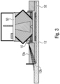
- Fig. 1 shows an optical detector module 10 like a laser scanner, together with a processor 20.
- the optical detector 10 is arrangeable on a construction machine, like a road construction machine or paving machine 50 as is illustrated by Fig. 3 .
- the optical detector 10 is configured to scan the underground 12 which comprises the edge 12k.
- the underground 12 is scanned within a predetermined range 10a so as to obtain measurement data.
- the measurement data comprises an information on a measured distance between the scanner 10 and the underground 12 plotted over the angles of the predetermined scan angle 10a.
- intensity values can be obtained.
- the edge 12k causes a kind of discontinuity with respect to the distance values and/or intensity values.
- the height of the edge 12k and/or the flag angle are dependent on the type of curb. Vice versa, this means that different curbs 12k on or within the underground 12 cause different patterns within the measurement data.
- Such a pattern can be predetermined so that the measurement data can be compared with the one or more predetermined pattern so as to characterize the respective curb
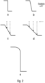
- Figs. 2a to 2e five different predetermined patterns will be discussed which can be determined by the sensor system of Fig. 1 .
- Figs. 2a to 2e show different edge shapes.
- Figs. 2a and 2b show two different milling edges, wherein the angle is in the range between 70° (cf. Fig. 2b ) and 90° (cf. Fig. 2a ).
- a scan of the two milling edges of 2a and 2b would result in a pattern having two plateaus with a perpendicular or steep slope in between.
- the angle can be 70° of the slope. This means that the angle between the plateau and the connection amounts to 90° to 110°.
- the distance values as well as the intensity values would indicate this shape.
- the transition of the plateaus of Fig. 2a and 2b comprises a kind of jump.
- Figs. 2c and 2d show two different edges, namely paving edges, where the slope is below 70°. Consequently, the angle between the two plateaus and the connection line is larger than 110°. Due to this the pattern comprises a "continuous" transition from the one plateau to the next plateau. The transition / slope is dependent on the shape of the sent element of the screed.
- Fig. 2c to 2d scan directions for the case that the optical scanner is arranged above are shown.
- the slope can be detected by use of the distance values and/or the intensity values.
- the distance values as well as intensity values have a specific pattern which can be predetermined and compared afterwards.
- the pattern is different.
- the characteristics are the same and, for optical sensors being arranged with a diagonal view, can also be predetermined.
- Fig. 2e shows another edge, namely a so-called curb stone edge.
- two plateaus with a connection in between are arranged wherein the connection is substantially larger when compared to the connection of the edge of Fig. 2a, 2b, 2c and/or 2d.
- the edge may have a rounding at the top plateau.
- the processor 20 comprises a database having stored thereon one or more predetermined patterns and is configured to analyse the measurement data detected using the sensor 10 by comparing the measurement data/pattern of distance values/intensity values within the measurement data with predetermined patterns so as to find out whether the determined pattern complies to a pattern being stored before.
- the paving machine is configured to provide a pavement on the underground 12 by use of the screed 52.
- the underground 12 may comprise an edge 12k which can be determined by the optical sensor 10.
- the optical sensor 10 scans the underground 12 within a predetermined angle 10a so as to determine the edge 12k and the type of the edge.
- the optical detector 10 is arranged on the side, e.g., on the screed 52 or a side blade of the screed 52 and focussed on the underground 12.
- the measurement angle is approximately 100° with respect to the traveling direction.
- the predetermined angle ⁇ of the sensor 10 in this embodiment is not arranged as a bird view perpendicular to the ground but slightly inclined, e.g., by 45° or even 60° to the ground.
- Fig. 4a illustrates the pattern recognition of a milling edge 54k by means of the laser scanner 10 from the side.
- the laser scanner 10 again scans with a scanning range of 15 to 45 degrees or of 15 to 30 degrees.
- the milling edge 54k also provides a special pattern which can be used to unambiguously determine the distance to the milling edge 54k. This is to be explained in Fig. 4b such that the pattern of the milling edge can be detected across successive identical measurement values with a relatively high signal amplitude. Looking at the waveforms of the signal strength 15s and the measurement distance 15a shown in Fig. 4b , the special pattern recognition of the waveforms becomes clear.
- a corresponding detection or evaluation algorithm detects the slight superelevation of the signal strength 15sp in the scanning range 17, which represents the measurement angle for the milling edge 54h. Additionally or alternatively, the evaluation algorithm can also detect approximately equal distance values 15a in this scanning range 17.
- the pattern recognition of a milling edge from the side consists of detecting a lateral superelevation (cf. reference number 15s) as in the case of the signal strength and/or a plateau 15ap for the distance measurement value 15a, wherein 15sp and 15ap occur essentially in the same measurement range/angular range 17.
- the plateau 15ap also simultaneously represents the measurement distance to the milling edge to be evaluated.
- Fig. 4c shows the same edge 12k but from a different point of view, namely the point of view where the optical detector 10 is not inclined with respect to the ground, like what is shown in Figs. 4a and 3 , but directed perpendicular to the ground.
- Fig. 4c the pattern recognition of a milling edge 54k from above is explained.
- the laser scanner 10 is arranged above the milling edge 54k.
- the resulting waveform is shown in Fig. 4d .
- evaluation of the milling edge 54k from above results in a relatively large scan angle (e.g. 30° to 50°) of measurement values to the signal strength 15s and to the measurement distance 15a with high signal amplitude.
- scan angle e.g. 30° to 50°
- there is a measurement value jump 15ss from h1 to h2 at the position of the milling edge. This jump provides the exact position of the milling edge in relation to the measurement angle (here: ⁇ 0 degrees).
- the scan angle at which the height jump from h1 to h2 occurs is the scan angle at which the height jump from h1 to h2 occurs.
- the distance measurement is used here only to detect the change in distance from h1 to h2.
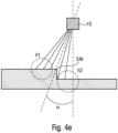
- the scan angle can also be converted into a distance value (lateral or vertical distance), as can be seen from Fig. 4d and 4e .
- Fig. 4e the situation of Fig. 4c is shown, wherein, however, the scanner 10 is not arranged vertically above, but laterally offset with respect to the milling edge 54k.
- the signal pattern from Fig. 4d is relevant for the distance calculation to the reference.
- the measurement distance to the reference can therefore be calculated in the same way as the tangent value, so that the distance value a determined in this way in the X direction (lateral) represents the distance to the zero reference. While the zero reference is determined in the laser scanner, the laser scanner 10 should be installed during setup so that the distance value a is as close to zero as possible.
- Fig. 4e show another point of view where the sensor 10 is likely inclined with respect to the edge 12k.
- the pattern of height and/or intensity values can differ with respect to the angle formed between the edge to be detected and the detector.
- the quality of the formed edge can be determined. Since the measurement is performed during subsequent points of time during which the construction machine travels along the traveling direction, different positions of the edge are scanned. This enables that deviations from the current geometry can be determined. Furthermore, interactions of the edge can be determined. According to embodiments, different predetermined patterns for different quality levels of one edge type can be used so as to determine the quality by use of a predetermined pattern.
- control point is adjustable to the shown positions or between the shown positions.
- the control point can be set during an initial starting phase. For example, when an edge type is determined the user may be asked to set the control point or confirm the control point which was automatically set by the controller 20.
- aspects have been described in the context of an apparatus, it is clear that these aspects also represent a description of the corresponding method, where a block or device corresponds to a method step or a feature of a method step. Analogously, aspects described in the context of a method step also represent a description of a corresponding block or item or feature of a corresponding apparatus.
- Some or all of the method steps may be executed by (or using) a hardware apparatus, like for example, a microprocessor, a programmable computer or an electronic circuit. In some embodiments, some one or more of the most important method steps may be executed by such an apparatus.
- Some embodiments according to the invention comprise a data carrier having electronically readable control signals, which are capable of cooperating with a programmable computer system, such that one of the methods described herein is performed.
- embodiments of the present invention can be implemented as a computer program product with a program code, the program code being operative for performing one of the methods when the computer program product runs on a computer.
- the program code may for example be stored on a machine readable carrier.
- an embodiment of the inventive method is, therefore, a computer program having a program code for performing one of the methods described herein, when the computer program runs on a computer.
- a further embodiment comprises a processing means, for example a computer, or a programmable logic device, configured to or adapted to perform one of the methods described herein.
- a processing means for example a computer, or a programmable logic device, configured to or adapted to perform one of the methods described herein.
- a further embodiment comprises a computer having installed thereon the computer program for performing one of the methods described herein.
- a programmable logic device for example a field programmable gate array
- a field programmable gate array may cooperate with a microprocessor in order to perform one of the methods described herein.
- the methods are preferably performed by any hardware apparatus.
Landscapes
- Engineering & Computer Science (AREA)
- Physics & Mathematics (AREA)
- Computer Networks & Wireless Communication (AREA)
- General Physics & Mathematics (AREA)
- Radar, Positioning & Navigation (AREA)
- Remote Sensing (AREA)
- Electromagnetism (AREA)
- Architecture (AREA)
- Civil Engineering (AREA)
- Structural Engineering (AREA)
- Optics & Photonics (AREA)
- Length Measuring Devices By Optical Means (AREA)
- Road Repair (AREA)
Priority Applications (3)
| Application Number | Priority Date | Filing Date | Title |
|---|---|---|---|
| EP23185833.3A EP4495323A1 (de) | 2023-07-17 | 2023-07-17 | Sensorsystem für eine baumaschine |
| CN202410952967.3A CN119322350A (zh) | 2023-07-17 | 2024-07-16 | 传感器系统 |
| US18/774,667 US12529193B2 (en) | 2023-07-17 | 2024-07-16 | Sensor system |
Applications Claiming Priority (1)
| Application Number | Priority Date | Filing Date | Title |
|---|---|---|---|
| EP23185833.3A EP4495323A1 (de) | 2023-07-17 | 2023-07-17 | Sensorsystem für eine baumaschine |
Publications (1)
| Publication Number | Publication Date |
|---|---|
| EP4495323A1 true EP4495323A1 (de) | 2025-01-22 |
Family
ID=87378029
Family Applications (1)
| Application Number | Title | Priority Date | Filing Date |
|---|---|---|---|
| EP23185833.3A Pending EP4495323A1 (de) | 2023-07-17 | 2023-07-17 | Sensorsystem für eine baumaschine |
Country Status (3)
| Country | Link |
|---|---|
| US (1) | US12529193B2 (de) |
| EP (1) | EP4495323A1 (de) |
| CN (1) | CN119322350A (de) |
Citations (3)
| Publication number | Priority date | Publication date | Assignee | Title |
|---|---|---|---|---|
| US9529087B2 (en) * | 2014-07-24 | 2016-12-27 | GM Global Technology Operations LLC | Curb detection using lidar with sparse measurements |
| WO2020088782A1 (de) | 2018-11-02 | 2020-05-07 | Moba Mobile Automation Ag | SENSORSYSTEM FÜR EINEN STRAßENFERTIGER |
| US20230004744A1 (en) * | 2021-06-30 | 2023-01-05 | Zoox, Inc. | Techniques for identifying curbs |
Family Cites Families (64)
| Publication number | Priority date | Publication date | Assignee | Title |
|---|---|---|---|---|
| US3334560A (en) | 1964-05-25 | 1967-08-08 | George E Long | Control system for establishing predetermined surfaces |
| US3908765A (en) | 1973-03-01 | 1975-09-30 | Honeywell Inc | Floating position proportional control system |
| GB8313339D0 (en) | 1983-05-14 | 1983-06-22 | Gen Electric Co Plc | Vehicle guidance |
| JPH02136405A (ja) | 1988-11-15 | 1990-05-25 | Sumitomo Heavy Ind Ltd | 舗装厚検出装置 |
| JPH0749642B2 (ja) | 1990-11-14 | 1995-05-31 | 株式会社新潟鐵工所 | 敷均し機械における舗装厚制御方法 |
| JPH0749641B2 (ja) | 1990-11-14 | 1995-05-31 | 株式会社新潟鐵工所 | 敷均し機械における舗装厚制御方法 |
| KR100206726B1 (ko) | 1990-11-14 | 1999-07-01 | 와시오히데오 | 포장 기계에 있어서의 포장 두께 제어방법 및 자동 제어의 조건 설정방법 |
| US5327345A (en) | 1991-02-15 | 1994-07-05 | Laser Alignment, Inc. | Position control system for a construction implement such as a road grader |
| DE9214769U1 (de) | 1991-11-15 | 1993-04-01 | MOBA - Electronic Gesellschaft für Mobil-Automation mbH, 65604 Elz | Ultraschallsensor-Regeleinrichtung für einen Straßenfertiger |
| US5356238A (en) | 1993-03-10 | 1994-10-18 | Cedarapids, Inc. | Paver with material supply and mat grade and slope quality control apparatus and method |
| JP2505210Y2 (ja) | 1993-04-09 | 1996-07-24 | 建設省東北地方建設局長 | 舗装作業車の自動操向装置 |
| US5484227A (en) | 1993-04-09 | 1996-01-16 | Niigata Engineering Co., Ltd. | Control device for asphalt finisher |
| US5721685A (en) | 1995-06-29 | 1998-02-24 | Holland; Robert E. | Digi-track digital roadway and railway analyzer |
| US6287048B1 (en) | 1996-08-20 | 2001-09-11 | Edmund D. Hollon | Uniform compaction of asphalt concrete |
| DE29723171U1 (de) | 1997-03-06 | 1998-04-23 | ABG Allgemeine Baumaschinen-Gesellschaft mbH, 31785 Hameln | Walzeneinrichtung zur Verdichtung von Asphaltdecken |
| DE19755324A1 (de) | 1997-12-12 | 1999-06-17 | Michael Dipl Ing Sartori | Verfahren und Vorrichtung zum Steuern eines Fahrzeugs |
| US5975473A (en) | 1998-03-12 | 1999-11-02 | Topcon Laser Systems, Inc. | Mounting device for non-contacting sensors |
| US5984420A (en) | 1998-05-29 | 1999-11-16 | Wirtgen America, Inc. | Grade averaging system with floating boom and method of using the same |
| DE19951296C2 (de) | 1999-10-25 | 2003-09-25 | Moba Mobile Automation Gmbh | Vorrichtung und Verfahren zum Steuern eines Strassenfertigers |
| DK1118713T3 (da) | 2000-01-19 | 2005-01-10 | Joseph Voegele Ag | Fremgangsmåde til styring af en entreprenörmaskine og en vejlægningsmaskine samt vejlægningsmaskine |
| DE10038943A1 (de) | 2000-08-09 | 2002-02-21 | Joseph Voegele Ag | Strassenfertiger und Einbauverfahren |
| DE10060903C2 (de) | 2000-12-07 | 2002-10-31 | Moba Mobile Automation Gmbh | Laser-Höhenregeleinrichtung für eine Baumaschine |
| DE10138563B4 (de) | 2001-08-06 | 2010-01-14 | Joseph Voegele Ag | Rad-Straßenfertiger und Verfahren zum Lenken eines Rad-Straßenfertigers |
| DE10234217B4 (de) | 2002-07-27 | 2009-02-05 | Hermann Kirchner Gmbh & Co Kg | Verfahren und Vorrichtung zur Ermittlung der Dicke einer Asphaltschicht |
| DE10242645A1 (de) | 2002-09-13 | 2004-03-25 | Magcode Ag | Verfahren und Vorrichtung zur Herstellung einer elektrischen Verbindung von Baugruppen und Modulen |
| ATE393263T1 (de) | 2002-09-25 | 2008-05-15 | Tecnologia Maquinaria Y Compon | Trag- und positionseinstellkonstruktion für eine automatische niveauregelanlage |
| US7172363B2 (en) | 2004-08-31 | 2007-02-06 | Caterpillar Paving Products Inc | Paving machine output monitoring system |
| DE102005022266A1 (de) | 2005-05-10 | 2006-11-16 | Abg Allgemeine Baumaschinen-Gesellschaft Mbh | Fertiger zum bodenseitigen Einbau von Schichten für Straßen oder dgl. |
| DE102006039799B3 (de) | 2006-08-24 | 2007-11-22 | Tyco Electronics Amp Gmbh | Elektrischer Stecker |
| EP2006448A1 (de) | 2007-06-21 | 2008-12-24 | Leica Geosystems AG | Einbauzug zum erstellen einer Belagschicht aus Beton- oder Asphalt-Material |
| US8132935B2 (en) | 2008-09-01 | 2012-03-13 | Samsung Led Co., Ltd. | Light emitting module |
| CN201660836U (zh) | 2010-02-02 | 2010-12-01 | 德国Moba自动控制股份有限公司 | 非接触式平衡梁机械支架 |
| US8371769B2 (en) | 2010-04-14 | 2013-02-12 | Caterpillar Trimble Control Technologies Llc | Paving machine control and method |
| CN201770931U (zh) | 2010-06-13 | 2011-03-23 | 江苏四明工程机械有限公司 | 用于路面机械的非接触超声波平均找平梁 |
| TWI415332B (zh) | 2010-12-31 | 2013-11-11 | Lextar Electronics Corp | 電子電路模組及電性連接器 |
| EP2511781A1 (de) | 2011-04-14 | 2012-10-17 | Hexagon Technology Center GmbH | System und Verfahren zur Steuerung eines unbemannten Fluggeräts |
| EP2535458B2 (de) | 2011-06-15 | 2020-04-29 | Joseph Vögele AG | Straßenfertiger mit Schichtdickenmessvorrichtung |
| EP2535456B1 (de) | 2011-06-15 | 2013-12-18 | Joseph Vögele AG | Straßenfertiger mit Schichtdickenmessvorrichtung |
| EP2756561B1 (de) | 2011-09-16 | 2018-09-12 | Amphenol FCI Asia Pte. Ltd. | Schwenkbare verbinderanordnung |
| DE102011113752B4 (de) | 2011-09-19 | 2021-05-06 | Bomag Gmbh | Fräsvorrichtung mit einer Sensoreinrichtung zur Fräskantenerkennung, Verfahren zur Fräskantenerkennung und Sensoreneinrichtung zur Fräskantenerkennung. |
| DE102011119272A1 (de) | 2011-11-24 | 2013-05-29 | Thomas Tennagels | Magnetischer Entkupplungsmechanismus für aneinander zu reihende leistenförmige Profile sowie Leisten mit einem derartigen Entkupplungsmechanismus |
| US8944719B2 (en) | 2012-11-09 | 2015-02-03 | Caterpillar Paving Products Inc. | Tracking of machine system movements in paving machine |
| EP2743399B1 (de) | 2012-12-14 | 2015-09-30 | Joseph Vögele AG | Baumaschine mit Einrichthilfesystem für eine Sensoreinheit |
| DE102013008701B3 (de) | 2013-05-22 | 2014-10-09 | Audi Ag | Verfahren zum Betreiben einer Getriebeeinrichtung sowie entsprechende Getriebeeinrichtung |
| JP5709185B2 (ja) | 2013-08-22 | 2015-04-30 | 鹿島道路株式会社 | 敷き均し方法 |
| EP2869095B1 (de) | 2013-10-29 | 2016-12-07 | Sick Ag | Optoelektronischer Sensor |
| CN104833367A (zh) | 2015-05-11 | 2015-08-12 | 京东方科技集团股份有限公司 | 车载投影系统 |
| WO2016199312A1 (ja) | 2015-06-10 | 2016-12-15 | 株式会社Doog | 自律移動システム |
| EP3106562A1 (de) | 2015-06-19 | 2016-12-21 | TF-Technologies A/S | Korrektureinheit |
| DE102015008315A1 (de) | 2015-06-30 | 2017-01-05 | Dynapac Gmbh | Einbaubohle und Straßenfertiger |
| EP3130939A1 (de) | 2015-08-13 | 2017-02-15 | Joseph Vögele AG | Strassenfertiger mit einer radarbasierten nivelliereinrichtung und steuerverfahren |
| DE102015216060A1 (de) | 2015-08-21 | 2017-02-23 | Mts Maschinentechnik Schrode Ag | Verbindungsanordnung |
| DE202016100093U1 (de) | 2016-01-12 | 2017-04-20 | Joseph Vögele AG | Straßenfertiger mit Projektor als Navigationshilfe |
| PL3228747T3 (pl) | 2016-04-08 | 2018-11-30 | Joseph Vögele AG | Wykańczarka z urządzeniem przytrzymującym dla podtrzymywania i pozycjonowania jednostki czujnikowej |
| EP3382098B1 (de) | 2017-03-29 | 2019-03-27 | Joseph Vögele AG | Strassenfertiger mit haltevorrichtung zum tragen und positionieren einer sensoreinheit |
| DE102017010238A1 (de) | 2017-11-03 | 2019-05-09 | Bomag Gmbh | Messung der Einbauschichtdicke durch Straßenwalze |
| CN109356005A (zh) | 2018-12-07 | 2019-02-19 | 石家庄辰启科技有限公司 | 摊铺机熨平板平衡测控系统及摊铺机 |
| EP3712328B1 (de) | 2019-03-20 | 2022-11-23 | MOBA Mobile Automation AG | Baumaschine mit messsystem |
| EP3835485B1 (de) | 2019-12-11 | 2022-08-24 | MOBA Mobile Automation AG | Messsystem für eine baumaschine |
| CN115917245A (en) | 2020-01-31 | 2023-04-04 | 摩巴自动控制股份有限公司 | Measurement system and controller |
| US11550058B2 (en) | 2020-04-10 | 2023-01-10 | Caterpillar Paving Products Inc. | Perception system three lidar coverage |
| US11810364B2 (en) | 2020-08-10 | 2023-11-07 | Volvo Car Corporation | Automated road damage detection |
| WO2022037764A1 (de) | 2020-08-18 | 2022-02-24 | Moba Mobile Automation Ag | MESSSYSTEM FÜR EINE STRAßENBAUMASCHINE |
| CN113152215A (zh) | 2021-06-01 | 2021-07-23 | 山推工程机械股份有限公司 | 一种压路机贴边系统 |
-
2023
- 2023-07-17 EP EP23185833.3A patent/EP4495323A1/de active Pending
-
2024
- 2024-07-16 US US18/774,667 patent/US12529193B2/en active Active
- 2024-07-16 CN CN202410952967.3A patent/CN119322350A/zh active Pending
Patent Citations (3)
| Publication number | Priority date | Publication date | Assignee | Title |
|---|---|---|---|---|
| US9529087B2 (en) * | 2014-07-24 | 2016-12-27 | GM Global Technology Operations LLC | Curb detection using lidar with sparse measurements |
| WO2020088782A1 (de) | 2018-11-02 | 2020-05-07 | Moba Mobile Automation Ag | SENSORSYSTEM FÜR EINEN STRAßENFERTIGER |
| US20230004744A1 (en) * | 2021-06-30 | 2023-01-05 | Zoox, Inc. | Techniques for identifying curbs |
Also Published As
| Publication number | Publication date |
|---|---|
| CN119322350A (zh) | 2025-01-17 |
| US20250027278A1 (en) | 2025-01-23 |
| US12529193B2 (en) | 2026-01-20 |
Similar Documents
| Publication | Publication Date | Title |
|---|---|---|
| US11885881B2 (en) | Sensor system for a road finishing machine | |
| EP3576008B1 (de) | Bildbasierte fahrbahnmarkierungsklassifizierung | |
| EP0827127B1 (de) | Lokales Positionierungsgerät und Verfahren dafür | |
| US8085984B2 (en) | Image recognizing apparatus and method, and position determining apparatus, vehicle controlling apparatus and navigation apparatus using the image recognizing apparatus or method | |
| JP4327389B2 (ja) | 走行レーン認識装置 | |
| US8736820B2 (en) | Apparatus and method for distinguishing ground and obstacles for autonomous mobile vehicle | |
| JP2005222538A (ja) | 車道上のマークの認識方法 | |
| CN112308052B (zh) | 一种道路异常区域检测方法、装置、电子设备及存储介质 | |
| CN108280840B (zh) | 一种基于三维激光雷达的道路实时分割方法 | |
| JP2003228711A (ja) | レーンマーク認識方法 | |
| WO2017038134A1 (ja) | ランドマーク認識装置及び認識方法 | |
| JP5505651B2 (ja) | 検知装置 | |
| JPH08261756A (ja) | 走行レーン認識装置 | |
| JP6596889B2 (ja) | 物体検出装置 | |
| EP4495323A1 (de) | Sensorsystem für eine baumaschine | |
| JP2004246641A (ja) | 道路白線認識装置 | |
| KR101348941B1 (ko) | 무인주행차량을 위한 도로정보 검출 방법 및 이를 이용한 무인주행차량 | |
| KR101690136B1 (ko) | 차량 치우침 검출 방법 및 그 장치 | |
| US20240150975A1 (en) | Sensor system for a road finishing machine | |
| JP2003317106A (ja) | 走行路認識装置 | |
| JPH06225308A (ja) | 走行路検出装置 | |
| KR20150087586A (ko) | 그룹 클러스터링을 이용한 차량의 장애물 인식방법 및 그 방법을 이용한 무인 자율주행 자동차 시스템 | |
| CN115290092B (zh) | 机器人导航方法、装置、电子设备及计算机可读存储介质 | |
| JP6932167B2 (ja) | 道路特徴決定装置 | |
| KR102408402B1 (ko) | 라이다 센서를 이용하여 연석을 검출하는 방법 및 상기 방법을 수행하는 연석 검출 장치 |
Legal Events
| Date | Code | Title | Description |
|---|---|---|---|
| PUAI | Public reference made under article 153(3) epc to a published international application that has entered the european phase |
Free format text: ORIGINAL CODE: 0009012 |
|
| STAA | Information on the status of an ep patent application or granted ep patent |
Free format text: STATUS: THE APPLICATION HAS BEEN PUBLISHED |
|
| AK | Designated contracting states |
Kind code of ref document: A1 Designated state(s): AL AT BE BG CH CY CZ DE DK EE ES FI FR GB GR HR HU IE IS IT LI LT LU LV MC ME MK MT NL NO PL PT RO RS SE SI SK SM TR |
|
| STAA | Information on the status of an ep patent application or granted ep patent |
Free format text: STATUS: REQUEST FOR EXAMINATION WAS MADE |
|
| 17P | Request for examination filed |
Effective date: 20250722 |