EP4495344A1 - Befestigungsvorrichtung zur befestigung eines spülkastens an einer sanitärwanne - Google Patents
Befestigungsvorrichtung zur befestigung eines spülkastens an einer sanitärwanne Download PDFInfo
- Publication number
- EP4495344A1 EP4495344A1 EP24187958.4A EP24187958A EP4495344A1 EP 4495344 A1 EP4495344 A1 EP 4495344A1 EP 24187958 A EP24187958 A EP 24187958A EP 4495344 A1 EP4495344 A1 EP 4495344A1
- Authority
- EP
- European Patent Office
- Prior art keywords
- fixing nut
- fitting member
- axis
- fastening device
- arms
- Prior art date
- Legal status (The legal status is an assumption and is not a legal conclusion. Google has not performed a legal analysis and makes no representation as to the accuracy of the status listed.)
- Pending
Links
Images


Classifications
-
- E—FIXED CONSTRUCTIONS
- E03—WATER SUPPLY; SEWERAGE
- E03D—WATER-CLOSETS OR URINALS WITH FLUSHING DEVICES; FLUSHING VALVES THEREFOR
- E03D1/00—Water flushing devices with cisterns ; Setting up a range of flushing devices or water-closets; Combinations of several flushing devices
- E03D1/24—Low-level flushing systems
- E03D1/26—Bowl with flushing cistern mounted on the rearwardly extending end of the bowl
-
- F—MECHANICAL ENGINEERING; LIGHTING; HEATING; WEAPONS; BLASTING
- F16—ENGINEERING ELEMENTS AND UNITS; GENERAL MEASURES FOR PRODUCING AND MAINTAINING EFFECTIVE FUNCTIONING OF MACHINES OR INSTALLATIONS; THERMAL INSULATION IN GENERAL
- F16B—DEVICES FOR FASTENING OR SECURING CONSTRUCTIONAL ELEMENTS OR MACHINE PARTS TOGETHER, e.g. NAILS, BOLTS, CIRCLIPS, CLAMPS, CLIPS OR WEDGES; JOINTS OR JOINTING
- F16B37/00—Nuts or like thread-engaging members
- F16B37/04—Devices for fastening nuts to surfaces, e.g. sheets, plates
- F16B37/048—Non-releasable devices
-
- F—MECHANICAL ENGINEERING; LIGHTING; HEATING; WEAPONS; BLASTING
- F16—ENGINEERING ELEMENTS AND UNITS; GENERAL MEASURES FOR PRODUCING AND MAINTAINING EFFECTIVE FUNCTIONING OF MACHINES OR INSTALLATIONS; THERMAL INSULATION IN GENERAL
- F16B—DEVICES FOR FASTENING OR SECURING CONSTRUCTIONAL ELEMENTS OR MACHINE PARTS TOGETHER, e.g. NAILS, BOLTS, CIRCLIPS, CLAMPS, CLIPS OR WEDGES; JOINTS OR JOINTING
- F16B5/00—Joining sheets or plates, e.g. panels, to one another or to strips or bars parallel to them
- F16B5/02—Joining sheets or plates, e.g. panels, to one another or to strips or bars parallel to them by means of fastening members using screw-thread
Definitions
- the present invention relates to a fastening device for fastening a flushing tank, in particular a flushing tank made of ceramic, plastic or another material, to a sanitary bowl.
- flushing tanks for WCs can be installed in various positions with respect to the sanitary bowl they serve.
- the flushing tank typically made of ceramic but also of plastic or other materials, is positioned on a rear portion of the sanitary bowl and rests thereon.
- a known method of fastening the flushing tank to the sanitary bowl is by means of a pair of screws that pass through respective holes formed in the bottom wall of the tank and in the rear portion of the sanitary bowl; each screw has an upper knurled head and a gasket, cooperating in a fluid-tight manner with the wall of the flushing tank, and is locked by a nut, typically made of metal, with the interposition of a plastic washer; the screw engages a fastening member which is positioned in the rear portion of the sanitary bowl and is screwed onto the screw, with the interposition of another gasket.
- the screw is pre-fitted in the factory in the flushing tank with the respective plastic washer and the nut, by means of special fitting tools.
- the packaging must provide protection, for example made of polystyrene, for these accessories.
- the fastening member and the related gasket are inserted into the package of the flushing tank so as to be available at the time of installation (i.e. final fitting of the flushing tank on the sanitary bowl).
- the fastening member must then be screwed from below onto the screw, once the screw has been inserted into its seat in the sanitary bowl. This operation can be quite difficult, as it requires operating from below.
- the present invention aims to solve the problems set forth above, in particular providing a fastening device that allows a flushing tank, in particular a flushing tank made of ceramic, plastic or other materials, to be easily and quickly fitted to a sanitary bowl, and just as easily and quickly removed from the sanitary bowl.
- the present invention relates to a fastening device for fastening a flushing tank, in particular a flushing tank made of ceramic, plastic or other material, to a sanitary bowl as defined in essential terms in the appended claim 1 and, in its additional features, in the dependent claims.
- the fastening device of the invention is simple and relatively inexpensive to produced and simple and quick to use, both to fit and to remove, thus also facilitating cleaning and maintenance operations, etc.
- fastening is carried out operating from above, and is therefore easier and more practical; moreover, the fastening device of the invention allows the flushing tank to be quickly moved towards the sanitary bowl, before final locking.
- the fastening device of the invention allows the flushing tank to be fastened to the sanitary bowl in a simple and quick manner.
- the fastening device of the invention can be fitted completely at the time of installation, without requiring pre-fitting operations in the factory and without requiring further measures for packaging and transport, simplifying all the logistics. All the components of the device can be supplied in a single package for transport, together with the flushing tank.
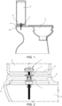
- the reference number 1 indicates a fastening device for fastening a flushing tank 2, in particular a flushing tank made of ceramic, plastic or other materials, to a sanitary bowl 3, in particular a sanitary bowl of a WC.
- a fitting kit comprising a pair of fastening devices 1, identical and positioned side by side, is normally used to fasten the flushing tank 2 to the sanitary bowl 3.
- the flushing tank 2 is fitted on a rear portion 4 of the sanitary bowl 3 and has a bottom wall 5 that rests on a wall 6 for supporting the portion 4 of the sanitary bowl 3.
- the bottom wall 5 of the flushing tank 2 and the wall 6 of the sanitary bowl 3 are provided with respective pairs of through holes 7 aligned with each other for housing respective fastening devices 1.
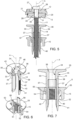
- each fastening device 1 extends along a longitudinal axis A and comprises a screw 11, a washer 12, a sealing ring 13, a fitting member 14 and a fixing nut 15.
- each fastening device 1 can comprise two (or even more) fitting members 14 of different lengths, interchangeable with one another, to be selected and used according to installation needs.
- the screw 11 has a stem 16 extending along the axis A and a head 17 positioned at an axial end of the stem 16 and provided with a slot 18 or other handling element that can be operated by means of a tool (for example a manual or electric screwdriver) to rotate the screw 11 around the axis A.
- the stem 16 comprises, starting from the head 17, a smooth upper portion 21, having a smooth outer lateral surface 22, and a lower threaded portion 23, provided with an external thread.
- the washer 12 is provided with a central through hole 26 that receives the stem 16, which is inserted sliding axially through the hole 26; the head 17 of the screw 11 abuts against an upper surface 27 of the washer 12; advantageously, the portion 21 is housed in the hole 26 and protrudes partially beyond the hole 26.
- a lower surface 28 of the washer 12 is provided with a seat 29 that houses the sealing ring 13.
- the sealing ring 13 for example made of EPDM or another elastomer, is fitted around the stem 16 and in particular the portion 21 that protrudes from the hole 26 of the washer 12; in particular, the sealing ring 13 has a central through hole 30 delimited by a radial sealing surface 31 that cooperates with fluid-tight seal with the lateral surface 22 of the portion 21.
- the sliding seats 43 comprise respective guides 44 formed on an outer lateral surface 45 of the body 33 and respective openings 46 formed passing through the flange 35 and aligned with the guides 44.
- the fixing nut 15 has an internally threaded central seat 51 formed passing through the fixing nut 15 along the axis A and shaped to screw onto the threaded portion 23 of the screw 11; a pair of coupling seats 52 formed passing along the axis A through the fixing nut 15 and arranged diametrically opposite with respect to the central seat 51; and a radially outer flange 53 substantially orthogonal to the axis A.
- the coupling seats 52 are shaped to receive respective arms 37 and are provided with respective clip arms 54, which project in a cantilevered manner in the coupling seats 52 and have respective teeth 55 facing each other and facing the axis A and shaped so as to engage respective toothed racks 40 of the arms 37 inserted into the coupling seats 52.
- the teeth 55 have an opposite profile with respect to the teeth 42.
- the arms 37 (having the toothed rack 40) and the coupling seats 52 (having the clip arms 54), and in particular their respective teeth 42, 55, are shaped so as to allow sliding of the arms 37 in the respective coupling seats 52 (and hence movement of the fitting member 14 with respect to the fixing nut 15) in a predetermined axial sliding direction (in which the flanges 35, 53 move closer each other) and prevent sliding in the opposite direction (in which the flanges 35, 53 move away from each other).
- fitting member 14 and the fixing nut 15 are joined by a quick coupling system 57, formed by the arms 37 provided with the toothed rack 40 and by the clip arms 54 of the coupling seat 52, cooperating with each other to connect the fitting member 14 and the fixing nut 15; the fitting member 14 and the fixing nut 15 are movable with respect to each other along the axis A in a predetermined axial sliding direction in which the flanges 35, 53 move closer to each other, and locked in the opposite direction.
- the arms 37 and/or the clip arms 54 being protruding elements with respective free ends, have a certain flexibility with respect to the axis A, which allows their relative sliding in the desired direction and not in the opposite direction.
- assembly of the fitting member 14 and of the fixing nut 15 on the sanitary bowl 3 is very easy and quick: the fitting member 14 and the fixing nut 15 are positioned respectively above and below the wall 6 and aligned on opposite sides of a hole 7, and are then pushed towards each other inserting the arms 37 of the fitting member 14 through the hole 7 and into the respective coupling seats 52 of the fixing nut 15, and the projections 58 of the fixing nut 15 into the respective sliding seats 43 of the fitting member 14.
- the arms 37 penetrate the respective coupling seats 52 until they are blocked in the desired position, when the flanges 35, 53 abut against respective opposite faces of the wall 6.
- the flushing tank 2 is then positioned above the wall 6 aligning the holes 7.
- the head 17 of the screw 11 can be easily rotated to tighten the screw 11 in the seat 51. Tightening of the screw 51 pushes the washer 12 and the sealing ring 13 against the bottom wall 5 of the flushing tank 2, until the bottom wall 5 is clamped between the washer 12 (provided with the sealing ring 13) and the flange 35 of the fitting member 14.
Landscapes
- Health & Medical Sciences (AREA)
- Life Sciences & Earth Sciences (AREA)
- Engineering & Computer Science (AREA)
- Hydrology & Water Resources (AREA)
- Public Health (AREA)
- Water Supply & Treatment (AREA)
- Sanitary Device For Flush Toilet (AREA)
Applications Claiming Priority (1)
| Application Number | Priority Date | Filing Date | Title |
|---|---|---|---|
| IT102023000014916A IT202300014916A1 (it) | 2023-07-17 | 2023-07-17 | Dispositivo di fissaggio per fissare una cassetta di risciacquo su un vaso sanitario |
Publications (1)
| Publication Number | Publication Date |
|---|---|
| EP4495344A1 true EP4495344A1 (de) | 2025-01-22 |
Family
ID=88413957
Family Applications (1)
| Application Number | Title | Priority Date | Filing Date |
|---|---|---|---|
| EP24187958.4A Pending EP4495344A1 (de) | 2023-07-17 | 2024-07-11 | Befestigungsvorrichtung zur befestigung eines spülkastens an einer sanitärwanne |
Country Status (2)
| Country | Link |
|---|---|
| EP (1) | EP4495344A1 (de) |
| IT (1) | IT202300014916A1 (de) |
Citations (5)
| Publication number | Priority date | Publication date | Assignee | Title |
|---|---|---|---|---|
| US4286497A (en) * | 1979-06-18 | 1981-09-01 | Shamah Alfred A | Ratchet-securable toggle retainer |
| EP2128351B1 (de) * | 2008-05-30 | 2013-11-06 | Toto Ltd. | Haltetank und Spültoilette damit |
| CN107476404A (zh) * | 2016-06-07 | 2017-12-15 | Toto株式会社 | 冲水大便器装置 |
| WO2019145123A1 (de) * | 2018-01-29 | 2019-08-01 | Fabian Nieberding | Unlösbare befestigungsvorrichtung |
| US20200124076A1 (en) * | 2019-12-18 | 2020-04-23 | 1552818 Ontario Limited | Ratchet toggle connector |
-
2023
- 2023-07-17 IT IT102023000014916A patent/IT202300014916A1/it unknown
-
2024
- 2024-07-11 EP EP24187958.4A patent/EP4495344A1/de active Pending
Patent Citations (5)
| Publication number | Priority date | Publication date | Assignee | Title |
|---|---|---|---|---|
| US4286497A (en) * | 1979-06-18 | 1981-09-01 | Shamah Alfred A | Ratchet-securable toggle retainer |
| EP2128351B1 (de) * | 2008-05-30 | 2013-11-06 | Toto Ltd. | Haltetank und Spültoilette damit |
| CN107476404A (zh) * | 2016-06-07 | 2017-12-15 | Toto株式会社 | 冲水大便器装置 |
| WO2019145123A1 (de) * | 2018-01-29 | 2019-08-01 | Fabian Nieberding | Unlösbare befestigungsvorrichtung |
| US20200124076A1 (en) * | 2019-12-18 | 2020-04-23 | 1552818 Ontario Limited | Ratchet toggle connector |
Also Published As
| Publication number | Publication date |
|---|---|
| IT202300014916A1 (it) | 2025-01-17 |
Similar Documents
| Publication | Publication Date | Title |
|---|---|---|
| US6484331B2 (en) | Waste and overflow system for a bathtub | |
| CN101904070B (zh) | 连接附件 | |
| US6367102B1 (en) | Drain assembly with installation aid stopper guide | |
| US9145665B2 (en) | Adjustable locking spout shank | |
| WO2002035130A2 (en) | Bayonet quick coupler | |
| CA2387583A1 (en) | Conduit system | |
| RU2549991C2 (ru) | Усовершенствованный узел установки крана | |
| US10422435B2 (en) | Diaphragm valve | |
| JP3689233B2 (ja) | 排水装置 | |
| CN108601491A (zh) | 马桶座的紧固系统、外壳、笼式螺母、应用、设备和方法 | |
| US7201404B1 (en) | Union nut with lock member | |
| US11015328B2 (en) | Sensor installation assembly, faucet and sensor installation method | |
| CA3154781A1 (en) | Connecting means for connecting a pipe to a pipe section at an opening, such as, for example, a pipe section at a discharge opening, and a method for connecting a pipe using such connecting means | |
| US7640603B2 (en) | Cistern outlet valve mounting bracket assembly and a method of installing an outlet valve in cistern | |
| IT202300014916A1 (it) | Dispositivo di fissaggio per fissare una cassetta di risciacquo su un vaso sanitario | |
| CN111433987B (zh) | 安装套筒 | |
| CN101802333A (zh) | 用于将配件固定在空心型材上的系统 | |
| WO2021009481A1 (en) | Apparatus and method for securing elongate objects | |
| JP5846492B2 (ja) | ユニットバスにおける混合水栓用継手の固定具 | |
| US6126205A (en) | Connection tool for low profile connections | |
| JP2000120118A (ja) | 配管装置 | |
| JP3011711B1 (ja) | 管継手及び配管方法 | |
| GB2637307A (en) | Pipe spacing system | |
| US20090015003A1 (en) | Sanitary Fitting Comprising A Connecting Device Which Is Used To Connect A Water Outlet Housing To A Functional Component | |
| JP2025519792A (ja) | トイレ装置 |
Legal Events
| Date | Code | Title | Description |
|---|---|---|---|
| PUAI | Public reference made under article 153(3) epc to a published international application that has entered the european phase |
Free format text: ORIGINAL CODE: 0009012 |
|
| STAA | Information on the status of an ep patent application or granted ep patent |
Free format text: STATUS: THE APPLICATION HAS BEEN PUBLISHED |
|
| AK | Designated contracting states |
Kind code of ref document: A1 Designated state(s): AL AT BE BG CH CY CZ DE DK EE ES FI FR GB GR HR HU IE IS IT LI LT LU LV MC ME MK MT NL NO PL PT RO RS SE SI SK SM TR |
|
| STAA | Information on the status of an ep patent application or granted ep patent |
Free format text: STATUS: REQUEST FOR EXAMINATION WAS MADE |
|
| 17P | Request for examination filed |
Effective date: 20250704 |